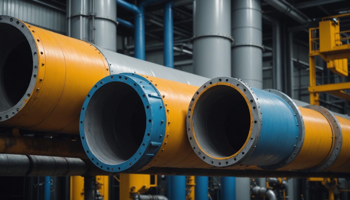
An insulated pipe loses heat through a stack of thermal resistances in series, and the detail that trips engineers up is geometry: heat spreading outward through a round pipe crosses an ever-larger area, so each layer's resistance follows the logarithm of its radius ratio, ln(r₂/r₁), not the flat-wall thickness over area.
Why Insulated Pipe Heat Loss Is Not a Flat-Wall Problem
The flat-wall formula (R = thickness / (k × area)) assumes constant area. In a pipe, the area grows with radius as heat moves out, so the correct cylindrical resistance is ln(r_outer/r_inner) / (2πkL). Using the flat-wall shortcut underestimates each layer's resistance, underestimates the total, and overstates the heat loss. The error grows with the outer-to-inner radius ratio, so it is worst for thick insulation on small pipe: exactly where insulation is specified. The composite-cylinder method uses the logarithmic form throughout.
The calculator models four resistances in series (inner fluid film, pipe wall, insulation, outer air film), sums them, and divides the temperature difference by the total to get heat flow per unit length. It works both directions: a hot pipe losing heat, with a surface-temperature check for personnel safety, and a cold pipe gaining heat, with a dew-point condensation check. ASTM C680 is the governing practice; ISO 12241 covers surface temperature and condensation. This article opens the heat-transfer sub-theme in the Plumbing cluster, pairing with the Heat Loss in Buried Pipes article: this one handles above-ground insulated pipe with an outer air film; that one replaces the air film with soil resistance below grade.
The physics is standard composite-cylinder conduction from any heat transfer textbook and codified in ASTM C680. The four resistances add in series because heat must cross each in turn; the largest resistance controls the result. For a well-insulated metal pipe, the insulation carries 85 to 97 percent of the total. Everything else is marginal: pipe material, inner film, air movement. Understanding the resistance hierarchy before sizing is what distinguishes an energy-efficient insulation design from one that wastes money on the wrong variable.
Calculator Inputs: Service Mode, Pipe, Insulation, Temperatures, Air Film
The calculator requires the following inputs. Each controls one resistance in the series chain.
Service Mode. Hot pipe (heat loss, fluid hotter than ambient, optional surface-temperature check against a personnel-protection target) or Cold pipe (heat gain, fluid cooler than ambient, optional condensation check against a computed dew point).
Unit System. SI (°C, mm, W/m·K, W/m²·K, W/m) or US (°F, in, Btu/h·ft·°F, Btu/h·ft²·°F, Btu/h·ft).
Fluid Temperature and Ambient Temperature. The temperature difference drives heat flow. Fluid temperature is inside the pipe; ambient is the surrounding air (or the humid ambient for condensation checks on cold lines).
Pipe Size Entry. Nominal (NPS Schedule 40, with ID/OD set automatically from ASME B36.10M) or Direct (enter inner and outer diameter explicitly). ASME B36.10M governs pipe dimensions: NPS ½ to 24 in, with actual OD independent of the nominal label.
Pipe Material. Carbon steel (k ≈ 45 W/m·K, 26 Btu/h·ft·°F), Stainless 316 (16 W/m·K, 9.3 Btu/h·ft·°F), Copper (400 W/m·K, 231), Plastic PEX/PVC (0.35 W/m·K, 0.20). The wall resistance is negligible for metal but matters for plastic.
Insulation Thickness. Radial thickness only. Zero means bare pipe. Insulation outer diameter equals pipe OD plus twice the radial thickness.
Insulation Material. Fiberglass or mineral wool (k ≈ 0.040 W/m·K, 0.023 Btu/h·ft·°F at 50°C mean), Foam PIR/PUR (0.026, 0.015 at 25°C), Cellular glass (0.050, 0.029 at 50°C), Calcium silicate (0.170, 0.098 at 150°C), Aerogel blanket (0.015, 0.009 at 25°C). Values from ASTM C518/C177/C335 test methods and manufacturer datasheets.
Outer Coefficient. Still air (h_o ≈ 9 W/m²·K, 1.6 Btu/h·ft²·°F), Moving air (25 W/m²·K, 4.4), or Custom for a combined convection plus radiation coefficient.
Inner Film and Optional Inputs. Liquid-full turbulent pipes: neglect the inner film (h_i ≫ 500 W/m²·K). Gas or viscous/laminar service: enter h_i explicitly. Optional pipe-run length gives total Q in addition to per-length. Optional surface-temperature target (hot) enables a degree-margin check; optional ambient relative humidity (cold) enables condensation verdict.
Calculator outputs: heat flow per unit length (primary), resistance breakdown percentages, boundary temperatures (fluid-wall interface, insulation outer surface), mean insulation temperature, overall U, total Q if length is entered, surface-target margin for hot service, and condensation margin for cold service.
Radial Conduction: The ln(r₂/r₁) Resistance of a Cylindrical Layer
The thermal resistance of a cylindrical layer is the natural log of its outer-to-inner radius ratio divided by 2πk, and this logarithmic form is the single most important departure from flat-wall heat transfer. Per composite-cylinder theory and ASTM C680:
R_cyl = ln(r₂ / r₁) / (2π × k)    [m·K/W per unit length]

  r₂ = outer radius of the layer [m]
  r₁ = inner radius of the layer [m]
  k  = thermal conductivity [W/m·K]  typical range: 0.015–0.50 W/m·K (insulation to metal)
  2π = uses RADIUS, not diameter
The flat-wall comparison makes the difference explicit:
Flat wall:  R = thickness / (k × A)     (A = constant cross-sectional area)
Cylinder:   R = ln(r₂/r₁) / (2π × k)   (area grows with radius r)
Why the logarithm: heat flowing outward crosses circumference 2πrL at radius r, and r increases continuously. Integrating 1/(2πrkL) from r₁ to r₂ yields ln(r₂/r₁)/(2πkL). The growing area reduces resistance compared to a naive flat-wall calculation at the inner radius. The flat-wall shortcut therefore underestimates each cylindrical layer's resistance, underestimates the total resistance, and overstates heat loss.
The error is proportional to the radius ratio: at r₂/r₁ = 1.1 (thin wall), the flat-wall error is roughly 5%. At r₂/r₁ = 2 (thick insulation on small pipe), it exceeds 30%. Thick insulation on small pipe is the most common insulation application, which is precisely where the flat-wall method fails most.
Worked calculation for NPS 4 with 50 mm (1.97 in) fiberglass insulation:
Pipe OD = 114.3 mm, r_po = 57.15 mm (2.25 in)
Insulation OD = 114.3 + 100 = 214.3 mm, r_ins = 107.15 mm (4.22 in)
k_ins = 0.040 W/m·K (0.023 Btu/h·ft·°F)

R_ins = ln(107.15/57.15) / (2π × 0.040)
      = ln(1.875) / 0.2513
      = 0.6286 / 0.2513
      = 2.500 m·K/W (1.449 h·ft·°F/Btu)
Using diameter instead of radius halves R_ins and doubles the computed heat loss, a frequent unit error. The formula uses radius throughout.
Resistances in Series: Inner Film, Pipe Wall, Insulation, Outer Film
Heat crosses four resistances in sequence from fluid to ambient air, so they add in series. Their sum sets the heat flow per unit length. Per ASTM C680:
R_total = R_conv_i + R_pipe + R_ins + R_conv_o

R_conv_i = 1 / (h_i × 2π × r_pi)          inner convective film [m·K/W]
R_pipe   = ln(r_po/r_pi) / (2π × k_pipe)   pipe wall conduction
R_ins    = ln(r_ins/r_po) / (2π × k_ins)   insulation conduction (0 if bare)
R_conv_o = 1 / (h_o × 2π × r_out)          outer convective film (r_out = r_ins if insulated)

q' = (T_fluid − T_amb) / R_total    [W/m]   positive = heat loss from hot pipe
The four layers behave as follows. The inner film (R_conv_i) represents convection from fluid to pipe wall; negligible for liquid-full turbulent service (h_i = 500 to 5,000 W/m²·K, 88 to 881 Btu/h·ft²·°F) but relevant for gas or viscous flow. The pipe wall (R_pipe) represents conduction through the metal or plastic; negligible for metal pipe (high k) but not for plastic (k ≈ 0.35 W/m·K). Insulation (R_ins) is the dominant resistance. The outer film (R_conv_o) represents convection from the insulation surface to ambient air; 5 to 15 percent of the total for typical conditions.
Like electrical resistors in series, thermal resistances add because heat must cross each in turn. The largest resistance controls the total; improving a small resistance changes almost nothing.
Steam line Example 4 illustrates the series addition (NPS 4, 180°C steam, 50 mm fiberglass, still air):
R_pipe   = 0.000392 m·K/W  (0.1% of total)
R_ins    = 2.500 m·K/W     (93.7%)
R_conv_o = 0.165 m·K/W     (6.2%)
R_total  = 2.665 m·K/W     (1.543 h·ft·°F/Btu)

q' = (180 − 25) / 2.665 = 58.2 W/m  (60.5 Btu/h·ft)
The Resistance Breakdown: Why Insulation Carries 85 to 97 Percent
The percentage each layer contributes to total resistance tells you where design effort matters. For a well-insulated metal pipe in still air, per ASTM C680:
Insulation:   85–97%  (dominant)
Outer film:   5–15%   (depends on air movement)
Pipe wall:    < 0.5%  (metal, negligible)
Inner film:   < 0.5%  (liquid-full, negligible)
The dominant-resistance rule has direct practical consequences. Switching pipe material from carbon steel (k = 45 W/m·K) to stainless steel (16 W/m·K) changes the pipe-wall resistance but leaves heat loss essentially unchanged, because the wall contributes under 0.1 percent. Pipe material selection can ignore heat loss entirely for an insulated metal pipe.
The outer film plays a dual role. It is small in the R_total percentage (6 to 10 percent), but it sets the surface temperature. Increasing wind speed from still air (h_o = 9 W/m²·K) to moving air (25 W/m²·K) reduces R_conv_o and lowers the surface temperature substantially, while barely changing total heat loss.
Where to focus design effort: if insulation dominates (the normal case), increasing insulation thickness or specifying lower-k material is the only lever that meaningfully reduces heat loss. If the outer film is large (thin or no insulation), the surface is exposed and air movement matters more.
The steam Example 4 breakdown: insulation 93.7%, outer film 6.2%, pipe wall 0.1%. Adding more insulation is the right design lever; changing pipe material or altering h_i is not.
Surface Temperature: What a Hand Touches and What Controls Condensation
The outer surface temperature is calculated by subtracting each layer's temperature drop from the fluid temperature. It governs two separate checks: personnel safety on hot pipes and condensation risk on cold pipes. Per ASTM C680:
T_pipe_surface  = T_fluid − q' × R_conv_i
T_interface     = T_pipe_surface − q' × R_pipe
T_outer_surface = T_interface − q' × R_ins
For a cold pipe, signs reverse: temperature rises outward (surface warmer than fluid, cooler than ambient).
Steam Example 4 shows how the drop distributes:
T_interface     = 180 − 58.2 × 0.000392 = 179.98°C (355.96°F)
T_outer_surface = 179.98 − 58.2 × 2.500 = 34.5°C  (94.1°F)
Of the 155°C total drop (180 to 25°C), 145.5°C drops across the insulation and only 9.0°C across the outer air film. The surface at 34.5°C is safe to touch: well below typical personnel-protection targets of 55 to 65°C.
Surface-temperature check (hot service):
margin = target − surface    [degrees, NOT a ratio]
margin ≥ 10°C:        MET
0 < margin < 10°C:    MET NEAR LIMIT
margin ≤ 0:           EXCEEDED
The check is a direct degree margin, not a percentage, because Celsius and Fahrenheit are not absolute scales. At a 60°C (140°F) personnel target and 34.5°C surface: margin = +25.5°C, MET. ASTM C1055 and C1057 address burn injury as a function of surface temperature and contact time; the calculator compares to the engineer-specified target, not a burn-injury standard directly.
For cold service, T_outer_surface is compared to the dew point computed from ambient temperature and humidity. Section 8 covers the condensation check in full.
Condensation on Cold Pipes: The Dew-Point Check
A cold pipe condenses moisture whenever its outer surface falls to or below the dew point of the surrounding air. Per ISO 12241 and the Magnus equation:
γ  = ln(RH/100) + 17.625 × T_amb / (243.04 + T_amb)
Td = 243.04 × γ / (17.625 − γ)    [°C]

condensation margin = T_surface − Td
margin ≤ 0 → CONDENSATION RISK
Example 3 shows the computation at ambient 25°C (77°F), RH 60%, outer surface 14°C (57.2°F):
γ  = ln(0.60) + 17.625 × 25 / (243.04 + 25)
   = −0.5108 + 1.6429
   = 1.1321

Td = 243.04 × 1.1321 / (17.625 − 1.1321)
   = 275.13 / 16.493
   = 16.7°C  (62.1°F)

margin = 14 − 16.7 = −2.7 K → CONDENSATION RISK
The surface at 14°C is below the 16.7°C dew point: moisture condenses. The fix is to add insulation thickness, which raises the outer surface temperature by reducing how much cold reaches it. On cold lines, insulation thickness is often sized by the condensation check, not by heat gain.
Condensation matters because dripping water damages equipment and structure below the pipe, and persistent moisture drives corrosion under insulation (CUI). The surface must remain above the dew point under design ambient conditions throughout the service life. This requires conservative ambient humidity assumptions: design for the most humid months, not average annual conditions.
Insulation Conductivity Rises with Temperature
Insulation conductivity is not a fixed number; most materials conduct more heat when hotter, so the correct k depends on the mean temperature inside the insulation, not room temperature. Per ASTM C518, C177, and C335:
Mean insulation temperature = (T_inner_surface + T_outer_surface) / 2
k must be taken at this mean temperature
Typical k values at stated mean temperature:
Fiberglass/mineral wool:   0.040 W/m·K (0.023 Btu/h·ft·°F) at ~50°C (122°F) mean
Foam PIR/PUR:              0.026 W/m·K (0.015) at ~25°C (77°F) mean
Cellular glass:            0.050 W/m·K (0.029) at ~50°C mean
Calcium silicate:          0.170 W/m·K (0.098) at ~150°C (302°F) mean
Aerogel blanket:           0.015 W/m·K (0.009) at ~25°C mean
Room-temperature k from a catalog understates heat loss on a hot steam pipe, because the actual mean insulation temperature is much higher and k rises accordingly. For a steam line at 180°C, fiberglass k at the ~90°C mean is higher than the 50°C catalog value. The calculator reports the mean insulation temperature for this reason: cross-check k against the manufacturer's datasheet at that mean temperature before accepting the result.
The k(T) effect is largest for calcium silicate (used on high-temperature steam) and mineral wool (general industrial). Aerogel and rigid foam are relatively flat over their operating ranges. Verify k at actual mean temp; using room-temperature k is the most common heat-loss underestimate on hot piping.
The Critical Radius and Why Ordinary Pipe Is Past It
There is a critical insulation outer radius below which adding insulation actually increases heat loss. Per heat-transfer theory:
r_crit = k_ins / h_o    [m]

  k_ins = insulation conductivity [W/m·K]
  h_o   = outer heat transfer coefficient [W/m²·K]
Below r_crit, adding insulation enlarges the outer surface area faster than it adds resistance, so total heat loss rises. Above r_crit, resistance wins and loss falls normally.
Worked:
Fiberglass, k = 0.040 W/m·K, still air, h_o = 9 W/m²·K:
r_crit = 0.040 / 9 = 0.00444 m = 4.44 mm (0.175 in)
The smallest common pipe, NPS ½ in, has OD = 21.3 mm and r_po = 10.65 mm, which already exceeds r_crit = 4.44 mm. Every standard pipe size is past the critical radius for fiberglass in still air. Adding insulation always reduces heat loss on normal industrial or building pipe.
Where the critical radius matters: small tubes (< 10 mm diameter), electrical wire insulation, and thin capillaries where the pipe radius is at or below r_crit. A bare small tube with thin insulation can lose more heat than the bare tube alone. This has no practical relevance for building or industrial pipe insulation but appears in heat transfer coursework precisely because it is counterintuitive.
Steam Line Worked Example: NPS 4 at 180 Degrees to a 35-Degree Surface
This example matches calculator Example 4: steam distribution line, NPS 4 carbon steel, 50 mm (1.97 in) fiberglass insulation, 180°C (356°F) steam, 25°C (77°F) ambient, still air.
Step 1. Set radii from ASME B36.10M (Schedule 40):
ID = 102.3 mm → r_pi = 51.15 mm (2.014 in, 0.05115 m)
OD = 114.3 mm → r_po = 57.15 mm (2.250 in, 0.05715 m)
Insulation OD = 114.3 + 100 = 214.3 mm → r_ins = 107.15 mm (4.219 in, 0.10715 m)
Step 2. Pipe wall resistance (carbon steel, k = 45 W/m·K):
R_pipe = ln(57.15/51.15) / (2π × 45)
       = ln(1.1173) / 282.74
       = 0.1109 / 282.74
       = 0.000392 m·K/W
Step 3. Insulation resistance (fiberglass, k = 0.040 W/m·K):
R_ins = ln(107.15/57.15) / (2π × 0.040)
      = ln(1.875) / 0.2513
      = 0.6286 / 0.2513
      = 2.500 m·K/W  (1.449 h·ft·°F/Btu)
Step 4. Outer film resistance (still air, h_o = 9 W/m²·K, 1.584 Btu/h·ft²·°F):
R_conv_o = 1 / (9 × 2π × 0.10715)
         = 1 / 6.060
         = 0.165 m·K/W
Step 5. Total resistance and breakdown:
R_total = 0.000392 + 2.500 + 0.165 = 2.665 m·K/W

Insulation: 2.500/2.665 = 93.7%
Outer film: 0.165/2.665 =  6.2%
Pipe wall:  0.000392/2.665 = 0.1%
Step 6. Heat loss per unit length:
q' = (180 − 25) / 2.665 = 58.2 W/m (60.5 Btu/h·ft)
Step 7. Surface temperatures:
T_interface     = 180 − 58.2 × 0.000392 = 179.98°C (355.96°F)
T_outer_surface = 179.98 − 58.2 × 2.500 = 34.5°C (94.1°F)
Surface 34.5°C: personnel target 60°C, margin +25.5°C, MET.
Step 8. Total for a 100 m (328 ft) run:
Q = 58.2 × 100 = 5,820 W = 5.82 kW (19,860 Btu/h)
At 8,760 h/yr: ~51,000 kWh/yr of steam heat lost to ambient.
Step 9. Effect of moving air (h_o = 25 W/m²·K, 4.4 Btu/h·ft²·°F):
R_conv_o = 1 / (25 × 2π × 0.10715) = 0.059 m·K/W
R_total  = 0.000392 + 2.500 + 0.059 = 2.559 m·K/W
q'       = 155 / 2.559 = 60.6 W/m  (63.0 Btu/h·ft)

T_outer_surface = 25 + 60.6 × 0.059 = 28.6°C (83.5°F)
Moving air raises heat loss by only 4% (58.2 to 60.6 W/m) but drops the surface temperature by 5.9°C (34.5 to 28.6°C). The outer film resistance is small in R_total, so wind barely changes heat loss; but it is large relative to the temperature drop near the surface, so it changes surface temperature significantly.
Decision: 50 mm fiberglass on NPS 4 at 180°C gives 58.2 W/m (60.5 Btu/h·ft), surface 34.5°C, personnel target met. Cross-reference: this steam line's condensate returns and flashes (see Condensate Return Line Sizing); thermal growth of the line requires expansion loops (see Pipe Expansion Loop Sizing).
Cold Line and Condensation Worked Examples
Two scenarios matched to calculator outputs: a chilled-water heat-gain check and a condensation verdict.
Cold line heat gain (HL-1, Example 1). Chilled line: inner diameter 81 mm (3.19 in), wall 2.3 mm, OD 85.6 mm. Insulation 25 mm (0.98 in) foam PIR (r_ins = 67.8 mm, 2.67 in, k = 0.035 W/m·K). Fluid 4°C (39.2°F), ambient 15°C (59°F), pipe k = 30 W/m·K, 3.5 m (11.5 ft) run, convection neglected.
Step 1. Radii:
r_pi = 40.5 mm, r_po = 42.8 mm, r_ins = 67.8 mm
Step 2. Resistances:
R_pipe = ln(42.8/40.5) / (2π × 30)
       = ln(1.0568) / 188.5
       = 0.0553 / 188.5
       = 0.000293 m·K/W

R_ins  = ln(67.8/42.8) / (2π × 0.035)
       = ln(1.584) / 0.2199
       = 0.4601 / 0.2199
       = 2.092 m·K/W

R_total = 2.092 m·K/W  (insulation 99.9%)
Step 3. Heat gain:
q' = (4 − 15) / 2.092 = −5.26 W/m (−5.47 Btu/h·ft)

Q  = −5.26 × 3.5 = −18.4 W (−62.8 Btu/h)
Negative sign: cold pipe gains heat from the warmer ambient. The 18.4 W gain over 3.5 m is the thermal load added to the chilled-water system. The metal wall resistance is four orders of magnitude smaller than the insulation and contributes nothing.
Condensation check (Example 3). Separate chilled line, outer surface at 14°C (57.2°F), ambient 25°C (77°F), RH 60%.
Step 4. Dew point (Magnus equation):
γ  = ln(0.60) + 17.625 × 25 / (243.04 + 25) = −0.5108 + 1.6429 = 1.1321
Td = 243.04 × 1.1321 / (17.625 − 1.1321) = 275.13 / 16.493 = 16.7°C (62.1°F)
Step 5. Condensation verdict:
margin = 14 − 16.7 = −2.7 K → CONDENSATION RISK
Surface 14°C is below the 16.7°C dew point: moisture condenses on the insulation surface. Adding insulation thickness raises the outer surface toward ambient, lifting it above the 16.7°C threshold. On this line, condensation governs insulation sizing, not the 18.4 W heat gain.
Cold-line insulation design differs from hot-line design: on a hot pipe, you minimize heat loss to reduce energy cost; on a cold pipe, you minimize heat gain to reduce refrigeration load and, critically, ensure the surface stays above the dew point to prevent condensation damage. Cross-reference: for pipes below grade where soil replaces the air film, see Heat Loss in Buried Pipes.
Application Boundaries: Fittings, Multi-Layer, Wet Insulation, Buried Pipe
The calculator handles steady-state heat transfer in a single-layer insulated straight pipe run above grade. Per ASTM C680 and ISO 12241, the following conditions fall outside this scope.
Fittings, valves, flanges, and supports. The model covers straight pipe only. Bare valve bodies, flanges, and pipe supports are thermal bridges that add loss beyond the straight pipe. Add allowances (equivalent straight-pipe length or per-item losses) when a run contains many fittings or bare components.
Multi-layer insulation. The model accepts one insulation layer. Multi-layer systems (for example, cellular glass inner layer plus mineral wool outer) require each layer summed separately in the resistance network, using the correct inner and outer radii for each.
Radiation from surface emissivity. Outer-surface radiation is excluded unless you enter a combined convection plus radiation h_o. For hot surfaces, radiation is a real part of heat transfer; use the manufacturer-recommended combined h_o or calculate it separately using the Stefan-Boltzmann law and surface emissivity.
Wet insulation and CUI. The model assumes dry insulation. Wet insulation (from rain, condensation, or vapor-barrier failure) has conductivity 10 to 100 times higher than dry and drives corrosion under insulation. Vapor-barrier performance is not modeled.
Buried pipe. Above-ground only (outer boundary is air film). Buried pipe replaces the air film with soil conduction resistance and a different outer boundary condition. Cross-reference the Heat Loss in Buried Pipes Calculator.
Transient, warm-up, and variable fluid temperature. Steady-state only. Long runs where fluid cools appreciably should be segmented and computed per segment.
Insulation sizing (inverse problem). The calculator computes heat loss and surface temperature for a given thickness. Sizing thickness to meet a target heat loss, surface temperature, or condensation margin is a separate inverse calculation.
A qualified engineer and current manufacturer datasheet data should be used for final design.
Insulated Pipe Heat Loss Calculator
Open Insulated Pipe Heat Loss Calculator
Composite-cylinder method per ASTM C680: inner film, pipe wall, insulation, and outer air film as resistances in series. Reports heat flow per unit length, resistance breakdown, boundary temperatures, and mean insulation temperature. Hot mode checks surface against a personnel-protection target; cold mode checks surface against the dew point. SI and US units, steam and chilled service.
Open CalculatorFAQ
Why does insulated pipe heat loss use a logarithm, not thickness over area?
Per composite-cylinder theory and ASTM C680: heat spreading outward through a cylindrical layer crosses an ever-larger circumferential area, so resistance follows ln(r₂/r₁)/(2πk) rather than the flat-wall thickness/area. The flat-wall shortcut underestimates resistance and overstates heat loss. The error is worst for thick insulation on small pipe, where the radius ratio r₂/r₁ is largest.
Does doubling insulation thickness halve the heat loss?
Per the logarithmic resistance relationship: no. Resistance grows as ln(r₂/r₁), not linearly with thickness. Each added layer of insulation contributes less than the previous one; the third 25 mm layer reduces heat loss far less than the first. This diminishing return is why insulation thickness is an economic optimum, not a maximize-it decision. ASTM C680 uses this logarithmic form for all cylindrical-layer calculations.
How do I check for condensation on a chilled line?
Per ISO 12241 and the Magnus equation: compute the outer surface temperature from the composite-cylinder model, then compare to the dew point derived from ambient temperature and relative humidity. At 25°C and 60% RH, the dew point is 16.7°C. If the surface temperature is at or below the dew point, condensation occurs. Add insulation thickness to raise the surface above it.
Why does insulation conductivity change with temperature?
Per ASTM C518, C177, and C335: most thermal insulation conducts more when hotter, because radiation within fibers and pores increases with temperature. Room-temperature k from a catalog understates heat loss on a steam pipe where the actual mean insulation temperature is 80 to 150°C. Use the manufacturer's k(T) curve at the calculated mean insulation temperature.
What is the critical radius of insulation?
Per heat-transfer theory: the critical radius is k_ins/h_o, typically 4 to 6 mm for mineral wool in still air. Below this radius, adding insulation raises heat loss because the enlarged outer surface area increases convective loss faster than the added conduction resistance reduces it. All standard pipe sizes (NPS ½ in OD = 21.3 mm) are well past this radius, so on normal pipe, more insulation always reduces heat loss.
Does pipe material affect heat loss on an insulated pipe?
Per ASTM C680: barely. The metal pipe wall carries under 0.5% of the total resistance when properly insulated; insulation carries 85 to 97 percent. Switching from carbon steel (k = 45 W/m·K) to stainless steel 316 (k = 16 W/m·K) changes the pipe-wall resistance by a factor of three but moves total heat loss by less than 0.5%.
Is straight-pipe heat loss the complete system loss?
Per ASTM C680: no. Fittings, valves, flanges, hangers, and bare supports are thermal bridges that add loss beyond the straight-pipe model. On runs with many components, especially bare valve bodies and bare flanges, add per-item allowances or equivalent-length factors. The straight-pipe model is a lower bound on system heat loss, not the total.
Related Calculators
- Heat Loss in Buried Pipes Calculator: The below-grade counterpart, replacing the outer air film with soil conduction resistance for buried and direct-buried pipe.
- Condensate Return Line Sizing Calculator: Flash-steam condensate sizing for the steam lines whose heat loss this calculates (article).
- Pipe Expansion Loop Sizing Calculator: Guided-cantilever thermal loops for the hot steam piping being insulated (article).
- Water Heater Sizing Calculator: First-hour rating per DOE 10 CFR 430 for the hot-water systems whose distribution loses heat (article).
- Expansion Tank Sizing Calculator: Thermal expansion control per IPC Section 607.3 (article).
- Hazen-Williams Pipe Flow Calculator: Pressurized water pipe flow per AWWA M22 (article).
- Hanger Load Calculator: Support load per MSS SP-58 for insulated pipe (add insulation weight) (article).