Pipe Expansion Loop Sizing Calculator | Guided Cantilever
On this page
Calculate
e.g. 100 ft, the restrained segment whose movement feeds this loop
e.g. 70 °F, the temperature at which the pipe was anchored (strain-free state)
e.g. 350 °F, highest expected service temperature
e.g. −20 °F, enter only if cooling below installation temperature
e.g. 20000 psi, from ASME B31.3 Table A-1 at the cold / minimum temperature
e.g. 18500 psi, from ASME B31.3 Table A-1 at the hot / maximum temperature
e.g. 1.0 for ≤ 7,000 cycles, from ASME B31.3 Table 302.3.5; blank defaults to 1.0
e.g. 18 ft, enter the leg length available in your pipeway to get a stress ratio and verdict
e.g. 6.33 (US) or 11.39 (Metric), overrides material default; blank uses material profile
e.g. 28.5 Mpsi (US) or 196.5 GPa (Metric), use E at design temperature; blank uses material profile reference value
e.g. 5 ft, overrides default 3 ft (US) / 1 m (Metric) practical access and fabrication floor
Overview
A long pipe run grows as it heats up. A 100 foot carbon steel line going from 70 to 350 degrees Fahrenheit stretches roughly 2 inches, and that movement has to go somewhere. If the run is locked between two anchors with nowhere to flex, the force lands on the anchors and the elbows until something yields or cracks. A U-shaped expansion loop gives the pipe a place to bend, absorbing the growth in the loop legs instead of in the anchors.
This calculator sizes that loop. You enter the run length, the temperature change, the pipe size, and the material, and it returns the flexible leg length the loop needs, the loop width and height, and the straight developed length of pipe to add. The run length is the restrained length between anchors whose growth is assigned to this loop, not the whole system. It uses the guided-cantilever method, the classic hand-calc behind expansion loop sizing, and it works in both US and metric units.
One thing to be clear about: the guided-cantilever method is a preliminary screen, and it runs on the conservative side. A full flexibility analysis in software like CAESAR II or AutoPIPE often allows a smaller loop, because it credits elbow flexibility and the real boundary conditions. Treat this tool as a sound first number, not a substitute for a stamped stress analysis.
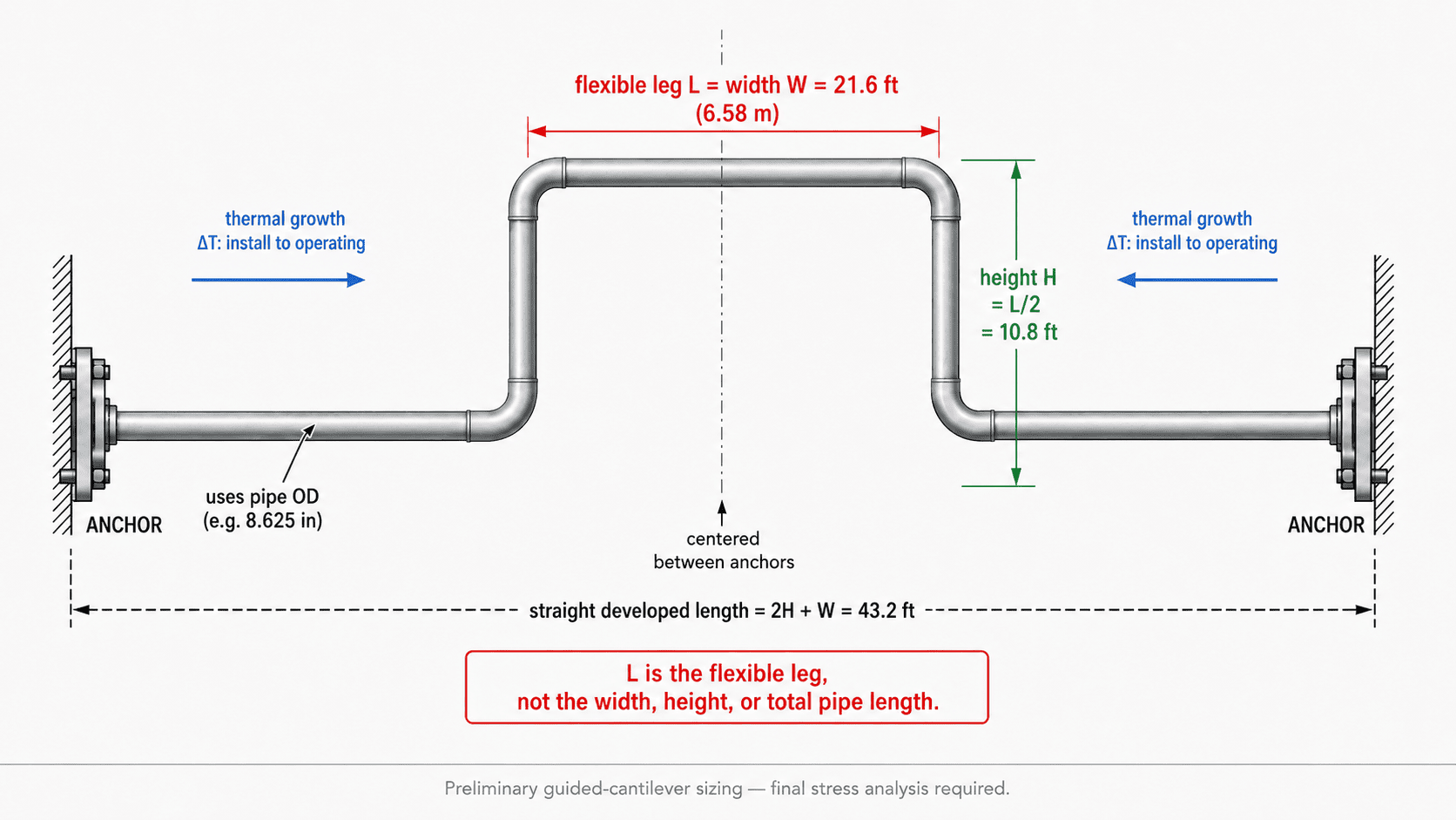
A U-loop centered between anchors absorbs thermal growth in its flexible legs; the guided-cantilever method sizes leg length L from movement, pipe OD, modulus, and allowable stress.
What to Look at First
- Recommended leg: the flexible leg length the U-loop needs to absorb the thermal growth within the allowable stress range
- Straight developed length: total layout length of pipe to add for the loop (width + 2 × height); does not include elbow arcs or routing allowances
- Stress ratio (candidate mode): ratio of required leg² to candidate leg²; ≤ 1.00 is ADEQUATE, > 1.00 is UNDERSIZED with the shortfall shown
How to Use
Choose the unit system (US or Metric) and the pipe material. The material sets the default expansion coefficient and modulus.
Select the nominal pipe size. The calculator looks up the outside diameter; loop stiffness depends on OD, not on the nominal label.
Enter the run length between anchors. Use the restrained segment whose movement feeds this loop, not the full system.
Enter the installation temperature and operating temperature range. Growth is measured from the installation temperature.
Choose the code basis and enter the allowable stress parameters (Sc, Sh, f for B31.3, or Sa directly for B31.1 or Manual).
Read the required flexible leg length, loop dimensions, and straight developed length.
Optional: enter a candidate leg length to get a stress ratio and pass/fail verdict.
For systems with multiple anchors or complex routing, this tool covers one restrained segment at a time. Apply the guided-cantilever method to each segment separately, or use formal software such as CAESAR II or AutoPIPE for a network analysis.
Inputs & Outputs
Inputs
System Definition
Stress Basis
Outputs
Sizing Results
Formula
Thermal movement (governing case)
ΔT_gov = max( |T_max − T_install| , |T_min − T_install| )
ΔL     = α × ΔT_gov × L_run            [in]   α is mean coefficient over the range
growth rate = ΔL ÷ L_run               report per 100 ft
ΔT is measured from the installation temperature, the temperature at which the pipe was anchored and is free of thermal strain.
Guided-cantilever flexible leg (US unit basis)
L = sqrt( 3 × E × D × ΔL / (144 × Sa) )      L in ft
  E   = modulus at design temperature, psi
  D   = pipe OUTSIDE diameter, in (nominal size only looks up OD)
  ΔL  = full thermal movement assigned to the loop, in (do not halve)
  Sa  = allowable stress range, psi
  144 = in² → ft² unit constant (mandatory; dropping it errs by ×12)
Verified benchmark: E 28.5×10⁶ psi, D 8.625 in, ΔL 2.73 in, Sa 30,000 psi → L = sqrt(3 × 28.5×10⁶ × 8.625 × 2.73 / (144 × 30,000)) = sqrt(466.0) = 21.6 ft (6.58 m)
Allowable stress range
B31.3:  Sa = f × (1.25 × Sc + 0.25 × Sh)
  Sc = basic allowable at cold/min temperature
  Sh = basic allowable at hot/max temperature
  f  = stress-range reduction factor (cycle count)
B31.1:  use B31.1 allowable basis; enter Sa directly
Manual: enter project-specific Sa directly
U-loop geometry
loop width  W = L
loop height H = L / 2
straight developed length = 2H + W
Candidate check (stress ratio)
stress_ratio = (L_stress_required / L_candidate)²
shortfall    = L_stress_required − L_candidate
  ratio ≤ 0.90           ADEQUATE
  0.90 < ratio ≤ 1.00   ADEQUATE AT LIMIT
  1.00 < ratio ≤ 1.15   UNDERSIZED (MARGINAL)
  1.15 < ratio ≤ 1.50   UNDERSIZED
  ratio > 1.50           SIGNIFICANTLY UNDERSIZED
What the Leg Length, Developed Length, and Stress Ratio Mean
Leg length and loop dimensions. The guided-cantilever method returns one number: L, the flexible leg. That is the straight length of pipe perpendicular to the run that bends to absorb the thermal growth. It is not the loop width, not the height, and not the total pipe you order. In the standard U-loop layout, the width equals L and the height equals L/2, so the straight developed length (the layout length of pipe added to the system) is 2H + W = 2L. For a 22 foot leg that means about 44 feet of pipe in the loop, before elbow arcs and routing allowances.
Stress ratio in candidate mode. When you enter a candidate leg length, the calculator returns a stress ratio equal to (L_required / L_candidate)². A ratio at or below 1.00 means the candidate can absorb the movement within the allowable stress range. A ratio above 1.00 means the candidate leg is too short, and the shortfall tells you how much more you need. The ratio squares the leg comparison because bending stress in a cantilever scales with the square of the deflection-to-length ratio.
Practical minimum and the advisory flag. The guided-cantilever formula can return a very short leg on short, cool runs. A 2.5 foot loop is structurally sound on paper but difficult to build, access, and insulate. The practical minimum floor defaults to 3 feet (1 meter in metric) and raises the recommendation when the stress result falls below it. This triggers the BELOW-MIN-PRACTICAL advisory, which is informational (the stress criterion is still satisfied); the recommended size is governed by construction practicality.
Key Facts
- Carbon steel grows about 0.75 inch per 100 feet for every 100 degrees Fahrenheit of temperature rise.
- The guided-cantilever leg formula is L = sqrt(3 × E × D × ΔL / (144 × Sa)), with L in feet, and it uses the pipe outside diameter.
- The method is intentionally conservative and commonly sizes loops 15 to 30 percent longer than a full flexibility analysis in CAESAR II or AutoPIPE.
- Thermal growth is measured from the installation temperature, not ambient, because that is the strain-free starting point.
- Plastic pipe moves far more than steel. CPVC expands roughly four to five times as much as carbon steel for the same temperature change.
- The loop belongs at the midpoint between anchors so each leg shares the movement equally. Off-center loops load the anchors unevenly.
- A fully restrained carbon steel pipe with no loop develops about 188 psi of thermal stress per degree Fahrenheit, before relaxation, shakedown, and boundary effects.
- The straight developed length is 2H + W = 2L in the standard U-loop layout. It is the layout length only and does not include elbow arc lengths or routing allowances.
Applications
- Steam and hot water distribution mains in plants and campuses
- Process piping runs subject to temperature swings between shutdown and operation
- Chilled water and refrigerant lines, where contraction can govern instead of expansion
- Long straight runs between fixed anchors that exceed roughly 150 to 200 feet
- Rack and pipeway routing where a loop must fit a known available width
- A preliminary routing estimate before a formal pipe stress analysis
- Checking whether an existing loop still has enough leg for a revised operating temperature
Example Calculation
Example 1: Required loop leg (LEG-1 benchmark)
Given: NPS 8 carbon steel (OD 8.625 in), thermal movement 2.73 in, modulus 28.5 million psi at temperature, allowable stress range 30,000 psi.
L = sqrt( 3 × 28,500,000 × 8.625 × 2.73 / (144 × 30,000) )
  = sqrt( 2,013,199,875 / 4,320,000 )
  = sqrt( 466.0 )
  = 21.6 ft  (6.58 m)
U-loop layout:
  width  W = 21.6 ft
  height H = 10.8 ft
  straight developed = 2 × 10.8 + 21.6 = 43.2 ft
Result: the loop needs a 21.6 ft flexible leg, and about 43.2 ft of straight pipe in layout, before elbow arcs.
Example 2: Candidate check
Given: same NPS 8 run (required leg 21.6 ft), pipeway only has room for an 18 ft leg.
stress_ratio = (21.6 / 18)² = 1.44   → UNDERSIZED
shortfall    = 21.6 − 18   = 3.6 ft
Result: the 18 ft leg falls short. Bending stress runs 44 percent over the allowable. Add at least 3.6 ft, reroute to a wider bay, or engage a formal flexibility analysis.
Example 3: Contraction governs
Given: stainless line installed at 80 °F, operating between +120 °F and −20 °F.
Heating case:  |120 − 80| = 40 °F
Cooling case:  |−20 − 80| = 100 °F  ← governs
ΔT_gov = 100 °F  (contraction case)
Result: cooling moves the pipe more than heating. On chilled and cryogenic systems, always check both directions.
Example 4: B31.3 Sa calculation
Given: Sc = 20,000 psi, Sh = 18,000 psi, f = 1.0.
Sa = 1.0 × (1.25 × 20,000 + 0.25 × 18,000)
   = 25,000 + 4,500
   = 29,500 psi
Standards & References
- ASME B31.3, Process Piping:Governs flexibility, displacement stress range, thermal expansion coefficients, and allowable stresses for process piping
- ASME B31.1, Power Piping:Governs thermal expansion, flexibility, and allowable stresses for power piping including steam and hot-water distribution
- ASME B31.3 Appendix C: Coefficients of thermal expansion and moduli of elasticity (part of the B31.3 code linked above)
- Copper Development Association, copper tube technical references:Thermal expansion data for copper tube used in this calculator
- M.W. Kellogg and Tube Turns guided-cantilever references: Classical basis of the guided-cantilever method, cited by name as the historical foundation of the approach
Limitations
- Preliminary guided-cantilever screen only, commonly 15 to 30 percent conservative versus a full 3D flexibility analysis that credits elbow flexibility and real boundary conditions
- Sizes one U-loop on one restrained run; multi-anchor networks require a formal flexibility model
- Does not compute anchor forces, guide spacing, or support loads from the added loop weight
- Does not perform an ASME B31 stress-range analysis or apply stress intensification factors at elbows
- Does not check equipment nozzle loads, buried-pipe soil friction, branch connections, intermediate anchors, or real boundary stiffness
- Does not model thermal bowing, cold spring, pressure thrust, weight, wind, or seismic loads
- Reflects cycle count only through the f factor, no detailed fatigue life computation
- Assumes constant mean α over the temperature range; use code expansion tables above roughly 600 °F
- Straight developed length excludes elbow arc lengths, weld takeoff, spool allowances, and routing constraints
- Plastic pipe, expansion joints, Z-bends, L-bends, lyre loops, and anchor force outputs are deferred to future versions
- Final design must be confirmed by formal stress analysis and a qualified engineer under the governing code
Common Mistakes to Avoid
- Measuring temperature change from ambient instead of the installation temperature: the pipe is strain-free at the temperature where it was anchored
- Reading L as the loop width or the total pipe to order: L is the flexible leg; the developed length is a separate, larger number
- Using the whole system length instead of the restrained run: use the segment between anchors whose movement feeds this loop
- Halving ΔL in the formula: the leg formula uses the full movement assigned to the loop, not half of it
- Using the nominal pipe size in the formula: loop stiffness depends on the actual outside diameter from the schedule
- Dropping the 144 constant: without it the answer is off by a factor of 12
- Using a room-temperature modulus for hot service: E should match the design temperature or the code table value
- Counting the straight developed length as the pipe purchase length: it is the layout length; elbows, takeoff, and routing allowances are separate
Frequently Asked Questions
What does the L in the expansion loop formula represent?
Why does the formula use outside diameter instead of nominal size?
Should I measure temperature change from ambient or from installation?
Can I use the overall system length for the run?
Does the developed length include the elbows?
Does contraction matter, or only expansion?
Can a full stress analysis allow a smaller loop?
What is the stress-range reduction factor f?
Frequently Used Together
Engineers often use these calculators in combination for complete project workflows:
Related Calculators
Explore similar calculators that might be useful for your project:
Plumbing Quick Reference — Keep It On Your Phone On Site
A 10-page field reference for catching pressure, velocity, slope, and pump-sizing mistakes before you order pipe, close a wall, or add a booster.
- Velocity limits, fixture pressure minimums, drain slope, and the 80 psi ceiling in one table
- Worked examples that show why a single pressure number gives four different answers
- Keep it on your phone, or print the two field-check pages
Free PDF. Calculators stay free. Unsubscribe anytime.
Calculate
e.g. 100 ft, the restrained segment whose movement feeds this loop
e.g. 70 °F, the temperature at which the pipe was anchored (strain-free state)
e.g. 350 °F, highest expected service temperature
e.g. −20 °F, enter only if cooling below installation temperature
e.g. 20000 psi, from ASME B31.3 Table A-1 at the cold / minimum temperature
e.g. 18500 psi, from ASME B31.3 Table A-1 at the hot / maximum temperature
e.g. 1.0 for ≤ 7,000 cycles, from ASME B31.3 Table 302.3.5; blank defaults to 1.0
e.g. 18 ft, enter the leg length available in your pipeway to get a stress ratio and verdict
e.g. 6.33 (US) or 11.39 (Metric), overrides material default; blank uses material profile
e.g. 28.5 Mpsi (US) or 196.5 GPa (Metric), use E at design temperature; blank uses material profile reference value
e.g. 5 ft, overrides default 3 ft (US) / 1 m (Metric) practical access and fabrication floor