Buried Pipe Heat Loss Calculator — Soil & Insulation
On this page
Calculate
Outer-surface temperature of the pipe. For bare metal pipes this is approximately the fluid temperature. For precise work use the pipe outer-surface temperature.
Ground-surface or design boundary temperature from your project basis. Seasonal variation is not computed — use the design condition for your climate and season.
Outside diameter from ASME B36.10M. This is the bare pipe OD; for an insulated pipe the soil resistance uses the insulation outer diameter (D_boundary).
Depth value measured according to the basis selected below.
The shape factor needs depth to the pipe centre. Cover-to-crown is converted automatically: z = cover + pipe radius (basis 2) or z = cover + insulation radius (basis 3).
Soil conductivity depends heavily on moisture. Wet soil can carry several times the heat of dry soil. Select the condition for your site and season, or use the site override below.
Site-specific value from geotechnical data. If entered, this overrides the profile selection. A soft check will fire to confirm the basis.
Length of the pipe run. If entered, total heat loss Q is computed in addition to the per-unit-length result.
For steel and copper the pipe wall resistance is negligible. Include it for plastic (PVC, HDPE) or thick-wall pipe. Requires pipe ID and pipe wall conductivity below.
Design heat loss limit per unit length from your project specification. If entered, the calculator checks computed loss against this allowable and returns a pass/fail verdict.
Overview
This calculator finds the steady-state heat loss — or heat gain, for a chilled line — from a single horizontal pipe buried in soil, bare or insulated. From the pipe temperature, the ground temperature, the burial depth, the pipe size, any insulation, and the soil's thermal conductivity, it returns the heat loss per unit length and for the whole run, the thermal resistances and their shares, and which resistance governs. It serves district heating, hot- and chilled-water mains, process and steam lines, and freeze-protection planning.
The model is steady conduction from the pipe to the ground surface, a temperature difference divided by a chain of thermal resistances. What sets a buried pipe apart from one in air is the soil path: heat spreads from the pipe out through the ground to the surface, and that resistance is found from a conduction shape factor for a horizontal cylinder in a semi-infinite medium, which depends on how deep the pipe sits relative to its size. An above-ground insulation formula does not capture it.
Two things shape the tool. First, the surface the soil sees is the outside of whatever is in the ground: the pipe wall for a bare pipe, but the outside of the insulation for an insulated pipe. Using the bare pipe's diameter for the soil path of an insulated line is a real and common error, and it is handled correctly here. Second, soil conductivity depends heavily on moisture — saturated soil can carry several times the heat of dry soil — so it is the single biggest source of uncertainty, shown with its basis rather than hidden in a constant. The result names the governing resistance, soil or insulation, so the design lever is clear.
What to Look at First
Heat loss per unit length. The first result is the steady-state heat loss (or gain, for a chilled line) per metre or per foot of pipe run. This is the primary output that drives insulation selection and energy accounting.
Governing resistance. The breakdown shows whether soil or insulation governs. For a bare pipe the soil is the only barrier; once insulation is added it usually governs. Knowing which controls tells you where to focus design effort.
Soil moisture basis. The soil conductivity used is shown with its moisture label. Because wet soil can carry several times the heat of dry soil, this input often dominates the result more than any other single parameter. Verify it matches your site and season.
Bare pipe baseline (insulated pipe only). When a pipe is insulated, the tool also computes the bare-pipe heat loss and the percentage reduction from the insulation. If the reduction is modest, consider increasing insulation thickness.
Track B verdict (when allowable entered). If you entered an allowable heat loss, the ratio and verdict (Within limit / At limit / Exceeds limit) appear. Use this to check whether the insulation design meets the project specification.
How to Use This Calculator
Choose whether the pipe is bare or insulated. Insulation fields appear only for an insulated pipe.
Enter the pipe or fluid temperature and the ground boundary temperature. The difference drives the heat loss. The temperature is treated as the pipe outer-surface temperature for the conduction model.
Enter the pipe size as a nominal size (ASME B36.10M) or a direct outside diameter.
Enter the burial depth and choose what it is measured to: the pipe centre, the cover over the pipe crown, or the cover over the insulation crown.
Choose the soil type and moisture condition to set the soil conductivity. You can enter a site-specific override if you have geotechnical data.
For an insulated pipe, choose the insulation material and enter the insulation thickness. Optionally enter a jacket outside diameter if the pre-insulated pipe system uses one.
Read the result: heat loss or gain per unit length, the resistance breakdown with each share of the total, and the governing resistance. Enter a pipe length to get the total, or an allowable heat loss for a pass/fail check.
This is a steady-state estimate for one isolated horizontal pipe. It does not model adjacent pipes, groundwater flow, seasonal swings, or the temperature drop of fluid along a long run. For chilled lines it gives the heat gain but does not evaluate condensation or vapour barriers.
Inputs & Outputs
Inputs
Outputs
Formula
Buried Pipe Heat Loss Formula
The heat loss per unit length is the temperature difference divided by the total thermal resistance:
q = (T_pipe − T_ground) / R_total W per metre
The resistances are in series. The soil resistance comes from the conduction shape factor for a horizontal cylinder in a semi-infinite medium:
R_soil = acosh(2z / D_boundary) / (2π × k_soil)       general form
R_soil ≈ ln(4z / D_boundary) / (2π × k_soil)          when z > 1.5 × D_boundary
Where z is the depth to the pipe centre and D_boundary is the diameter of the surface in contact with the soil. D_boundary is the pipe OD for a bare pipe, but the insulation OD for an insulated pipe — the soil sees the insulation surface, not the pipe.
The insulation resistance is the standard annular form (zero for a bare pipe):
R_ins = ln(D_ins_OD / D_pipe_OD) / (2π × k_ins)
For a thick or plastic pipe wall (optional):
R_pipe = ln(D_pipe_OD / D_pipe_ID) / (2π × k_pipe)
Total resistance and total heat loss over a run of length L:
R_total = R_soil + R_ins + R_pipe
Q       = q × L
The equivalent shape-factor form Q = S × k_soil × ΔT with S = 2πL / acosh(2z / D_boundary) agrees with the resistance form and provides a cross-check.
What is Buried Pipe Heat Loss
A pipe buried in soil loses heat to the ground around it whenever the fluid is warmer than the earth, and gains heat when it is colder, as with a chilled-water line. Unlike a pipe in open air, where heat leaves through the insulation and then to the air by convection, a buried pipe loses heat by conduction spreading outward through the soil to the ground surface.
The heat flow is set by the temperature difference between the pipe and the ground and by the resistances in the path. For a bare pipe, the only meaningful resistance is the soil itself. The soil resistance is not a simple wall formula; it comes from a conduction shape factor for a cylinder buried in a semi-infinite medium, which depends on the ratio of the burial depth to the radius of the buried surface. A pipe buried deep has more soil around it and a higher soil resistance than the same pipe buried shallow.
Why the Insulation Diameter Matters
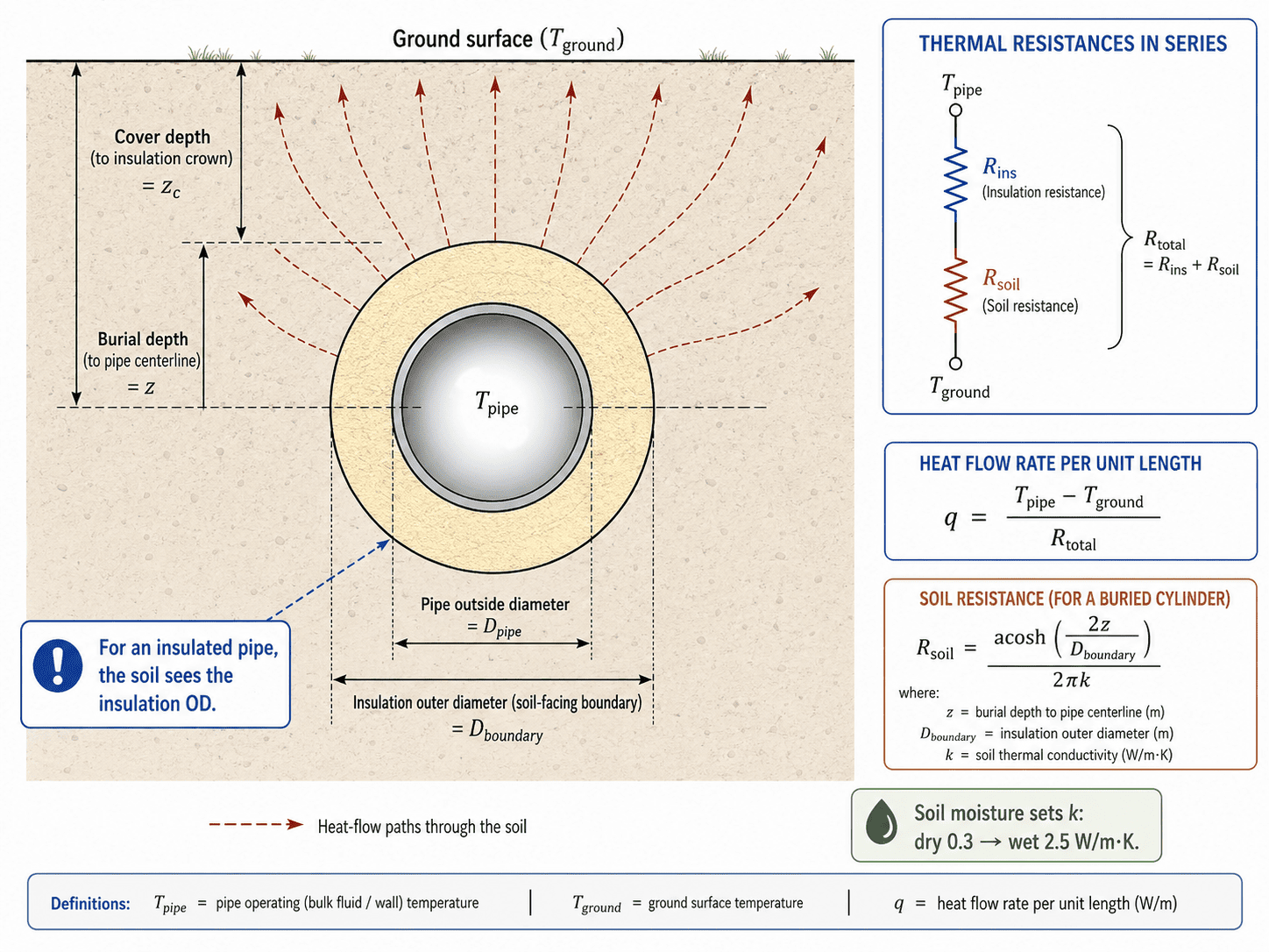
For an insulated buried pipe, the insulation adds a resistance in series with the soil. The detail that must be right is which diameter the soil sees. For a bare pipe, the soil is in contact with the pipe wall, so the pipe's outside diameter sets the soil resistance. For an insulated pipe, the soil is in contact with the outside of the insulation, so the insulation's outside diameter sets it. Standard heat-transfer texts are explicit: for an insulated buried pipe, the diameter used in the soil shape factor is the diameter of the exterior surface of the insulation, not the pipe. Using the bare pipe's diameter for an insulated line understates the soil-facing surface and gets the soil resistance wrong. This is the single most common buried-pipe heat-loss error.
Soil Resistance and the Shape Factor
The soil resistance is what makes a buried pipe different from a pipe in air, and it is not a flat-wall calculation. Heat leaves the buried surface and spreads outward through the ground in curved paths to the surface, and that spreading is captured by a conduction shape factor for a horizontal cylinder in a semi-infinite medium.
The shape factor depends on the ratio of the burial depth to the radius of the buried surface, through an inverse hyperbolic cosine. A pipe buried deeper has more soil around it and a higher soil resistance; a shallow pipe has less. For a pipe buried deep enough — roughly when the depth exceeds about one and a half times the buried diameter — the inverse-hyperbolic-cosine simplifies to a logarithm, which is the form most often seen in textbooks. For shallow burial the simplification breaks down and the full inverse-hyperbolic-cosine form is needed, and the result is more sensitive to depth.
Why Soil Moisture Matters
Soil thermal conductivity is the input that most often decides a buried-pipe result, and it varies more than most people expect. Dry sandy soil can be around 0.3 watts per metre-kelvin, ordinary moist soil near 1.0, and wet or saturated soil above 2.5 — a range of nearly ten to one between dry and saturated. Moisture is the main driver of that range. Water conducts heat far better than the air it displaces in the soil pores, so wetting the ground sharply raises its conductivity. For a bare pipe, where the soil is the only resistance, the heat loss scales almost directly with the soil conductivity, so the moisture condition can change the answer by a factor of several.
Buried Pipe Heat Loss vs Freeze Protection
Buried-pipe heat loss and freeze protection are related but not the same calculation. This tool gives the steady-state rate of heat loss — how fast the pipe sheds heat to the ground at a fixed set of temperatures. Freeze protection asks a different question: will the water in the pipe reach freezing, and if so, when. That is a transient problem. Whether a pipe freezes depends on the heat loss, but also on the fluid's heat capacity, whether it is flowing or stagnant, the inlet temperature, and the time available. A pipe with a high steady-state heat loss may never freeze if water keeps flowing through it, and a pipe with a modest loss may freeze if it sits stagnant long enough. The heat loss from this calculator is a useful input to a freeze-protection analysis — it sizes the heat that trace heating or flow must replace — but it is not a freeze prediction on its own.
Key Facts
- Soil thermal conductivity varies from roughly 0.3 W/m·K for dry soil to above 2.5 W/m·K for saturated soil — a range of nearly ten to one. Moisture is the dominant variable.
- For a bare pipe, the soil resistance governs entirely (100% of R_total). Heat loss scales almost directly with the soil conductivity, so wet ground can mean several times the heat loss of dry ground.
- For an insulated buried pipe, the soil sees the insulation's outer surface, not the pipe wall. Using the bare-pipe diameter for the soil path of an insulated line is the most common buried-pipe heat-loss error.
- Once a reasonable insulation thickness is added, the insulation usually governs — often 80–95% of R_total — with the soil adding the remainder. The soil is always in series and never disappears.
- The shape factor uses the depth to the pipe centre. If a drawing gives cover to the top of the pipe or to the insulation crown, the centre depth must be computed by adding the appropriate radius.
- For shallow burial (depth less than about 1.5 times the buried diameter), the full inverse-hyperbolic-cosine form of the shape factor must be used — the logarithmic simplification loses accuracy there.
- A steady-state heat loss does not predict whether a pipe will freeze. Freeze protection requires a transient analysis accounting for the fluid's heat capacity, flow rate, and time.
- For a chilled line (T_pipe < T_ground), the result is a heat gain. The physics and formulas are identical; only the direction changes. Condensation control and vapour barriers are separate checks.
Applications
- Estimating heat loss from a buried district-heating or hot-water main to size insulation or quantify energy loss.
- Estimating heat gain into a buried chilled-water line to plan insulation thickness and assess condensation risk.
- Comparing bare versus insulated configurations and quantifying the reduction in heat loss from a given insulation thickness.
- Checking whether the soil or the insulation is the governing resistance before adjusting insulation thickness.
- Assessing the sensitivity of heat loss to soil moisture — running dry versus wet soil scenarios to bracket the design range.
- Providing the per-metre heat loss as an input to freeze-protection sizing, pipe temperature-drop calculations, or a larger energy balance.
- Screening heat loss from a buried process or steam line where the soil path dominates (bare or lightly insulated pipe).
- Evaluating the effect of burial depth on heat loss for district heating or chilled-water system design.
Example Calculation
Example 1 — Bare pipe, soil resistance only (Metric)
A bare pipe of 100 mm outside diameter (4 in, NPS 4) is buried with its centre 0.5 m deep, in moist soil with a conductivity of 0.9 W/m·K, over a 30 m run. Pipe surface temperature is 80°C, ground temperature 10°C.
D_boundary = pipe OD = 0.1 m
z = 0.5 m (to pipe centre)

Depth ratio: 0.5 / 0.1 = 5.0  →  deep, use ln form
R_soil = ln(4 × 0.5 / 0.1) / (2π × 0.9) = ln(20) / 5.655 = 2.996 / 5.655 = 0.530 m·K/W
R_total = 0.530 m·K/W
q = (80 − 10) / 0.530 = 132 W/m
Q = 132 × 30 = 3,960 W
The pipe loses about 132 W/m and 3,960 W over the 30 m run. Soil is the only resistance.
Example 2 — Add insulation; the soil diameter changes (Metric)
The same pipe receives 50 mm of polyurethane foam insulation (k = 0.025 W/m·K).
Insulation OD = 0.1 + 2 × 0.05 = 0.2 m    ← D_boundary for the soil
R_ins  = ln(0.2 / 0.1) / (2π × 0.025) = 0.693 / 0.157 = 4.415 m·K/W
R_soil = ln(4 × 0.5 / 0.2) / (2π × 0.9) = ln(10) / 5.655 = 2.303 / 5.655 = 0.407 m·K/W
R_total = 4.415 + 0.407 = 4.822 m·K/W
q = 70 / 4.822 = 14.5 W/m  →  Q = 14.5 × 30 = 435 W
Insulation cuts the heat loss from 132 W/m to 14.5 W/m — a 89% reduction. Insulation governs at 92% of R_total; soil adds 8%. Note the soil now uses D_boundary = 0.2 m (the insulation surface), not 0.1 m.
Example 3 — Dry vs wet soil, bare pipe (Metric)
The bare pipe of Example 1 in dry soil (k = 0.3 W/m·K) versus saturated soil (k = 2.5 W/m·K).
Dry:  q = 70 / (ln(20) / (2π × 0.3)) = 70 / 1.587 = 44 W/m
Wet:  q = 70 / (ln(20) / (2π × 2.5)) = 70 / 0.191 = 367 W/m
The wet soil loses more than eight times the heat of the dry — the ratio of the conductivities — because the soil is the only resistance.
Example 4 — Chilled pipe, heat gain (Metric)
The insulated pipe of Example 2, carrying chilled water at 5°C with the ground at 25°C.
ΔT = 5 − 25 = −20°C  →  heat gain (ground is warmer)
q = 20 / 4.822 = 4.1 W/m heat gain
Physics and resistances are identical; only the direction reverses. Condensation and vapour barriers are separate checks.
Example 5 — Depth measured to insulation crown (Metric)
An insulated pipe has a 200 mm insulation OD and 450 mm of cover over the top of the insulation.
z = cover + insulation radius = 0.45 + 0.10 = 0.55 m to pipe centre
Using the 0.45 m cover directly, or adding the pipe radius instead of the insulation radius, would put the centre at the wrong depth and produce an incorrect soil resistance.
Standards & References
- Bergman, Lavine, Incropera & DeWitt — Fundamentals of Heat and Mass Transfer (Wiley) — conduction shape factor for a horizontal isothermal cylinder buried in a semi-infinite medium; the rule that an insulated buried pipe uses the insulation's exterior diameter
- Carslaw & Jaeger — Conduction of Heat in Solids (Oxford University Press) — foundational treatment of conduction shape factors, including the buried-cylinder geometry
- ASHRAE Handbook — Fundamentals — soil and insulation thermal conductivity, buried-pipe thermal analysis guidance; manufacturer data for pre-insulated pipe giving certified insulation conductivity and jacket dimensions
- ASME B36.10M — Welded and Seamless Wrought Steel Pipe — pipe outside diameters and schedule dimensions used for the nominal-size lookup table
Limitations
- This is a steady-state estimate for a single isolated horizontal pipe in uniform soil. It is a screening and preliminary-design aid, not a substitute for a detailed thermal model or the project's design basis.
- It assumes a uniform pipe temperature along the run. For a long line, the fluid cools or warms along its length, and the run should be divided into segments or solved with an energy balance.
- It models one pipe. It does not account for adjacent buried pipes or the thermal interference between supply and return lines in a shared trench.
- It does not model groundwater flow, soil freezing and thawing, seasonal swings in ground temperature, or transient startup.
- It does not include pavement, snow cover, surface insulation, or layered soil unless these are represented through an adjusted boundary temperature or conductivity. It treats the soil as a uniform semi-infinite medium.
- It does not model a pipe in a duct, conduit, casing, or utility tunnel, where an air space changes the resistance, and it does not include contact resistance between pipe, insulation, and soil.
- It does not predict whether a pipe will freeze. Freeze protection requires a transient analysis, not a steady-state heat loss.
- The internal film and pipe-wall temperature drop are not modelled by default; the entered temperature is treated as the pipe outer-surface temperature.
Common Mistakes to Avoid
- Using the pipe outside diameter for the soil path of an insulated pipe. The soil is in contact with the insulation's exterior, so the insulation's outside diameter sets the soil resistance — standard heat-transfer texts are explicit on this.
- Treating the soil path as a flat wall or using an above-ground convection formula. The soil resistance comes from a conduction shape factor for a buried cylinder, not a thickness-over-area wall formula.
- Ignoring soil moisture. Soil conductivity can vary by a factor of eight or more between dry and saturated conditions, making it the single largest source of uncertainty in a buried-pipe heat-loss calculation.
- Confusing the depth basis. The shape factor uses the depth to the pipe centre. Entering cover to the pipe crown or cover to the insulation crown without converting to centre depth places the pipe at the wrong depth and throws off the soil resistance.
- Using air temperature as the ground boundary temperature. The design ground temperature at depth can differ substantially from the air temperature, particularly in winter and summer extremes.
- Assuming more insulation gives proportional improvement. The insulation and soil resistances are in series, so once the insulation dominates, adding more thickness gives diminishing returns — the soil always remains in the circuit.
- Treating a uniform-temperature result as valid over a very long run. The fluid cools or warms along its length. For long lines, divide the run into segments or use an energy balance.
- Treating a low steady-state heat loss as proof against freezing. Freeze protection is a transient problem that depends on flow, heat capacity, and time — a steady-state loss is one input, not the answer.
Frequently Asked Questions
How do you calculate heat loss from a buried pipe?
Why does the soil resistance use the insulation diameter, not the pipe diameter?
How much does soil moisture affect buried pipe heat loss?
Does burial depth reduce heat loss from a buried pipe?
Does insulation always govern buried pipe heat loss?
What soil conductivity should I use?
Does this calculator predict whether a buried pipe will freeze?
Can I use this for two pipes in the same trench?
Frequently Used Together
Engineers often use these calculators in combination for complete project workflows:
Related Calculators
Explore similar calculators that might be useful for your project:
Plumbing Quick Reference — Keep It On Your Phone On Site
A 10-page field reference for catching pressure, velocity, slope, and pump-sizing mistakes before you order pipe, close a wall, or add a booster.
- Velocity limits, fixture pressure minimums, drain slope, and the 80 psi ceiling in one table
- Worked examples that show why a single pressure number gives four different answers
- Keep it on your phone, or print the two field-check pages
Free PDF. Calculators stay free. Unsubscribe anytime.
Calculate
Outer-surface temperature of the pipe. For bare metal pipes this is approximately the fluid temperature. For precise work use the pipe outer-surface temperature.
Ground-surface or design boundary temperature from your project basis. Seasonal variation is not computed — use the design condition for your climate and season.
Outside diameter from ASME B36.10M. This is the bare pipe OD; for an insulated pipe the soil resistance uses the insulation outer diameter (D_boundary).
Depth value measured according to the basis selected below.
The shape factor needs depth to the pipe centre. Cover-to-crown is converted automatically: z = cover + pipe radius (basis 2) or z = cover + insulation radius (basis 3).
Soil conductivity depends heavily on moisture. Wet soil can carry several times the heat of dry soil. Select the condition for your site and season, or use the site override below.
Site-specific value from geotechnical data. If entered, this overrides the profile selection. A soft check will fire to confirm the basis.
Length of the pipe run. If entered, total heat loss Q is computed in addition to the per-unit-length result.
For steel and copper the pipe wall resistance is negligible. Include it for plastic (PVC, HDPE) or thick-wall pipe. Requires pipe ID and pipe wall conductivity below.
Design heat loss limit per unit length from your project specification. If entered, the calculator checks computed loss against this allowable and returns a pass/fail verdict.