Pipe Heat Loss Calculator (Insulated): Composite Cylinder
On this page
Calculate
Hot mode computes heat loss and optionally checks a surface-temperature target. Cold mode computes heat gain and optionally checks condensation risk.
Operating temperature of the fluid inside the pipe.
Temperature of the surrounding air or environment. For cold pipes this is the humid ambient; for hot pipes this is the air the insulation surface faces.
Nominal size sets actual Schedule 40 inner and outer diameters from ASME B36.10M. Use direct entry for non-standard pipe or exact geometry.
Outside diameter from ASME B36.10M. Inside diameter from Schedule 40. The actual radii, not the nominal label, are used in all calculations.
Sets the pipe wall conductivity. For metal pipes the wall resistance is usually negligible; for plastic pipe it can be comparable to the insulation resistance.
Radial insulation thickness. Enter 0 to model a bare (uninsulated) pipe. Insulation OD = pipe OD + 2 × thickness.
Sets insulation conductivity at the stated mean insulation temperature. If your mean insulation temperature differs significantly, use a k value from the manufacturer datasheet at the actual mean temperature.
The outer heat transfer coefficient h_o. The custom option accepts a combined convection-plus-radiation value, which is appropriate for high-temperature surfaces where radiation is significant.
For liquid-filled pipes with turbulent flow (h_i ≈ 500–5000 W/m²·K) the inner film resistance is typically negligible. It can matter for gases, viscous fluids, low flow, or laminar flow.
Straight-pipe run length. If entered, total heat loss Q is computed in addition to the per-unit-length result. For long runs, segment the pipe to account for temperature drop along the line.
Maximum allowable outer surface temperature. The calculator compares the computed surface temperature to this target and returns a margin. Margin = target − surface; no temperature ratio is used.
Overview
An insulated pipe still loses heat. The question is how much, and whether the outer surface ends up hot enough to touch safely or cold enough to drip. This calculator answers both. It models the pipe as a stack of thermal resistances in series: the fluid film inside, the pipe wall, the insulation, and the air film outside. Heat flows from the hot fluid to the cooler air across that stack, and the size of each resistance decides how much gets through and what temperature each surface reaches.
The key detail that trips people up is geometry. Heat spreading outward through a round pipe does not follow the flat-wall formula. As heat moves out, it crosses an ever-larger area, so the resistance follows a logarithm of the radius ratio, ln(r₂/r₁), not a simple thickness divided by area. Skip that and you underestimate the loss, badly for thick insulation. The calculator uses the cylindrical form throughout, works in SI and US units, and handles both hot pipes losing heat and cold pipes gaining it, with a condensation check for the cold case and a surface-temperature check for the hot case.
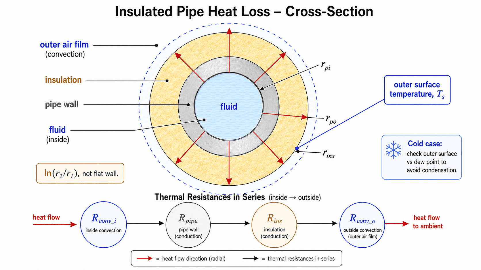
An insulated pipe modeled as thermal resistances in series (inner film, pipe wall, insulation, outer air film), with radial heat flow following ln(r₂/r₁) rather than the flat-wall formula.
What to Look at First
Heat loss per unit length. The first result is the heat loss or heat gain per metre (or per foot) of pipe run. This is the primary output for insulation selection and energy accounting. A negative sign internally means heat gain (cold pipe); the display always shows the magnitude with a direction word.
Resistance breakdown. The percentages show which layer carries the most resistance. For a well-insulated pipe, the insulation typically carries 85–97% of R_total. If the outer film dominates, adding insulation will help more than changing the pipe material.
Boundary temperatures. Check the outer surface temperature against your design limit or personnel-protection target for hot pipes. For cold pipes, compare it to the dew point: if the surface is at or below the dew point, condensation is expected.
Track B verdict. On a hot pipe, enter a surface-temperature target to get a pass or fail check. On a cold pipe, enter the ambient relative humidity or dew point to get a condensation verdict with the margin. The heat-flow result always appears regardless of whether a Track B reference is entered.
How to Use This Calculator
Choose service mode: a hot pipe losing heat, or a cold pipe gaining heat. The cold case adds a condensation check.
Choose the unit system, then enter the fluid temperature and ambient temperature.
Select the pipe size and material. The nominal size sets the actual inner and outer radii from Schedule 40. Choose Direct entry to enter explicit inner and outer diameters.
Enter the insulation thickness and select the insulation material. Leave thickness at zero to model a bare pipe.
Set the outer coefficient: choose a still-air or moving-air preset, or enter a custom value. The custom value can represent a combined convection-plus-radiation coefficient.
Choose whether to include the inner film resistance. For liquid-full pipes at normal velocities the inner film is usually negligible.
Click Calculate. Read the heat flow per unit length, the resistance breakdown, and all boundary temperatures.
Optional: enter pipe length to get the total heat flow. For a hot pipe, enter a surface-temperature target to get a surface check. For a cold pipe, enter ambient relative humidity or dew point to get a condensation verdict.
This is a steady-state calculation for one straight pipe run with one insulation layer. It does not model fittings, valves, flanges, supports, multi-layer insulation, radiation-from-emissivity iteration, buried pipe, or fluid temperature drop along a long run.
Inputs & Outputs
Inputs
Outputs
Formula
Insulated Pipe Heat Loss Formula
Heat flow per unit length is the temperature difference divided by the total thermal resistance, with each layer in series.
q' = (T_fluid − T_amb) / R_total            [W/m]   signed: positive = loss
R_total = R_conv_i + R_pipe + R_ins + R_conv_o

R_conv_i = 1 / (h_i · 2π · r_pi)            inner film (0 if neglected)
R_pipe   = ln(r_po / r_pi) / (2π · k_pipe)  pipe wall
R_ins    = ln(r_ins / r_po) / (2π · k_ins)  insulation (0 if bare pipe)
R_conv_o = 1 / (h_o · 2π · r_out)           outer film (r_out = r_ins if insulated)
U_o      = 1 / (R_total · 2π · r_out)       overall coefficient

Q_total  = q' × L    direction: loss if q'>0, gain if q'<0
The 2π·r terms use a radius. Using a diameter there halves the resistance and doubles the heat flow.
Boundary temperatures:
T_pipe_surface  = T_fluid − q' × R_conv_i
T_interface     = T_pipe_surface − q' × R_pipe
T_outer_surface = T_interface   − q' × R_ins
Magnus dew point (cold mode):
γ  = ln(RH/100) + 17.625·T_amb / (243.04 + T_amb)
Td = 243.04·γ / (17.625 − γ)    [°C]
Surface target check (hot mode):
margin = target_temp − surface_temp
margin ≥ 10°C → SURFACE TARGET MET
0 < margin < 10°C → SURFACE TARGET MET, NEAR LIMIT
margin ≤ 0 → SURFACE TARGET EXCEEDED
Insulated Pipe Heat Loss Formula
An insulated pipe loses heat because the fluid inside is at a different temperature from the air outside. Heat travels outward through four resistances in series: the convective film at the inner pipe wall, the pipe wall itself, the insulation layer, and the convective film at the outer insulation surface. Summing these resistances gives a total thermal resistance, and dividing the temperature difference by the total resistance gives the heat flow per unit length.
The geometry of a round pipe matters. As heat moves outward it crosses a growing area, so the resistance of each cylindrical layer follows a logarithm of the radius ratio, ln(r_outer/r_inner), not the flat-wall formula of thickness divided by area. Using the flat-wall approximation for a round pipe underestimates the resistance of each layer, underestimates the total resistance, and therefore overstates the heat loss. The error grows with the ratio of outer to inner radius, which means it is largest for thick insulation on small pipes.
Composite-Cylinder Resistance in Series
The four resistances add in series because heat must cross all four layers in sequence from the fluid to the air. The largest resistance controls the result, so knowing the percentage share of each layer tells you where to focus design effort. For a well-insulated pipe in still air, the insulation typically carries 85 to 97 percent of the total resistance. The pipe wall of a metal pipe is usually negligible. The outer air film can carry 5 to 15 percent depending on air movement. The inner film is usually negligible for liquid-filled pipes at normal velocities.
This hierarchy has a practical implication: on a well-insulated pipe, changing the pipe material from carbon steel to stainless steel has no meaningful effect on heat loss, because the wall resistance is already tiny. Thickening the insulation has diminishing returns. Increasing air movement past the surface raises heat loss slightly but lowers the outer surface temperature significantly, because the outer film drops from the total resistance.
Surface Temperature and What It Controls
The outer surface temperature is computed by subtracting the temperature drops across each inner layer from the fluid temperature, using the signed heat flow. On a hot pipe the temperature falls monotonically outward; on a cold pipe it rises. The outer surface temperature is what a hand touches, what determines personnel safety, and what controls whether moisture condenses on a cold pipe.
For hot pipes, a surface-temperature target check is available. The comparison is direct: target minus computed surface equals the margin, with no temperature ratio. Celsius and Fahrenheit are not absolute scales, so a percentage of a temperature is meaningless. The margin is in degrees.
For cold pipes, the condensation check compares the outer surface temperature to the dew point of the surrounding air. If the surface is at or below the dew point, moisture will condense on the surface, drip, and over time contribute to corrosion under insulation. The dew point is computed from the ambient temperature and relative humidity using the Magnus equation, or entered directly. The condensation margin is in degrees: surface temperature minus dew point.
Why Insulation Conductivity Changes With Temperature
Insulation conductivity is not a fixed number. For most materials k rises with temperature, sometimes steeply for calcium silicate and mineral wool at elevated temperatures. The correct k depends on the mean temperature inside the insulation, which is the average of the inner and outer insulation surface temperatures. This calculator shows the mean insulation temperature as an output, which you can compare to the temperature listed on the manufacturer datasheet to verify whether the assumed k is appropriate. A value taken at room temperature from a catalog understates the loss on a high-temperature steam pipe.
Key Facts
- Radial conduction through a pipe follows ln(r₂/r₁), not thickness over area. The flat-wall shortcut underestimates heat loss, especially for thick insulation.
- On a typical insulated steel pipe, the insulation provides 85–97% of the total resistance. The steel wall and the inner water film are usually negligible.
- Doubling insulation thickness does not halve the heat loss, because the resistance grows with the logarithm of the radius ratio, not linearly.
- The outer air film matters. A still-air coefficient near 9 W/m²·K gives a much higher surface temperature than a wind-exposed 25 W/m²·K value.
- The critical radius r_crit = k_ins / h_o is only a few millimetres for normal pipe insulation, so ordinary pipes are already well past it. It matters mainly for small tubes and electrical wires.
- A cold pipe condenses moisture whenever its outer surface falls to or below the dew point. At 25°C and 60% relative humidity the dew point is about 16.7°C.
- Insulation conductivity climbs with temperature, so a value measured at room temperature understates heat loss on a hot line. Use manufacturer k(T) data at the actual mean insulation temperature.
- The result is for one straight pipe run. Total system heat loss is higher once fittings, valves, flanges, and supports (which are thermal bridges) are included.
Applications
- Steam, condensate, and hot-water distribution where heat loss is an energy cost.
- Chilled water, refrigerant, and process-cooling lines that risk surface condensation.
- Checking insulation thickness against a heat-loss or surface-temperature goal.
- Personnel-protection reviews on hot piping in plant rooms and walkways.
- Comparing insulation materials by their effect on heat loss and surface temperature.
- Providing the heat-loss rate used as an input to an annual energy or emissions estimate.
- Pre-insulation engineering checks before specifying insulation class and thickness.
- Cold-pipe systems: verifying that the outer surface stays above the dew point under design conditions.
Example Calculation
Example 1: Cold line, heat gain (HL-1 benchmark)
Given: pipe inner diameter 81 mm, wall 2.3 mm (outer 85.6 mm), insulation 25 mm (outer 135.6 mm), pipe k 30 W/m·K, insulation k 0.035 W/m·K, fluid 4°C, ambient 15°C, length 3.5 m. Conduction only: inner film and outer film both neglected to match the benchmark source.
r_pi = 40.5 mm   r_po = 42.8 mm   r_ins = 67.8 mm
R_pipe = ln(42.8/40.5) / (2π × 30)     = 0.000293 m·K/W
R_ins  = ln(67.8/42.8) / (2π × 0.035)  = 2.090   m·K/W
R_total ≈ 2.090 m·K/W
q'  = (4 − 15) / 2.090 = −5.26 W/m   → heat gain
Q   = −5.26 × 3.5 = −18.4 W   → Heat gain 18.4 W
Result: the cold line gains about 18.4 W over 3.5 m. The insulation supplies essentially all the resistance; the steel wall is four orders of magnitude smaller.
Example 2: Surface temperature target, hot pipe
Given: computed outer surface temperature 55°C, surface target 60°C.
margin = 60 − 55 = +5°C → SURFACE TARGET MET, NEAR LIMIT
Result: the surface sits 5°C below the target. If the computed surface were 65°C, the margin would be −5°C and the target would be exceeded.
Example 3: Condensation check, cold pipe
Given: ambient 25°C at 60% relative humidity, computed outer surface 14°C.
γ  = ln(0.60) + 17.625 × 25 / (243.04 + 25) = −0.5108 + 1.6429 = 1.1321
Td = 243.04 × 1.1321 / (17.625 − 1.1321) = 274.19 / 16.49 ≈ 16.7°C
margin = 14 − 16.7 = −2.7 K   → CONDENSATION RISK
Result: the surface is below the dew point, so moisture will condense. Add insulation thickness to raise the surface above 16.7°C.
Example 4: Steam line, full resistance breakdown
Given: NPS 4 steel pipe (OD 114.3 mm, ID 102.3 mm), 50 mm fiberglass insulation (k 0.040 W/m·K), steam at 180°C, ambient 25°C, still-air h_o = 9 W/m²·K, inner film neglected, pipe k 45 W/m·K.
r_pi = 51.15 mm  r_po = 57.15 mm  r_ins = 107.15 mm
R_pipe   = ln(57.15/51.15) / (2π × 45)      = 0.000392 m·K/W  (0.1%)
R_ins    = ln(107.15/57.15) / (2π × 0.040)  = 2.500   m·K/W  (93.7%)
R_conv_o = 1 / (9 × 2π × 0.10715)           = 0.165   m·K/W  (6.2%)
R_total  = 2.665 m·K/W
q' = (180 − 25) / 2.665 = 58.2 W/m   → heat loss
T_interface    = 180 − 58.2 × 0.000392  = 179.98°C
T_outer_surface = 179.98 − 58.2 × 2.500 = 34.5°C
Result: insulation carries about 94% of R_total; the outer film carries most of the rest; the steel wall is negligible. Surface is near 35°C.
Example 5: Same line, still air vs moving air
Still air  h_o =  9:  R_conv_o = 0.165 m·K/W → q' ≈ 58 W/m, surface ≈ 35°C
Moving air h_o = 25:  R_conv_o = 0.059 m·K/W → q' ≈ 61 W/m, surface ≈ 28.6°C
Result: wind raises heat loss only slightly here, because the insulation dominates, but it pulls the surface temperature down by about 6°C. The outer film changes the surface temperature more than the heat flow on a well-insulated pipe.
Standards & References
- ASTM C680: Standard Practice for Estimate of the Heat Gain or Loss and the Surface Temperatures of Insulated Flat, Cylindrical, and Spherical Systems: this tool uses the same composite-cylinder thermal-resistance concepts; it is an engineering estimate, not a certified C680 implementation
- ISO 12241:2022: Thermal insulation for building equipment and industrial installations: calculation rules for surface temperature and condensation prevention
- ASTM C518: Standard Test Method for Steady-State Thermal Transmission Properties: test basis for insulation k values; ASTM C177 and C335 are the companion pipe-insulation test methods
- ASTM C1055: Heated-Surface Contact Conditions Producing Burn Injury and ASTM C1057: referenced for surface-temperature limits in personnel-protection applications
- ASME B36.10M: Welded and Seamless Wrought Steel Pipe: pipe outside diameters and Schedule 40 dimensions used in the nominal-size lookup
Limitations
- Steady-state, straight-pipe result for a single insulation layer. Does not model warm-up, transient conditions, or fluid temperature drop along the run.
- Single insulation layer only. Does not model multi-layer insulation systems.
- Excludes radiation from emissivity unless a combined outer coefficient is entered.
- Does not add heat loss from fittings, valves, flanges, hangers, and supports: all are thermal bridges beyond the straight pipe.
- Forward calculation only: does not size insulation thickness to a target heat loss, surface temperature, or condensation margin.
- The surface-temperature check compares the computed surface to the user-entered target only; it does not evaluate burn-injury time, jacket material, or any personnel-protection standard.
- The condensation check ignores vapour-barrier performance, wet insulation, and corrosion under insulation.
- Insulation conductivity is fixed at the stated mean temperature; no iteration for temperature-dependent k(T). Verify k at the actual mean insulation temperature.
- Assumes concentric, dry, well-contacted insulation with no air gaps, compression, or circumferential variation.
- Does not model buried pipe, weather-jacket solar gain, rain wetting, or trace-heating requirements.
Common Mistakes to Avoid
- Using the flat-wall formula, thickness over area, instead of the cylindrical ln(r₂/r₁) form. It underestimates heat loss, more so for thick insulation.
- Putting a diameter into the 2π·r terms instead of a radius. That halves the resistance and doubles the heat flow.
- Using a room-temperature insulation k for a hot pipe. Use manufacturer values at the actual mean insulation temperature.
- Assuming double the thickness halves the heat loss. The resistance grows with the log of the radius ratio, so the benefit tapers off.
- Ignoring the outside air film. The surface temperature and even the heat flow depend on whether the air is still or moving.
- Ignoring radiation on hot pipes. For high-temperature surfaces, radiation can be a real part of the outside heat transfer; use a combined coefficient.
- Comparing a surface temperature to a target by ratio or percentage. Celsius and Fahrenheit are not absolute scales; the check is direct comparison with a margin.
- Assuming no condensation because the fluid is above freezing. Condensation depends on the outer surface temperature versus the dew point, not on the pipe fluid temperature.
- Reading straight-pipe heat loss as the whole system. Fittings, valves, and supports are thermal bridges that add real heat loss on top.
Frequently Asked Questions
Why does pipe heat loss use a logarithm instead of thickness over area?
Does doubling the insulation thickness halve the heat loss?
What is the critical radius of insulation?
Why does my insulation conductivity value change with temperature?
How do I check for condensation on a cold pipe?
Can this calculator size the insulation thickness?
What surface temperature is safe to touch?
Does this account for fittings, valves, and supports?
Frequently Used Together
Engineers often use these calculators in combination for complete project workflows:
Related Calculators
Explore similar calculators that might be useful for your project:
Plumbing Quick Reference — Keep It On Your Phone On Site
A 10-page field reference for catching pressure, velocity, slope, and pump-sizing mistakes before you order pipe, close a wall, or add a booster.
- Velocity limits, fixture pressure minimums, drain slope, and the 80 psi ceiling in one table
- Worked examples that show why a single pressure number gives four different answers
- Keep it on your phone, or print the two field-check pages
Free PDF. Calculators stay free. Unsubscribe anytime.
Calculate
Hot mode computes heat loss and optionally checks a surface-temperature target. Cold mode computes heat gain and optionally checks condensation risk.
Operating temperature of the fluid inside the pipe.
Temperature of the surrounding air or environment. For cold pipes this is the humid ambient; for hot pipes this is the air the insulation surface faces.
Nominal size sets actual Schedule 40 inner and outer diameters from ASME B36.10M. Use direct entry for non-standard pipe or exact geometry.
Outside diameter from ASME B36.10M. Inside diameter from Schedule 40. The actual radii, not the nominal label, are used in all calculations.
Sets the pipe wall conductivity. For metal pipes the wall resistance is usually negligible; for plastic pipe it can be comparable to the insulation resistance.
Radial insulation thickness. Enter 0 to model a bare (uninsulated) pipe. Insulation OD = pipe OD + 2 × thickness.
Sets insulation conductivity at the stated mean insulation temperature. If your mean insulation temperature differs significantly, use a k value from the manufacturer datasheet at the actual mean temperature.
The outer heat transfer coefficient h_o. The custom option accepts a combined convection-plus-radiation value, which is appropriate for high-temperature surfaces where radiation is significant.
For liquid-filled pipes with turbulent flow (h_i ≈ 500–5000 W/m²·K) the inner film resistance is typically negligible. It can matter for gases, viscous fluids, low flow, or laminar flow.
Straight-pipe run length. If entered, total heat loss Q is computed in addition to the per-unit-length result. For long runs, segment the pipe to account for temperature drop along the line.
Maximum allowable outer surface temperature. The calculator compares the computed surface temperature to this target and returns a margin. Margin = target − surface; no temperature ratio is used.