Medical Gas Pipe Sizing Calculator — Pressure Drop
On this page
Calculate
e.g. 4.0 SCFM for 4 OR oxygen outlets at 1.0 SCFM each
e.g. 60 ft (measured pipe length, fittings added via factor)
1.50 (50% fitting allowance; 1.30–2.00 typical) — blank = 1.50 default
e.g. 55 psig (O₂/Air); 190 psig (Instrument Air) — blank = gas default
e.g. 50 psig (O₂/Air); 175 psig (Instrument Air) — blank = gas default
Overview
Medical gas piping carries oxygen, medical air, nitrous oxide, and vacuum to patient care spaces, so the pipe has to deliver the right flow at the right pressure to the most remote outlet on the system. Undersized pipe starves an outlet during peak use. Oversized pipe wastes copper and money. This calculator finds the size that meets demand within the allowable pressure drop.
One point up front: NFPA 99, the Health Care Facilities Code, sets the rules for materials, installation, and testing, but it does not contain a pipe-sizing table. Sizing follows recognized engineering practice based on flow demand, a diversity factor, allowable friction loss, and equivalent pipe length. This tool applies that practice and enforces NFPA 99 minimum sizes and operating pressures as limits. It is a design screen, not a code-compliance verdict, and it works in both US and metric units.
Two critical honesty statements apply to every result: NFPA 99 governs installation, materials, and testing but does not provide a pipe-sizing method — sizing here is based on recognized engineering practice and verified pressure-drop data; the adopted code, project specifications, and engineer of record govern. Final medical gas design must be prepared and reviewed by a qualified medical gas designer or engineer and verified by required testing. This is not a stamped design.
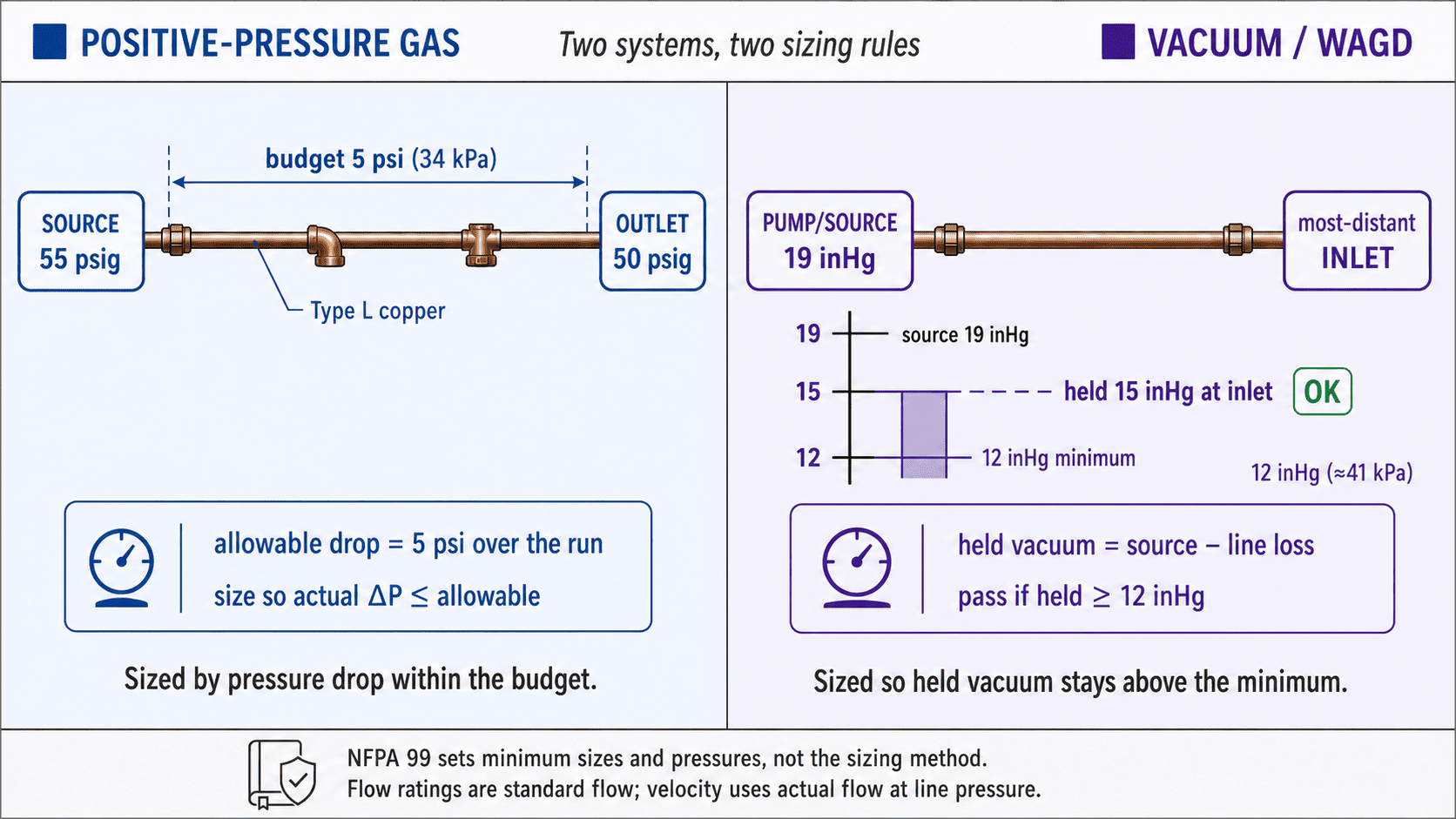
Positive-pressure gas is sized by pressure drop within the budget; vacuum is sized so the held vacuum stays above the minimum at the most distant inlet.
What to Look at First
- Required size — the selected pipe nominal size meeting both the hydraulic and the NFPA 99 minimum criteria
- Driven-to-Min badge — when it appears, the code minimum governs, not pressure-drop hydraulics
- Candidate pass/fail ratio — enter a specific pipe to confirm its total pressure drop or held vacuum against your allowable
How to Use
Choose System Type: Positive-pressure gas or Vacuum/WAGD. The two paths produce different outputs.
Pick the gas (positive mode) or vacuum sub-type (vacuum mode). This sets default pressures and per-outlet flow.
Set Segment Type — Main/Branch, Outlet Drop, or Vacuum/WAGD Branch. This controls the NFPA 99 minimum size.
Enter demand: use Direct Design Flow if you already have one, or switch to Build from Outlets to enter outlet count and area type for automatic diversity application.
Enter the run length. Leave Equivalent-Length Factor at 1.50 (the common 50 % fitting allowance) or enter a known equivalent length directly.
Confirm pressures. Positive systems default to 55 psig source, 50 psig delivery, 5 psi allowable drop. Vacuum defaults to 19 inHg source, 12 inHg minimum at the most distant inlet.
Optional — enter a Candidate Pipe Size to get a pass or fail verdict. Without one, the tool returns the required size only.
Read the result: three sizing values (hydraulic, profile minimum, selected), plus the pressure drop or held vacuum in the transparency block.
Size each segment using the design flow downstream of that segment only, not the whole-facility demand. The 6 SCFM / 3-second figure in NFPA 99 is a verification test criterion, not a per-outlet design flow.
Inputs & Outputs
Inputs
System Configuration
Sizing Parameters
Outputs
Results
Formula
Pressure: gauge → absolute
P_atm = 14.696 psia (101.325 kPa)
Positive:  P_abs = P_gauge + P_atm            55 psig → 69.70 psia
Vacuum:    P_abs = P_atm − vacuum_gauge        19 inHg → 5.36 psia
           held_vacuum = P_atm − P_abs_inlet   report in inHg
Demand
Connected load = Σ (outlets × per-outlet flow)    [standard flow]
Design flow    = connected load × diversity factor
  OR/ER = 1.00 (no diversity)   general inpatient ≈ 0.10 (illustrative — confirm against project basis)
Equivalent length and allowable loss
L_equiv  = L_actual × 1.50     (or direct equivalent)
allowable per 100 = ΔP_allow / (L_equiv / 100)
example: 5 psi over 400 ft equiv → 5 / 4 = 1.25 psi/100 ft
Also require actual total ΔP ≤ ΔP_allow
Friction pressure drop (Darcy–Weisbach, average absolute pressure)
P_avg = (P_in_abs + P_out_abs) / 2
ρ_line  = ρ_std × (P_avg / P_std)        from gas profile
Q_act   = Q_std × (P_std / P_avg)        standard → actual
V       = Q_act / A          A = π/4 · ID²   (actual bore)
Re      = ρ_line · V · ID / μ
f       = Darcy factor — Swamee–Jain, copper ε = 1.5 µm
ΔP/L    = f · (1/ID) · (ρ_line · V² / 2)
If ΔP > ~10% of P_in → iterate on P_out until convergence
Use Darcy friction factor (= 4 × Fanning factor)
Vacuum path — ρ and Q evaluated at sub-atmospheric average; actual volume much larger than standard.
Three sizing values
Hydraulic required  = smallest Type L where ΔP/100 ≤ allow AND total ΔP ≤ allow
Profile minimum     = ½ in (main/branch/outlet drop) or ¾ in (vacuum)
Selected required   = max(hydraulic, minimum)
Candidate check ratios (color bands)
Positive: ratio = actual ΔP / allowable ΔP
Vacuum:   ratio = predicted loss / available budget (verdict = held ≥ min)
ratio ≤ 0.90         ADEQUATE        green
0.90 < ratio ≤ 1.00  ADEQUATE AT LIMIT  amber
1.00 < ratio ≤ 1.15  UNDERSIZED, MARGINAL  orange
1.15 < ratio ≤ 1.50  UNDERSIZED         orange-red
ratio > 1.50         SIGNIFICANTLY UNDERSIZED  red
Type L copper internal diameters (ASTM B819)
½ in:  0.545 in  (13.84 mm)
¾ in:  0.785 in  (19.94 mm)
1 in:  1.025 in  (26.04 mm)
1¼ in: 1.265 in  (32.13 mm)
1½ in: 1.505 in  (38.23 mm)
2 in:  1.985 in  (50.42 mm)
2½ in: 2.465 in  (62.61 mm)
3 in:  2.945 in  (74.80 mm)
Metric conversions
1 psi = 6.89476 kPa
1 inHg = 3.38639 kPa = 0.4912 psi
1 SCFM = 28.3168 NL/min
1 ft = 0.3048 m
1 in = 25.4 mm
What Flow Demand, Diversity, and Equivalent Length Mean
Connected load and design flow. Connected load is the sum of every outlet's rated flow on the segment, as if all ran at once. Real systems rarely do, so a diversity factor scales the load down to a realistic peak. Operating rooms and emergency areas use a factor of 1.00 because they can all be in use together. General inpatient areas use a much lower factor, often around 0.10. Design flow is connected load times the factor.
Equivalent length. Fittings, valves, and bends add resistance beyond the straight run. The common shortcut adds 50 percent to the measured length, so a 60 foot run becomes 90 equivalent feet. Where you have a detailed fitting takeoff, enter the equivalent length directly instead.
Allowable friction loss. The system has a pressure budget, usually 5 psi for positive gases. Spread that budget over the equivalent length to get an allowable loss per 100 feet, which is what you size against.
Gauge versus absolute, and standard versus actual flow. Gas density depends on absolute pressure, so 55 psig becomes 69.7 psia in the math. Flow ratings are standard flow, but velocity inside the pipe uses actual flow at line pressure, which is much smaller for a compressed gas and much larger for vacuum.
Key Facts
- NFPA 99 governs medical gas materials, installation, and testing, but it does not provide a pipe-sizing method. Sizing is an engineering design practice.
- A medical-surgical vacuum inlet is designed to draw 3 SCFM (85 NL/min) while holding at least 12 inHg of vacuum at any adjacent inlet.
- The NFPA 99 figure of 6 SCFM for 3 seconds is a transient test criterion for oxygen and medical air outlets, not a per-outlet design flow.
- NFPA 99 sets the minimum size of mains and branches at ½ inch, and vacuum piping at ¾ inch, with ½ inch drops to individual inlets permitted.
- Positive-pressure gases other than instrument air are delivered at 50 psig, with the source set near 55 psig so the piping loss can be about 5 psi. Instrument air commonly runs at 175 psig.
- Equivalent length is often taken as the measured run plus 50 percent for fittings.
- ASTM B819 covers Types K and L specially cleaned seamless copper tube for medical gas systems, installed per NFPA 99. It is not interchangeable with ordinary plumbing or refrigeration copper.
- Diversity varies by area. Surgery and similar predetermined areas use no diversity, while a patient room inlet may be based on about 1 SCFM.
Applications
- Hospital and clinic mechanical design teams sizing distribution mains, risers, and branches
- Medical gas installers and estimators running a fast screen before pricing copper
- Renovations and expansions that add outlets and push an existing branch past its limit
- Checking whether an existing line can carry a new operating room or ICU zone
- Facilities and ASHE planning work where a documented flow and pressure basis is needed
- Preparing the demand and pressure-drop basis that a sealed design will later formalize
Example Calculation
Example 1: Oxygen branch, four operating-room outlets
Given: 4 oxygen outlets at 1.0 SCFM each, OR diversity 1.00, 60 ft run, source 55 psig, delivery 50 psig, allowable drop 5 psi.
Connected load = 4 × 1.0                = 4.0 SCFM
Design flow    = 4.0 × 1.00             = 4.0 SCFM
Equivalent len = 60 × 1.50              = 90 ft
Allowable/100  = 5 ÷ (90/100)          = 5.56 psi/100 ft (total cap 5 psi)
Absolute line  = 55 + 14.696           = 69.70 psia
Actual flow    = 4.0 SCFM × 14.696/69.70 ≈ 0.84 ACFM
Hydraulic size = below ½ in at this low flow
Profile min    = ½ in (branch)
Selected size  = ½ in Type L → DRIVEN TO MIN SIZE
Result: pressure drop is not the constraint here. The branch is set to the ½ inch code minimum, not by hydraulics.
Example 2: Medical-surgical vacuum branch
Given: source 19 inHg, minimum 12 inHg required at the most remote inlet, 3.0 SCFM per-inlet, 60 ft run.
Budget         = 19 − 12               = 7 inHg
Source abs     = 14.696 − (19 × 0.4912) = 5.36 psia
Design flow    = 3.0 SCFM (single inlet, diversity 1.00)
Equivalent len = 60 × 1.50             = 90 ft
If predicted loss on the selected size is 4 inHg → held vacuum = 15 inHg ≥ 12 inHg → ADEQUATE. If predicted loss is 8 inHg → held vacuum = 11 inHg < 12 inHg → UNDERSIZED.
Standards & References
- NFPA 99, Health Care Facilities Code — Governs installation, materials, minimum sizes, operating and test pressures for medical gas systems
- ASTM B819, Seamless Copper Tube for Medical Gas Systems (Types K and L) — Standard specification for oxygen-cleaned seamless copper tube for medical gas systems
- ISO 7396-1:2016, Medical Gas Pipeline Systems — International standard for compressed medical gases and vacuum pipeline systems
- Sizing Medical Gas Piping, Plumbing & Mechanical — Industry design-method reference (not a governing code)
- ASSE Series 6010 (medical gas personnel certification), CGA G-4.1 (oxygen cleaning), UK HTM 02-01, Canada CSA Z7396.1 — referenced by name for their respective scopes and jurisdictions
Limitations
- Sizes one segment at a time — a full system is a network; apply to each segment using downstream demand only
- Does not size the source, manifold, bulk or reserve supply, compressors, dryers, vacuum pumps, or receivers
- Does not verify oxygen cleaning, brazing or nitrogen purge, valves, zone or area alarms, or NFPA 99 test pressures
- Does not evaluate facility risk category, NFPA 99 system category, gas purity, dew point, or particulate limits
- Does not address cross-connection, standing-pressure, or verifier testing, seismic bracing, support spacing, or labeling
- Assumes Type L copper and ideal-gas, low-pressure-drop approximation on a US/NFPA basis (v1)
- Laboratory, dental, non-US jurisdictions, and multi-branch longest-run network analysis deferred to future versions
- Output is a design screen — a qualified medical gas designer or engineer must prepare and review the final design
Common Mistakes to Avoid
- Using the 6 SCFM for 3 seconds test figure as a per-outlet design flow — it is a verification criterion, not a demand value
- Feeding gauge pressure into the gas density calculation — density depends on absolute pressure, so 55 psig must become 69.7 psia
- Sizing one segment for the entire facility demand — each segment carries only the flow downstream of it
- Treating a vacuum reading in inHg as an absolute pressure — convert it, then report held vacuum back as a gauge value
- Using the nominal pipe size as the bore — friction depends on the actual internal diameter from the copper schedule
- Mixing the Darcy and Fanning friction factors — they differ by a factor of four
- Ignoring the NFPA minimum sizes — hydraulics may allow a smaller pipe, but the code floor governs
- Specifying ordinary plumbing or refrigeration copper — medical gas piping must be oxygen-cleaned tube to ASTM B819
Frequently Asked Questions
Does NFPA 99 give a pipe-sizing table?
What pressures do medical gas systems run at?
Why can't I size the whole hospital in one shot?
What is the minimum medical gas pipe size?
Should I use the 6 SCFM, 3-second figure as my design flow?
Why does a vacuum line need larger pipe than an oxygen line?
What copper is used for medical gas?
Can I build my final design from this calculator?
Frequently Used Together
Engineers often use these calculators in combination for complete project workflows:
Related Calculators
Explore similar calculators that might be useful for your project:
Plumbing Quick Reference — Keep It On Your Phone On Site
A 10-page field reference for catching pressure, velocity, slope, and pump-sizing mistakes before you order pipe, close a wall, or add a booster.
- Velocity limits, fixture pressure minimums, drain slope, and the 80 psi ceiling in one table
- Worked examples that show why a single pressure number gives four different answers
- Keep it on your phone, or print the two field-check pages
Free PDF. Calculators stay free. Unsubscribe anytime.
Calculate
e.g. 4.0 SCFM for 4 OR oxygen outlets at 1.0 SCFM each
e.g. 60 ft (measured pipe length, fittings added via factor)
1.50 (50% fitting allowance; 1.30–2.00 typical) — blank = 1.50 default
e.g. 55 psig (O₂/Air); 190 psig (Instrument Air) — blank = gas default
e.g. 50 psig (O₂/Air); 175 psig (Instrument Air) — blank = gas default