Pipe Support Spacing Calculator — Maximum Span by Stress and Deflection
On this page
Calculate
OD and wall from ASME B36.10M. I and Z computed from these.
e.g. 2 (in) or 50 (mm). Leave blank if uninsulated.
e.g. 12 lb/ft³ for mineral wool, 6 lb/ft³ for calcium silicate. Required if insulation thickness is entered.
e.g. 1.0 lb/ft for aluminum jacketing. Leave blank if none.
e.g. 0.25 (default). Leave blank to use 0.25 × Sh.
e.g. 29,000,000 psi / 200,000 MPa. Leave blank to use profile default.
e.g. 30 ft / 9.0 m. Enter to check a specific proposed spacing against stress and sag limits.
Overview
Pipe support spacing depends on two independent limits: one keeps the bending stress at the supports below an allowable, and the other keeps the midspan sag below a deflection limit. The maximum spacing is whichever you hit first. This calculator finds both the stress-limited span and the deflection-limited span, then reports the smaller one and which criterion governed.
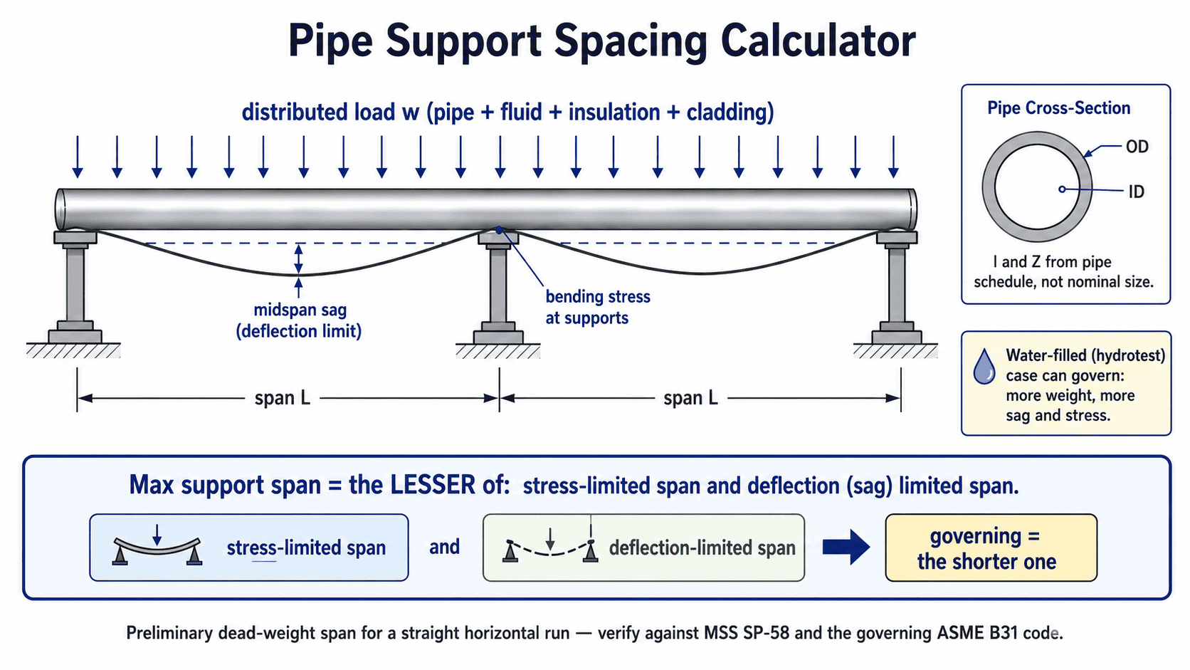
Maximum pipe support spacing is the lesser of the stress-limited span and the deflection-limited span; a water-filled line sags more and can govern at hydrotest.
What to Look at First
The Max Allowable Span is the key result, the lesser of two independent limits: the stress-limited span and the deflection-limited span. The Governing Criterion row tells you which one controls. Look at the load breakdown to see how pipe weight, contents, insulation, and cladding each contribute. If you entered a candidate span, the Stress Ratio and Sag Ratio rows show how close you are to each limit.
How to Use This Calculator
Select unit system (US or Metric), pipe material, and the pipe size and schedule from the dropdown. The schedule determines the wall thickness, OD, and from those the moment of inertia I and section modulus Z.
Choose the load case: Empty, Water-filled (operating), Hydrotest, or Custom fluid. Add insulation thickness and density if the line is insulated. Add cladding weight per length if applicable.
Set the stress allowable basis (factor × Sh, 5000 psi CS preset, or manual) and the deflection limit basis (B31.1/MSS, B31.3, L/240, or manual). Accept the defaults for standard carbon-steel gravity spans.
Click Calculate. Read the maximum allowable span and which criterion governs — stress or deflection.
Optional: enter a candidate span to check whether your proposed spacing passes both stress and sag limits, with separate ratios for each.
Place a support next to concentrated weights such as valves and flanges; the span table does not apply at those points.
Inputs & Outputs
Inputs
Outputs
Formula
Pipe Support Spacing Formulas
All canonical units must be applied before computing (see below). Never feed lb/ft or kg/m directly into the span formulas.
Canonical Units
US:     w in lb/in,  Z in in³,  I in in⁴,  Sall in psi,  E in psi,  L in in → display ft
Metric: w in N/mm,   Z in mm³,  I in mm⁴,  Sall in MPa,  E in MPa,  L in mm → display m
Section Properties (from OD and wall in the pipe schedule)
I = π/64 × (OD⁴ − ID⁴)
Z = 2·I / OD   (= I / (OD/2))
Distributed Load Build-up
w = w_pipe + w_fluid + w_insulation + w_cladding
w_pipe = ρ_pipe × π/4 × (OD² − ID²)
w_fluid = ρ_fluid × π/4 × ID²        (zero for empty case)
Metric: convert mass per length (kg/m) to force per length (N/mm) before computing spans:
w [N/mm] = (mass/length [kg/m]) × 9.807 / 1000
Stress-Limited Span
Bending moment over continuous supports: M = w·L²/10
Bending stress: σ = M/Z
Solve for L:
L_stress = sqrt( 10 · Z · Sall / w )
Deflection-Limited Span
Sag formula (conservative simply-supported): δ = 5·w·L⁴ / (384·E·I)
Fixed δ_allow (fourth-root solution):
L_defl = ( 384 · E · I · δ_allow / (5 · w) )^(1/4)
Span-dependent limit L/240 (δ_allow = L/240) — separate cubic-root branch:
5·w·L⁴/(384·E·I) = L/240 → L³ = 384·E·I / (5 × 240 × w) (cubic root)
The L/240 branch gives a different result from the fourth-root form. Treating L/240 as a fixed sag and using the fourth-root formula is a common mistake.
Governing Span
L_max = min( L_stress , L_defl )
Governing = whichever produced L_max
Candidate Check
stress_ratio = (w · L_cand² / (10 · Z)) / Sall
sag_ratio    = (5 · w · L_cand⁴ / (384 · E · I)) / δ_allow
                 (for L/240: δ_allow = L_cand/240)
Pass if L_cand ≤ L_max; first limit reported is max(stress_ratio, sag_ratio).
Natural Frequency (screening)
f₁ ≈ (π/2) · sqrt( E·I / (m · L_max⁴) )      Hz
US:     m = w / 386.09  (in/s²)
Target: f₁ > 4 Hz near rotating equipment.
Pipe Support Spacing Calculator
Put a support too far from the next one and a pipe does two bad things: it sags in the middle, and the bending stress at the supports climbs. The maximum spacing is whichever of those two limits you hit first. This calculator finds both the stress-limited span and the deflection-limited span, then reports the smaller one as the answer, along with which limit governed. It applies to a straight horizontal run with reasonably regular spans.
The load is the pipe's own dead weight plus whatever it carries: the fluid inside, the insulation, and any cladding. A water-filled line sags far more than the same line full of gas, which is why an empty gas line still has to be checked at hydrotest when it is filled with water. The tool builds up that distributed load, computes the section properties from the actual pipe schedule, and works in US or metric units.
One point of honesty about the beam model. A pipe running over a row of supports behaves as a continuous beam, not a single simply-supported span, so the bending stress uses the continuous-span coefficient wL²/10. The deflection is checked with the simply-supported sag formula, which overstates the sag for a continuous run and therefore lands on the safe side. This is a preliminary dead-weight span, not a full pipe-stress analysis, and it does not replace the support spacing in MSS SP-58 or the governing ASME B31 code.
Operating Load vs Hydrotest Load
A line that runs empty or gas-filled in service is much lighter than the same line full of water. During a hydrotest the pipe is filled with water, and that added weight increases both the bending stress and the sag. A spacing that passes in operation can fail when the line is filled. For any line that will be hydrotested, check the water-filled case and use the shorter governing span.
Continuous Beam vs Simply Supported Span
A single beam resting on two end supports is simply supported, with a midspan moment of wL²/8 and a relatively large sag. A pipe over a row of evenly spaced supports is different: each span is partially restrained by its neighbours, so it behaves as a continuous beam. The continuous-span bending moment is wL²/10, lower than the simply-supported value, which is the coefficient used for the stress check here. For deflection, this tool keeps the simply-supported sag formula, which overstates the sag of a continuous run and therefore gives a conservative, safe-side deflection span.
What Governs the Span: Stress or Sag
The stress check and the deflection check are separate calculations on the same load. The maximum spacing is the smaller of the two spans. Knowing which one governs tells you what to change for a longer span: a heavier schedule helps a stress-governed span, while a stiffer or shallower deflection target moves a sag-governed one.
Light, small-bore pipe tends to be deflection-governed, where the sag limit bites before the stress does. Large or heavy pipe, especially water-filled, tends to be stress-governed. The crossover depends on size, schedule, contents, and the limits chosen, which is why both are always computed and compared.
Pipe Schedule, I and Z
The nominal size is only a label for selecting the pipe. The numbers that drive the span come from the schedule: the outside diameter, the wall thickness, and from those the inside diameter, the moment of inertia I, and the section modulus Z. I controls the sag, since deflection depends on it directly. Z controls the stress, since bending stress is the moment divided by Z. A heavier schedule on the same nominal size has more metal, a larger I and Z, and so allows a longer span. Using nominal values instead of schedule values gives the wrong section properties and the wrong span.
Key Facts
- The maximum support span is the lesser of a stress-limited span and a deflection-limited span.
- Bending over continuous supports uses the moment coefficient wL²/10, not the wL²/8 of a single simply-supported span.
- A common deflection limit is 0.1 inch or half the pipe diameter, whichever is smaller; some practices use L/240.
- A common screening bending-stress limit for carbon-steel gravity spans is about a quarter of the code allowable (Sh/4), often near 5000 psi for common carbon-steel cases.
- A water-filled line sags much more than a gas-filled one, so spans must be re-checked at hydrotest.
- Span is set by the actual moment of inertia and section modulus from the pipe schedule, not by the nominal size label.
- Small-bore pipe is usually deflection-governed; large or heavy pipe is usually stress-governed.
- The calculator gives support spacing, not hanger or structural attachment design. Natural frequency above about 4 Hz is a common screening target near rotating equipment.
Applications
- Laying out hanger and support spacing for straight horizontal pipe runs
- Checking an existing layout against stress and sag limits before a modification
- Comparing empty, operating, and hydrotest load cases on the same line
- Setting spacing for insulated steam, condensate, and hot-water mains
- First-pass spacing for water, chilled-water, and process lines ahead of detailed support and stress review
- A preliminary check of MSS SP-58 span-table values against project-specific loads
Example Calculation
Example 1: Deflection-governed span (large line)
Given: 24 inch Schedule 40 carbon steel (A53-B), moment of inertia 3421 in⁴ (from schedule), distributed load 170.9 lb/ft, modulus 29.4 million psi, deflection limit 0.1 inch.
w = 170.9 lb/ft = 14.24 lb/in
L_defl = ( 384 × 29.4e6 × 3421 × 0.1 / (5 × 14.24) )^(1/4)
       = ( 3.86e12 / 71.2 )^(1/4)
       ≈ 482.6 in = 40.2 ft
Result: the deflection limit allows about 40.2 ft. This is close to, and slightly under, the roughly 42 ft in the B31.1 and MSS span tables.
Example 2: Stress-governed span (lighter line)
Given: section modulus 8.495 in³ (NPS 6 × Sch 40), distributed load 3.475 lb/in, stress allowable 5000 psi.
L_stress = sqrt( 10 × 5000 × 8.495 / 3.475 )
         = sqrt( 424,750 / 3.475 )
         = sqrt( 122,230 ) ≈ 349 in = 29.1 ft
Result: the stress limit allows about 29 ft. If the deflection-limited span for this line is longer, stress governs and 29 ft is the maximum spacing.
Example 3: Candidate span check
Given: governing maximum span of 29 ft (stress-limited), proposed candidate 35 ft.
stress_ratio = (35 / 29)² = 1.46 → over stress limit by 46 percent
sag_ratio    = also computed at 35 ft; stress ratio controls
Verdict: OVER-SPAN — stress governs. The candidate must come in or the pipe needs a heavier schedule.
Example 4: Operating vs hydrotest (6 inch gas line)
Given: NPS 6 × Sch 40 carbon steel (OD 6.625 in, ID 6.065 in), pipe weight 18.97 lb/ft. Compare empty (gas, negligible fluid weight) with water-filled hydrotest.
Empty:        w ≈ 18.97 lb/ft = 1.581 lb/in
  L_defl = ( 384 × 29e6 × 28.1 × 0.1 / (5 × 1.581) )^(1/4) ≈ 504 in = 42.0 ft

Hydrotest:    w ≈ 18.97 + 12.5 = 31.5 lb/ft = 2.625 lb/in
  L_defl = ( 384 × 29e6 × 28.1 × 0.1 / (5 × 2.625) )^(1/4) ≈ 453 in = 37.8 ft
Filling the line with water drops the deflection-limited span from 42 ft to 38 ft. The hydrotest case governs — spacing should be set for the water-filled condition.
Example 5: L/240 deflection limit
For the L/240 basis, substitute δ_allow = L/240 into the sag formula:
5·w·L⁴ / (384·E·I) = L/240
L³ = 384·E·I / (5 × 240 × w)    → solve the CUBE root, not the fourth root
Using the fourth-root formula with a fixed δ gives the wrong answer for L/240.
Standards & References
- ANSI/MSS SP-58: Pipe Hangers and Supports: Materials, Design, Manufacture, Selection, Application, and Installation. Table 4 gives maximum support spacing for horizontal pipe.
- ASME B31.1: Power Piping. Table 121.5 gives suggested support spacing for horizontal steel pipe.
- ASME B31.3: Process Piping. Para 302.3.5 covers sustained-load longitudinal stress.
- ASME B36.10M: Welded and Seamless Wrought Steel Pipe. Referenced for OD, wall thickness, and section properties used in the pipe size lookup.
- ASTM B88: Standard Specification for Seamless Copper Water Tube. Referenced for copper tube OD and wall thickness (Type K and Type L).
Limitations
- Preliminary dead-weight span for a straight horizontal run with reasonably regular spans; not a code stress analysis and not the full ASME sustained-stress check.
- Uniform distributed load only. A concentrated valve or flange load requires separate treatment; place a support next to concentrated weights.
- Does not include longitudinal pressure stress, thermal expansion or restraint of thermal movement, seismic, wind, water-hammer, or dynamic loads beyond the optional frequency screen.
- Does not cover risers and vertical runs, end spans, spans next to anchors or equipment, unequal spans, or branch nodes — all of which can require shorter spacing.
- Does not check pipe slope or drainage requirements, which sag can compromise on condensate and gravity-drained lines.
- Does not evaluate local stresses at shoes, clamps, U-bolts, saddles, or point-contact supports, and does not check insulation crushing, vapor-barrier damage, or cold-pipe thermal breaks at supports.
- Does not size the supports, hangers, rods, or structural steel; the support reaction shown is an estimate only.
- Natural frequency is a first screening estimate using beam theory; detailed vibration analysis may be required near rotating equipment.
- E and Sh are at the material profile reference temperature. Verify against temperature-derated values for elevated-temperature service.
- Deflection check uses the conservative simply-supported formula. True continuous-span sag is smaller.
- Verify against MSS SP-58, the governing ASME B31 code, and a qualified engineer before finalizing support layout.
Common Mistakes to Avoid
- Checking only stress or only sag. The maximum span is the lesser of the two, and the governing one changes with pipe size and contents.
- Using the simply-supported moment wL²/8 for a run over many supports. Continuous spans use wL²/10.
- Feeding load in lb/ft straight into the formula. The span equations need load per length in lb/in; using lb/ft puts the answer off by a factor of twelve.
- Sizing for operating weight on a line that will be hydrotested with water. The water-filled case is heavier and usually governs.
- Using the nominal size for section properties. The moment of inertia and section modulus come from the actual OD and wall in the schedule.
- Treating L/240 as a fixed sag. Because the limit depends on the span, it gives a span-based cubic-root equation, not the fixed-limit fourth-root form.
- Using the same spacing near anchors, equipment, and branches. End spans and spans next to anchors, equipment, or branch connections can need separate checks.
- Assuming the spacing result sizes the hanger. Spacing is not hanger design; rods, clamps, shoes, anchors, and structural attachments need their own load checks.
- Reading the result as code compliance. It is a preliminary screen; MSS SP-58 and the governing B31 code still apply.
Frequently Asked Questions
What sets the maximum pipe support spacing?
Why use wL²/10 instead of wL²/8 for the bending moment?
Does the calculator check sag and stress separately?
Why do I have to re-check spans at hydrotest?
What deflection limit should I use?
Can I use this for vertical pipe or risers?
Does this include valves and flanges?
Does the calculator size the hangers and supports themselves?
Frequently Used Together
Engineers often use these calculators in combination for complete project workflows:
Related Calculators
Explore similar calculators that might be useful for your project:
Plumbing Quick Reference — Keep It On Your Phone On Site
A 10-page field reference for catching pressure, velocity, slope, and pump-sizing mistakes before you order pipe, close a wall, or add a booster.
- Velocity limits, fixture pressure minimums, drain slope, and the 80 psi ceiling in one table
- Worked examples that show why a single pressure number gives four different answers
- Keep it on your phone, or print the two field-check pages
Free PDF. Calculators stay free. Unsubscribe anytime.
Calculate
OD and wall from ASME B36.10M. I and Z computed from these.
e.g. 2 (in) or 50 (mm). Leave blank if uninsulated.
e.g. 12 lb/ft³ for mineral wool, 6 lb/ft³ for calcium silicate. Required if insulation thickness is entered.
e.g. 1.0 lb/ft for aluminum jacketing. Leave blank if none.
e.g. 0.25 (default). Leave blank to use 0.25 × Sh.
e.g. 29,000,000 psi / 200,000 MPa. Leave blank to use profile default.
e.g. 30 ft / 9.0 m. Enter to check a specific proposed spacing against stress and sag limits.