Vacuum Pipe Sizing Calculator — Size Vacuum Lines by ACFM, Velocity, and Allowable Pressure Drop
On this page
Calculate
Sets default velocity limits and allowable pressure-drop targets. Medical-Surgical applies NFPA 99 parameters (19 inHg source, 12 inHg min at inlet, 7 inHg total allowable).
Main lines default to 6,000 fpm velocity limit; branch lines to 4,000 fpm. Medical profile uses 5,000 fpm for both.
Design flow at standard conditions (14.696 psia / 101.325 kPa). Leave blank to use Inlet Build-Up fields below instead.
Used only when Design Flow is left blank. Enter the count of vacuum inlets served by this pipe run.
Rated vacuum demand per inlet at standard conditions. Medical-surgical inlets: 3 SCFM (85 sL/min) each.
Fraction of inlets expected to operate at once (0 to 1). Default 1.0 means no diversity, all inlets active. Use 0.50 for general lab, 0.25 for dental.
Vacuum held at the pump (gauge below atmospheric). Medical-surgical: typically 19 inHg. General lab: 10–20 inHg. High vacuum: 25–29 inHg.
Total equivalent pipe length including straight pipe and all fittings. Add 30–50% to straight run for a typical fitting allowance.
Steel Sch 40 for industrial/lab. Copper Type L or K for medical gas (ASTM B819 cleaning required). PVC for low-pressure or chemically resistant systems.
Maximum allowable gas velocity. Defaults: General main 6,000 fpm, branch 4,000 fpm; Medical/Dental 5,000 fpm. Leave blank to use the profile default.
General/Lab: allowable friction loss per 100 ft (default 0.30 inHg/100 ft). Medical-Surgical: total allowable loss for the run (default 7.0 inHg, from 19 inHg source to 12 inHg minimum). Leave blank for the profile default.
Air temperature in the pipe, used to correct air density and EAR. Leave blank to use 60 °F / 15.6 °C standard.
Local atmospheric pressure at site elevation. Default is sea-level standard (29.92 inHg / 101.325 kPa). Enter a lower value for high-altitude installations.
Overview
Vacuum pipe sizing determines the minimum pipe diameter that keeps gas velocity and friction pressure drop within acceptable limits from the pump inlet to the most remote vacuum outlet. Under-sized vacuum pipe starves outlets during peak use: the held vacuum falls below the minimum and equipment cannot operate. Over-sized pipe wastes copper or steel and creates dead-leg pockets that trap condensate and contamination.
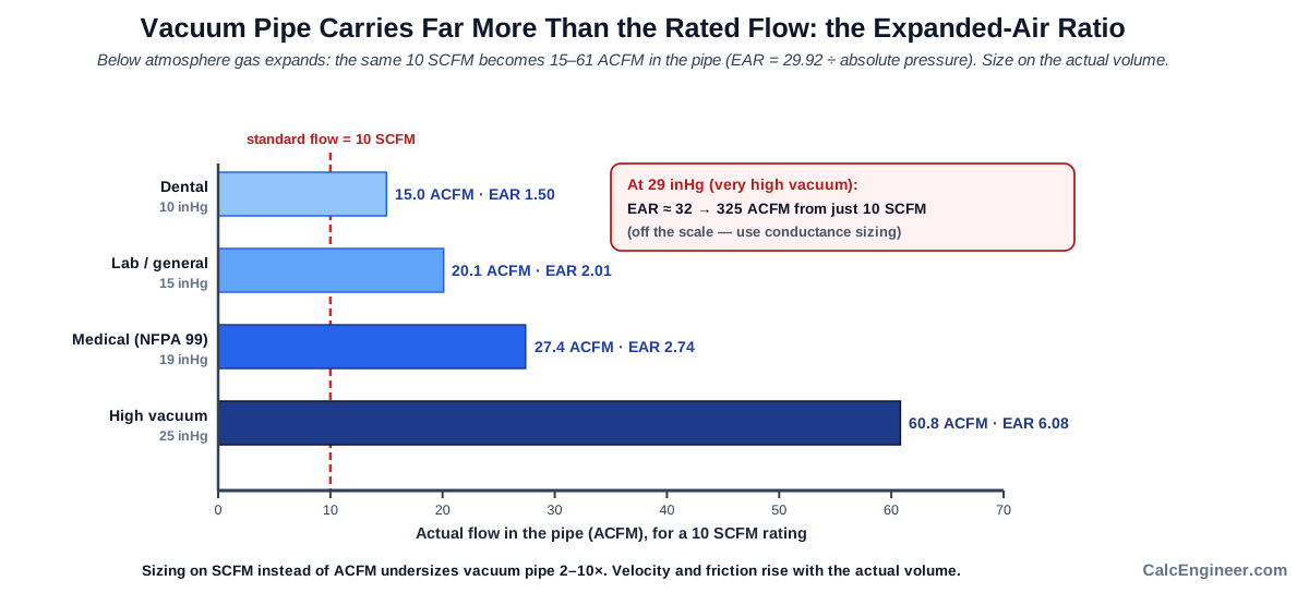
What makes vacuum pipe sizing fundamentally different from water or compressed-air pipe sizing is the sub-atmospheric expansion of the gas. At 15 inHg vacuum (absolute pressure roughly 14.9 inHg), atmospheric air expands by a factor of about 2.0 before entering the pipe. At 25 inHg vacuum, that expansion factor rises to about 6. This means the actual volume flowing through the pipe, and therefore the velocity, is far higher than the standard flow rate suggests. A calculator that ignores this expansion will seriously underestimate velocity and pressure drop and select pipe that is undersized.
This calculator uses the Darcy-Weisbach friction equation with a rigorous sub-atmospheric expansion correction: the design flow (SCFM or sL/min) is multiplied by the Expanded Air Ratio (EAR = 29.92 / P_abs × (460 + T) / 520) to get the actual cubic feet per minute in the pipe. Three system profiles are supported: General/Lab (utility vacuum), Medical-Surgical (NFPA 99), and Dental/Low Vacuum, each with appropriate default velocity limits and allowable pressure-loss targets. Four pipe materials are covered: Steel Schedule 40 (ASME B36.10), Copper Type L and Type K (ASTM B88), and PVC Schedule 40 (ASTM D1785).
Size mode and Check mode are both supported. Size mode selects the smallest standard pipe that satisfies both the velocity limit and the pressure-drop limit, reporting which constraint governs. Check mode takes a pipe you specify and returns PASS, MARGINAL, or FAIL with the binding criterion and utilization ratio. Imperial (SCFM, inHg, ft) and Metric (sL/min, kPa, m) units are fully supported.
What to Look at First
Selected or checked pipe size. In SIZE mode the first output is the recommended nominal pipe size and material: the standard pipe that satisfies both the velocity and pressure-drop limits you entered (or the defaults). In CHECK mode it is the PASS / MARGINAL / FAIL verdict for the size you specified.
Binding criterion. The output reports whether velocity or pressure drop governs the selection. On long, high-vacuum runs pressure drop tends to govern; on short, high-flow runs velocity governs. Knowing which constraint is binding tells you where to focus if you need to reduce pipe size or tighten tolerances.
Expanded Air Ratio (EAR). The actual volume of gas flowing through the pipe is EAR times the standard flow. At 15 inHg vacuum (about 50% of atmospheric), EAR ≈ 2.1, meaning the actual volume is more than double the standard flow. This is the core compressibility correction that makes vacuum pipe sizing different from water pipe sizing.
Soft-check advisories. Review any advisory messages that appear below the main result. A compressibility advisory means the total friction loss exceeds 20% of absolute pressure and the incompressible Darcy model may underpredict losses; size up one pipe.
How to Use This Calculator
Select Calculation Mode: Size Pipe to find the recommended nominal pipe size; Check Existing Pipe to verify a pipe you already have.
Select Unit System (Imperial or Metric); all inputs and outputs switch accordingly.
Select the System Profile: General/Lab for utility vacuum, Medical-Surgical for NFPA 99 systems, or Dental for low-vacuum dental applications.
Select Line Type: Main or Branch. This sets the default velocity limit (mains 6,000 fpm, branches 4,000 fpm; medical both 5,000 fpm).
Enter Design Flow in SCFM (or sL/min in Metric). Alternatively, use the Inlet Build-Up fields to enter inlet count, per-inlet flow, and a simultaneous use factor; the calculator will compute the design flow automatically.
Enter Operating Vacuum (gauge) in inHg or kPa. This is the vacuum level held at the pump, not the drop across the pipe run.
Enter Equivalent Pipe Length (ft or m). Include straight pipe plus equivalent lengths for all fittings.
Select Pipe Material: Steel Sch 40, Copper Type L, Copper Type K, or PVC Sch 40.
In CHECK mode: select the Nominal Pipe Size to verify.
Optionally enter Velocity Limit and Allowable Pressure Loss to override the profile defaults.
Click Calculate. Read the selected or checked pipe size, binding criterion, velocity, pressure drop, and breakdown table.
The Medical-Surgical profile applies NFPA 99 pressure parameters (source 19 inHg, min inlet 12 inHg, total allowable 7 inHg). For final medical gas design the result must be reviewed by a qualified medical gas designer and verified by required NFPA 99 testing.
Inputs & Outputs
Inputs
Outputs
Formula
Calculator Formula
This calculator uses the Darcy–Weisbach equation with a sub-atmospheric expansion correction.
Step 1: Parse Vacuum and Absolute Pressure
P_abs = P_atm − V_gauge [inHg absolute]
Where:
- P_atm = atmospheric pressure (default 29.92 inHg)
- V_gauge = operating vacuum (inHg gauge below atmosphere)
Absolute pressure must be positive; the model is valid for P_abs ≥ 0.05 inHg (continuum flow).
Step 2: SCFM → ACFM Expansion (EAR)
EAR  = (29.92 / P_abs) × (460 + T_°F) / 520
ACFM = SCFM × EAR
EAR (Expanded Air Ratio) is the key correction. At 15 inHg vacuum (P_abs ≈ 14.9 inHg), EAR ≈ 2.0; the pipe carries twice the standard flow volume.
Step 3: In-Pipe Air Density
ρ = 0.0763 × (P_abs / 29.92) × (520 / (460 + T_°F)) [lb/ft³]
Step 4: Velocity
V_fpm = 183.3 × ACFM / D_in²
Where D_in is the pipe inside diameter in inches.
Step 5: Reynolds Number and Friction Factor
Re = ρ × (V_fpm/60) × (D_in/12) / μ
With μ = 1.24×10⁻⁵ lb/(ft·s) for air at standard conditions.
- Re < 2,300: laminar: f = 64 / Re
- Re ≥ 2,300: turbulent/transitional: Colebrook-White iteration:
1/√f = −2 log₁₀(ε/(3.7D) + 2.51/(Re√f))
Pipe roughness ε: Steel 0.00015 ft; Copper 5×10⁻⁶ ft; PVC 5×10⁻⁶ ft.
Step 6: Pressure Drop (Darcy–Weisbach)
ΔP [lb/ft²] = f × (L_eq / D_ft) × ρ × V_fps² / (2 × 32.174)
ΔP [inHg]   = ΔP_lbft2 / 70.73
Step 7: Utilization and Verdict
General/Lab and Dental profiles:
U = max(V_fpm / V_limit, ΔP_per100ft / allow_per100ft)
Medical-Surgical (total-loss mode):
U = max(V_fpm / V_limit, ΔP_total / allow_total)
| Utilization U | Verdict |
|---|---|
| U < 0.85 | PASS |
| 0.85 ≤ U < 1.00 | MARGINAL |
| U ≥ 1.00 (Check mode) | FAIL |
Pipe Inside Diameters
| Nominal | Steel Sch 40 | Copper L | Copper K | PVC Sch 40 |
|---|---|---|---|---|
| ½ in | 0.622 in | 0.545 in | 0.527 in | 0.602 in |
| ¾ in | 0.824 in | 0.785 in | 0.745 in | 0.804 in |
| 1 in | 1.049 in | 1.025 in | 0.995 in | 1.029 in |
| 1¼ in | 1.380 in | 1.265 in | 1.245 in | 1.360 in |
| 1½ in | 1.610 in | 1.505 in | 1.481 in | 1.590 in |
| 2 in | 2.067 in | 2.005 in | 1.959 in | 2.047 in |
| 2½ in | 2.469 in | 2.465 in | 2.435 in | 2.445 in |
| 3 in | 3.068 in | 2.945 in | 2.907 in | 3.042 in |
| 4 in | 4.026 in | 3.925 in | 3.857 in | 3.998 in |
| 6 in | 6.065 in | N/A | N/A | 6.031 in |
What Is Vacuum Pipe Sizing?
Vacuum pipe sizing is the engineering process of selecting the minimum pipe diameter that keeps actual gas velocity and friction pressure drop within acceptable limits across a vacuum distribution system. Unlike water or compressed-air pipe sizing, vacuum systems operate below atmospheric pressure, which causes the gas to expand as it travels toward the pump. That expansion raises the actual volumetric flow, and therefore the velocity and friction loss, well above what the standard flow rate implies. A pipe that looks adequate when sized on standard cubic feet per minute will often be seriously undersized when the sub-atmospheric volume expansion is correctly applied.
The core correction is the Expanded Air Ratio (EAR), which multiplies standard flow by the ratio of atmospheric pressure to absolute line pressure (adjusted for temperature). At 15 inHg vacuum, EAR is about 2.0; at 25 inHg vacuum, EAR rises to about 6.1. This means a 25 inHg vacuum line carrying 10 SCFM actually has about 61 ACFM flowing through the pipe: the velocity and friction loss must be calculated on about 61 ACFM, not 10 SCFM.
System Profiles and Design Limits
The calculator supports three system profiles that reflect common practice in different industries. The General/Lab profile applies to utility vacuum systems in laboratories, research facilities, and manufacturing plants. Default limits are 6,000 fpm for mains and 4,000 fpm for branches, with an allowable friction loss of 0.30 inHg per 100 equivalent feet, generous limits suited to systems where some vacuum variation is acceptable.
The Medical-Surgical profile follows NFPA 99 Health Care Facilities Code parameters: a source vacuum of 19 inHg, a minimum required vacuum at the most remote inlet of 12 inHg, and therefore a maximum allowable friction loss of 7 inHg for the entire piping run from pump to furthest outlet. Velocity is limited to 5,000 fpm. This profile operates in total-loss mode: the entire 7 inHg budget must not be exceeded across the full equivalent pipe length.
The Dental/Low Vacuum profile suits dental vacuum systems that typically operate at lower vacuum levels (8–12 inHg) with moderate velocity limits. Design parameters are similar to General/Lab but at lower operating pressure, which means higher EAR values and greater sensitivity to pipe undersizing.
SIZE Mode and CHECK Mode
In SIZE mode, the calculator iterates through the selected pipe material table from smallest to largest and selects the first standard nominal size that satisfies both the velocity limit and the pressure-drop limit. The result identifies the selected size, the binding criterion (whether velocity or pressure drop governed), and the utilization ratio at the selected size. A PASS verdict means both criteria are comfortably met (utilization below 85%). A MARGINAL verdict means both criteria are met but utilization is between 85% and 100%; the pipe passes but is near its limit.
In CHECK mode, the calculator applies all the same physics to the pipe size you specify and returns a PASS, MARGINAL, or FAIL verdict with the utilization ratio and binding criterion. FAIL means one or both design limits are exceeded at the current conditions. The output also shows the minimum compliant size if a failure is detected.
Key Facts
- At 15 inHg vacuum, air expands to about twice its standard volume before entering the pipe, so vacuum systems need substantially larger pipe than compressed air at comparable flow rates.
- The NFPA 99 medical-surgical vacuum standard requires a minimum 12 inHg at the most remote inlet, with the pump source set at 19 inHg, giving a 7 inHg allowable loss budget.
- Vacuum pipe friction loss increases with the square of velocity; doubling the actual flow requires reducing pipe length or jumping two nominal sizes.
- Copper Type L and Type K pipe for medical vacuum must meet ASTM B819 cleanliness requirements; ordinary plumbing copper is not acceptable in healthcare applications.
- PVC Schedule 40 is chemically resistant and often used for laboratory vacuum systems handling solvents, acids, or corrosive vapors that would attack copper or steel.
- The Colebrook-White equation used for turbulent friction factors requires iteration because friction factor appears on both sides of the equation; this calculator converges to 1×10⁻¹⁰ tolerance.
- Absolute pressure below about 1 inHg (≈ 3 kPa) approaches the transitional flow regime where continuum-fluid assumptions begin to fail; high-vacuum systems above 29 inHg require conductance-based sizing.
Applications
- Laboratory vacuum distribution mains and branches for vacuum filtration, rotary evaporation, and degassing workstations.
- Medical-surgical vacuum systems per NFPA 99 for operating rooms, ICUs, emergency departments, and general patient-care areas.
- Dental vacuum system piping for wet-ring and dry-vacuum systems in clinics and dental offices.
- Industrial vacuum systems for pick-and-place automation, thermoforming, and vacuum conveying.
- Checking whether existing vacuum piping can handle additional outlets or increased demand without violating velocity or pressure-drop limits.
- Sizing vacuum pipe for industrial drying and degassing chambers where maintained vacuum level is critical.
- Educational: demonstrating sub-atmospheric gas expansion and its effect on pipe sizing versus compressed-air or water systems.
Example Calculation
Example: SIZE Mode, General/Lab Profile (Imperial)
Given:
- Profile: General / Lab
- Line type: Main
- Design flow: 20 SCFM
- Vacuum (gauge): 15 inHg
- Atmospheric pressure: 29.92 inHg (default)
- Temperature: 60 °F (default)
- Equivalent length: 100 ft
- Material: Steel Sch 40
- Allowable loss: 0.30 inHg / 100 ft (default)
- Velocity limit: 6,000 fpm (default, main)
Step 1: Absolute pressure
P_abs = 29.92 − 15 = 14.92 inHg
Step 2: EAR and ACFM
EAR  = (29.92 / 14.92) × (460 + 60) / 520 = 2.005 × 1.000 = 2.005
ACFM = 20 × 2.005 = 40.1 ACFM
Step 3: Try 2 in Steel Sch 40 (ID = 2.067 in)
V = 183.3 × 40.1 / (2.067²) = 7,352 / 4.272 = 1,721 fpm   (< 6,000 ✓)
ρ = 0.0763 × (14.92/29.92) × 1.000 = 0.03804 lb/ft³
D_ft = 2.067/12 = 0.17225 ft
V_fps = 1721/60 = 28.7 fps
Re = 0.03804 × 28.7 × 0.17225 / 1.24e-5 = 15,150 (turbulent)
ε/D = 0.00015 / 0.17225 = 8.71×10⁻⁴
f ≈ 0.0293 (Colebrook)
ΔP_lbft2 = 0.0293 × (100/0.17225) × 0.03804 × 28.7² / (2×32.174) = 8.28 lb/ft²
ΔP_inHg  = 8.28 / 70.73 = 0.117 inHg over 100 ft
ΔP/100ft = 0.117 inHg/100 ft   (< 0.30 ✓)
Both criteria met. Utilization = max(1721/6000, 0.117/0.300) = max(0.287, 0.390) = 0.390 → PASS
Result: 2 in Steel Sch 40: pressure-drop-governed at 39% utilization.
Standards & References
- ASPE Design Handbook, Volume 2, Vacuum Systems: primary source for the SCFM to ACFM vacuum sizing method used on this page
- ASPE Pipeline: Proper Sizing for Vacuum Systems Is Crucial in Healthcare Facilities: article on vacuum system sizing for healthcare facilities
- Crane Co., Technical Paper No. 410 (TP-410): industry reference for Darcy-Weisbach pipe friction calculations; covers flow through valves, fittings, and pipe
- NFPA 99, Health Care Facilities Code: governs medical-surgical vacuum installation, materials, operating pressures, and testing requirements
- ASTM B88, Seamless Copper Water Tube: covers Type L and Type K copper tube inside diameters used in this calculator
- ASTM B819, Seamless Copper Tube for Medical Gas Systems: specifies oxygen-cleaned copper tube required for medical vacuum piping
- ASTM D1785, Poly(Vinyl Chloride) (PVC) Plastic Pipe: covers PVC Schedule 40 inside diameters used in this calculator
- ASME B36.10M: welded and seamless wrought steel pipe; source of Steel Schedule 40 inside diameters
- ASHRAE Handbook, HVAC Applications, Chapter 14 (Medical Facilities): design guidance for medical-gas and vacuum piping systems
Limitations
- This calculator sizes a single pipe segment; for a branched or looped vacuum system, apply it to each segment using the downstream demand for that segment only.
- The model assumes steady-state, single-phase gas flow. Liquid slugs, wet-ring pump seal water, and condensate carryover are outside scope.
- The continuum-flow (Darcy-Weisbach) model is valid down to about 0.05 inHg absolute pressure; below that, molecular-flow conductance sizing is required.
- When total friction loss exceeds 20% of absolute pressure, the incompressible Darcy model may underestimate losses; a compressibility advisory is shown and sizing up one pipe size is recommended.
- Air dynamic viscosity is held constant at 1.24×10⁻⁵ lb/(ft·s); for gases other than air or temperatures far from 60 °F, viscosity correction is needed.
- Pump capacity, receiver sizing, vacuum regulator losses, isolation valve losses, and trap or separator losses are not included; account for them separately.
- Final medical gas vacuum system design must be prepared by a qualified medical gas designer and verified by NFPA 99 required testing.
Common Mistakes to Avoid
- Sizing vacuum pipe on standard flow rate without applying the Expanded Air Ratio: this underestimates actual velocity and pressure drop by 2–10× depending on the vacuum level.
- Using gauge pressure instead of absolute pressure: the EAR calculation requires absolute pressure (atmospheric minus vacuum), not just the vacuum reading.
- Applying a single-pipe result to a branched or looped system: size each segment using only the downstream demand for that segment.
- Ignoring fitting equivalent lengths: a typical vacuum system run has 30–60% additional equivalent length in fittings, bends, and isolation valves.
- Exceeding the NFPA 99 medical vacuum maximum allowable loss of 7 inHg: the pipe must maintain at least 12 inHg at the most remote inlet with the pump at 19 inHg.
- Neglecting the compressibility advisory: when total friction loss exceeds 20% of absolute pressure, the incompressible Darcy model under-predicts losses and the pipe should be sized up.
- Using PVC pipe in medical gas or sterile vacuum applications: copper to ASTM B819 (oxygen-cleaned, nitrogen-purged) is required.
Frequently Asked Questions
Why does vacuum pipe sizing require larger pipe than compressed air at the same flow?
What is the Expanded Air Ratio (EAR) and why does it matter?
What are the NFPA 99 pressure parameters for medical-surgical vacuum?
How do I enter flow if I have multiple inlets rather than a known SCFM?
What velocity limit should I use for vacuum mains and branches?
What is the difference between gauge vacuum and absolute pressure?
Why can pressure drop govern even when velocity is acceptable?
Why does deeper vacuum need a larger pipe for the same SCFM?
What is the difference between Size mode and Check mode?
Frequently Used Together
Engineers often use these calculators in combination for complete project workflows:
Related Calculators
Explore similar calculators that might be useful for your project:
Plumbing Quick Reference — Keep It On Your Phone On Site
A 10-page field reference for catching pressure, velocity, slope, and pump-sizing mistakes before you order pipe, close a wall, or add a booster.
- Velocity limits, fixture pressure minimums, drain slope, and the 80 psi ceiling in one table
- Worked examples that show why a single pressure number gives four different answers
- Keep it on your phone, or print the two field-check pages
Free PDF. Calculators stay free. Unsubscribe anytime.
Calculate
Sets default velocity limits and allowable pressure-drop targets. Medical-Surgical applies NFPA 99 parameters (19 inHg source, 12 inHg min at inlet, 7 inHg total allowable).
Main lines default to 6,000 fpm velocity limit; branch lines to 4,000 fpm. Medical profile uses 5,000 fpm for both.
Design flow at standard conditions (14.696 psia / 101.325 kPa). Leave blank to use Inlet Build-Up fields below instead.
Used only when Design Flow is left blank. Enter the count of vacuum inlets served by this pipe run.
Rated vacuum demand per inlet at standard conditions. Medical-surgical inlets: 3 SCFM (85 sL/min) each.
Fraction of inlets expected to operate at once (0 to 1). Default 1.0 means no diversity, all inlets active. Use 0.50 for general lab, 0.25 for dental.
Vacuum held at the pump (gauge below atmospheric). Medical-surgical: typically 19 inHg. General lab: 10–20 inHg. High vacuum: 25–29 inHg.
Total equivalent pipe length including straight pipe and all fittings. Add 30–50% to straight run for a typical fitting allowance.
Steel Sch 40 for industrial/lab. Copper Type L or K for medical gas (ASTM B819 cleaning required). PVC for low-pressure or chemically resistant systems.
Maximum allowable gas velocity. Defaults: General main 6,000 fpm, branch 4,000 fpm; Medical/Dental 5,000 fpm. Leave blank to use the profile default.
General/Lab: allowable friction loss per 100 ft (default 0.30 inHg/100 ft). Medical-Surgical: total allowable loss for the run (default 7.0 inHg, from 19 inHg source to 12 inHg minimum). Leave blank for the profile default.
Air temperature in the pipe, used to correct air density and EAR. Leave blank to use 60 °F / 15.6 °C standard.
Local atmospheric pressure at site elevation. Default is sea-level standard (29.92 inHg / 101.325 kPa). Enter a lower value for high-altitude installations.