Fire Pump Performance Curve Calculator — NFPA 20
On this page
Calculate
Define mode returns the three acceptance limits from the rated point. Check mode evaluates measured churn, rated-flow, and 150%-flow pressures against those limits.
Choose whether pressures are entered as gauge pressure (psi/bar) or as pump head (ft/m). The criteria ratios are unit-independent; only the display changes.
The pump's rated capacity (100% point). NFPA 20 lists standard rated capacities; a non-standard value is flagged, not blocked.
Net pump pressure / total head at rated flow — not raw discharge gauge pressure. This is the nameplate pressure the pump adds across itself at the 100% flow point.
The acceptance percentages used for all three points. Verify against the NFPA 20 edition adopted by the authority having jurisdiction. v1 ships one profile.
Nameplate pump speed. If the test speed differs from the rated speed, a soft check fires. This tool does not correct points to rated speed.
Actual pump speed during the test. Enter if it differs from rated speed to trigger the speed-correction note.
Overview
This calculator builds and checks the acceptance envelope of a centrifugal fire pump against the NFPA 20 performance-curve criteria. Define mode takes the rated point and returns the three acceptance limits; Check mode takes measured or proposed curve points and reports whether each one meets the criteria. It is a screening and curve-verification aid for design review and for checking a pump curve on paper.
A fire pump curve is judged at three flow points. At churn, with no flow, the pressure must not exceed 140% of the rated pressure, so the system is not overpressured at shutoff. At the rated point, 100% of rated flow, the pump must deliver its rated pressure. At the overload point, 150% of rated flow, the pump must still deliver at least 65% of rated pressure, so it can meet a surge in demand during a fire. The hazard runs in two directions: too high a churn pressure can overpressure components, and too low a pressure at 150% flow means the pump cannot carry the overload.
One point matters before any number is entered: these percentages are limits, not target values. A pump is not supposed to produce exactly 140% at churn or exactly 65% at 150% flow; those are the ceiling and the floor of an acceptable curve, and a real pump's curve sits somewhere inside the envelope. The calculator compares the pump's net pressure, the pressure it adds across itself, never raw discharge gauge pressure. And it is a screening tool: the certified pump curve and the witnessed field acceptance test are what govern, and every result says so.
What to Look at First
YOUR RESULT badge (Define mode). In Define mode the badge reads ACCEPTANCE ENVELOPE and the headline shows the three limits — max churn, rated-point requirement, and minimum pressure at 150% flow — in a single line. These are the ceiling and the floor the pump curve must stay inside.
YOUR RESULT badge (Check mode). In Check mode the badge shows MEETS SELECTED CRITERIA (all three pass), PASS AT LIMIT (all pass but one is exactly at the limit), FAIL NEAR THRESHOLD (marginally outside), or DOES NOT MEET — naming the governing point and its hazard direction. A green badge is a screening pass; a red badge names which point failed and why.
Per-point ratios and margins. Each breakdown row shows the measured net pressure, the ratio to rated, the verdict, and the margin to the limit. The churn margin is room below the ceiling; the rated and overload margins are room above the floor. A margin near zero means the point is close to its limit.
Soft checks. Any soft check about net pressure vs raw discharge pressure is the most important one to read — using raw discharge as net pressure is the most common error and can make a failing pump appear to pass.
How to Use This Calculator
Choose the mode. Define returns the acceptance envelope from the rated point; Check verifies measured or proposed curve points against it.
Choose the pressure basis: Pressure (psi or bar) or Head (ft or m).
Choose the unit system: US (gpm, psi or ft) or Metric (L/min, bar or m).
Enter the rated point: the rated flow and the rated pressure or head, which is the pump's net pressure at 100% flow.
In Check mode, enter the three measured points as net pump pressure: the churn pressure at no flow, the pressure at rated flow, and the pressure at 150% of rated flow.
Open the advanced fields if needed: the criteria profile, and the rated and test speeds if a speed correction note is relevant.
Read the result. Define mode leads with the envelope (max churn, rated requirement, minimum at 150% flow); Check mode leads with the per-point verdict and which point governs.
All measured pressures must be net pump pressure — the pressure added across the pump between its suction and discharge flanges, not raw discharge gauge pressure. Using raw discharge gauge pressure is the most common error in fire pump curve checks.
Inputs & Outputs
Inputs
Mode & Basis
Rated Point
Measured Points (Check mode)
Advanced (optional)
Outputs
Define Mode
Check Mode
Formula
Decision Model
| Point | Limit | Pass when | Failure means |
|---|---|---|---|
| Churn (0% flow) | ≤ 140% of rated | churn ratio ≤ 1.40 | Overpressure risk — downstream components and relief valve may be exceeded |
| Rated (100% flow) | ≥ 100% of rated | rated ratio ≥ 1.00 | Pump does not deliver rated performance at design flow |
| Overload (150% flow) | ≥ 65% of rated | overload ratio ≥ 0.65 | Pump cannot sustain pressure under surge demand |
Fire Pump Performance Curve Formulas
Build the acceptance envelope from the rated point:
P_churn_max   = P_rated × 1.40   (max allowable churn — ceiling at no flow)
P_rated_req   = P_rated × 1.00   (rated-point requirement)
Q_overload    = Q_rated × 1.50   (overload flow — 150% of rated)
P_overload_min = P_rated × 0.65  (min pressure at overload — floor)
Check each point against the envelope (Check mode):
churn ratio    = P_churn_measured    / P_rated  → pass if ≤ 1.40
rated ratio    = P_rated_measured    / P_rated  → pass if ≥ 1.00
overload ratio = P_overload_measured / P_rated  → pass if ≥ 0.65
All comparisons use net pump pressure / total head — not raw discharge gauge pressure.
Head / pressure conversions (water, screening basis):
head (ft) = pressure (psi) × 2.307
head (m)  = pressure (bar) × 10.197
Flow conversions:
L/min = gpm × 3.78541
m³/h  = gpm × 0.227125
| Symbol | Definition |
|---|---|
| P_rated | Net pump pressure at rated flow — the 100% reference |
| Q_rated | Rated flow — the 100% flow reference |
| P_churn_max | Maximum allowable churn pressure (ceiling) |
| Q_overload | Overload flow (150% of rated) |
| P_overload_min | Minimum pressure at overload flow (floor) |
| churn ratio | P_churn_measured / P_rated — must be ≤ 1.40 |
| rated ratio | P_rated_measured / P_rated — must be ≥ 1.00 |
| overload ratio | P_overload_measured / P_rated — must be ≥ 0.65 |
The percentages (1.40, 1.00, 0.65) are NFPA 20 values held in a screening profile. They must be verified against the adopted edition before use in a design or test report.
What is a Fire Pump Performance Curve
A fire pump performance curve is a graph of net pump pressure versus flow that shows what a centrifugal fire pump produces across its operating range — from churn at no flow to 150% of rated flow. The curve is used to verify that the pump can supply the pressure and flow the fire protection system demands, and it is one of the key documents a designer, contractor, or inspector submits and reviews.
The curve's shape matters because fire protection demand is not fixed. A standpipe system may need the pump at one flow; a sprinkler system activation may pull far more. NFPA 20 defines an acceptance envelope that governs the shape: the churn pressure must not exceed the maximum, the pump must reach its rated pressure at rated flow, and it must hold adequate pressure at 150% flow. A pump whose curve stays inside this envelope meets the performance-curve requirements.
Three things distinguish the fire pump curve from a general-purpose pump curve: the regulatory acceptance envelope, the requirement for a witnessed field acceptance test, and the central role of net pump pressure. The curve is a certified manufacturer document endorsed by a third-party testing laboratory, not a nominal value from a catalog. Field acceptance verifies the actual installed pump against that curve.
NFPA 20 Fire Pump Curve Requirements
NFPA 20, Standard for the Installation of Stationary Pumps for Fire Protection, defines the performance-curve criteria that every listed fire pump must meet. Three points govern the curve shape: the churn point at no flow, the rated point at 100% of rated flow, and the overload point at 150% of rated flow.
At churn, NFPA 20 limits the pressure to not more than 140% of the rated pressure. This ceiling exists because the shut-off pressure is the highest pressure on the curve, and it determines what downstream piping, components, and the pressure-relief valve must withstand. A churn above 140% would overpressure a system designed to the 140% limit, and a relief valve set to protect at that limit would open continuously.
At the rated point, the pump must deliver its full rated pressure at rated flow. At the overload point — 150% of rated flow — the pump must deliver at least 65% of rated pressure. The 65% floor ensures the pump can sustain useful pressure even when demand far exceeds the rated condition. A pump that falls below the floor at 150% flow cannot sustain adequate pressure during a high-demand event.
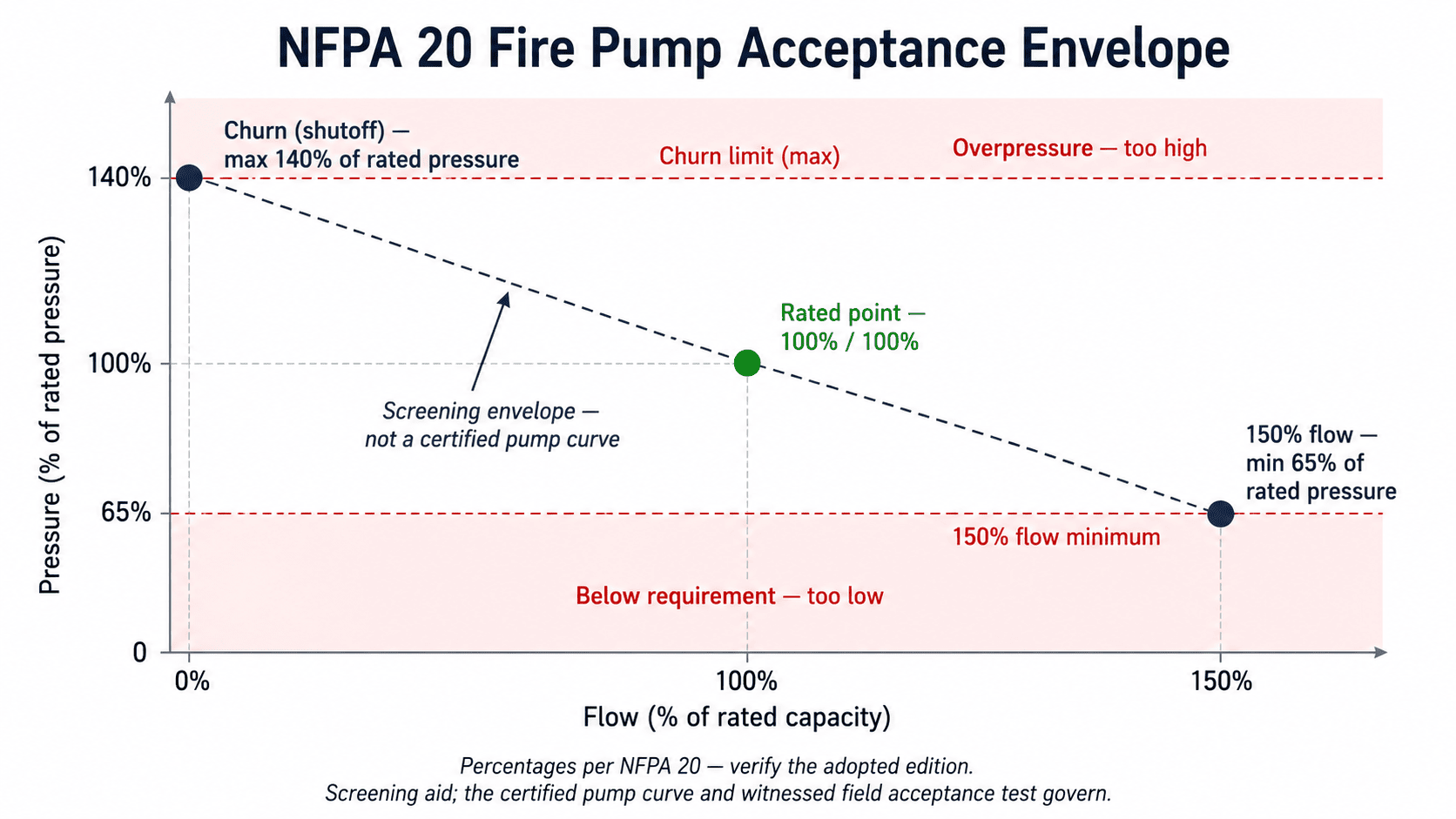
Fire Pump Acceptance Envelope
The acceptance envelope is the region on the pressure-vs-flow graph that a compliant fire pump curve must occupy. It is bounded by the three NFPA 20 criteria: a maximum churn at the left, a rated-point requirement at the center, and a minimum pressure floor at the right. A pump whose curve stays inside this envelope satisfies the NFPA 20 performance requirements.
The envelope is defined from a single rated-point input: max churn = rated pressure × 1.40, rated-point requirement = rated pressure at rated flow, overload flow = rated flow × 1.50, minimum pressure at overload = rated pressure × 0.65. Every other point on the curve between churn and 150% flow is implicitly constrained by the overall shape requirement, though NFPA 20 audits only those three points.
One important note: the envelope does not require the pump to produce exactly 140% at churn or exactly 65% at 150% flow. Those are the ceiling and the floor. A real pump's curve sits somewhere inside the envelope, and the job of the acceptance check is to confirm it does not violate either boundary. The manufacturer's certified pump curve, endorsed by UL or FM, defines the actual curve shape.
Churn Pressure vs Rated Pressure vs 150% Flow
Each of the three flow points on a fire pump curve has a different role and a different hazard direction.
Churn pressure is the pump's pressure at zero flow — the highest point on the curve. The hazard at churn is overpressure: too high a churn pressure overstresses piping and components and can cause the pressure-relief valve to open. NFPA 20 sets a ceiling of 140% of rated pressure. A pump that exceeds this limit in the field test fails the churn criterion.
The rated point establishes the pump's stated capacity. The pump must produce its full rated pressure at rated flow. Failing the rated point means the pump is not delivering what the system was designed around — and this failure is easy to miss when field teams check only churn and the 150% point. The 150% flow point is the overload check: at 1.5 times rated flow, the pressure must still reach at least 65% of rated. If the curve drops below the floor, the pump cannot sustain pressure during a surge demand.
Net Pump Pressure vs Discharge Pressure
Net pump pressure — also called differential pressure or net pump head — is the pressure the pump adds across itself, measured as the difference between discharge and suction. It is the value that should be entered for all three curve points. NFPA 20 defines the acceptance criteria in terms of net pump pressure, not raw discharge gauge pressure.
Raw discharge gauge pressure is not the same as net pump pressure when the pump has suction pressure. If suction at rated flow is 30 psi and the discharge gauge reads 130 psi, net pump pressure is 100 psi, not 130 psi. Using the raw 130 psi overstates the pump's contribution and can make a pump that fails the rated-point criterion appear to pass by 30%.
The error also applies to churn. At churn with some suction pressure, raw discharge is higher than net churn. A pump whose raw churn gauge pressure appears to exceed the 140% ceiling may actually be within limits once suction is subtracted — and conversely, a pump that looks marginal may be clearly within limits. Always subtract suction pressure before entering any pressure into a curve check.
Fire Pump Curve Check vs Field Acceptance Test
A curve check — whether done in this calculator or on paper — is a review of the pump's curve data against the NFPA 20 acceptance criteria. It is appropriate for design review, submittal checking, and pre-test screening. It is not a field acceptance test and does not count as acceptance under NFPA 20.
The NFPA 20 field acceptance test is a witnessed performance test of the installed pump. It flows the pump at churn, rated flow, and 150% flow with calibrated instrumentation — flow meters, gauges, and a data recorder — under the authority having jurisdiction. The witnessed test data, not any calculation or paper check, is the record that certifies the pump meets NFPA 20 requirements for that installation.
The difference matters practically. A submittal check using published curve data and this tool can screen a pump before the order is placed, catch obvious non-compliance before the pump ships, and flag the net-pressure vs discharge-pressure issue before the test. But it cannot substitute for flowing the actual installed pump. If the as-installed pump does not match the published curve — due to impeller wear, piping losses, or measurement error — the test result governs, not the paper check.
Key Facts
- A fire pump curve is judged at three points: churn at no flow, the rated point at 100% flow, and the overload point at 150% of rated flow.
- NFPA 20 caps churn pressure at 140% of rated pressure so the system is not overpressured at shutoff.
- NFPA 20 requires at least 65% of rated pressure at 150% of rated flow so the pump can meet a surge in demand.
- These percentages are limits, not target values. A real pump curve sits inside the envelope; assuming a pump produces exactly 140% or 65% is a common selection error.
- The curve uses net pump pressure — the pressure the pump adds across itself — not raw discharge gauge pressure.
- Listed fire pumps carry standard rated capacities, commonly 250, 500, 750, and 1,000 gpm among others; a non-standard rating should be confirmed against the pump's listing.
- The witnessed NFPA 20 field acceptance test flows the pump at churn, rated, and 150% with calibrated instruments; it is the verification that actually counts.
- A pump can meet the NFPA 20 curve envelope and still be wrong for a specific sprinkler or standpipe demand, which depends on the hydraulic calculation and the water supply.
Applications
- Building the NFPA 20 acceptance envelope from a pump's rated point during design review.
- Checking measured churn, rated, and 150%-flow pressures from a witnessed test against NFPA 20 criteria.
- Reviewing a fire pump submittal before sending it for approval.
- Screening a proposed pump's published curve points before accepting a submittal.
- Confirming that a churn pressure will not overpressure the downstream piping and components.
- Checking whether a measured rated-flow pressure actually reaches the pump's rated pressure, not just the churn and overload points.
- Catching a swapped or mis-entered curve point, or a raw discharge reading used in place of net pump pressure.
Example Calculation
Example 1 — Define the Envelope
A fire pump is rated at 1,000 gpm and 100 psi.
Acceptance envelope:
- Maximum churn: 100 × 1.40 = 140 psi
- Rated requirement: 100 psi at 1,000 gpm
- Overload flow: 1,000 × 1.50 = 1,500 gpm
- Minimum at overload: 100 × 0.65 = 65 psi
An acceptable curve has a churn no higher than 140 psi, makes 100 psi at 1,000 gpm, and holds at least 65 psi at 1,500 gpm.
Example 2 — Check a Measured Curve
The same pump is tested. Witnessed net pressures: 130 psi at churn, 102 psi at rated flow, 70 psi at 1,500 gpm.
- Churn: 130 / 100 = 1.30 ≤ 1.40 — Pass (margin 10 psi below ceiling)
- Rated: 102 / 100 = 1.02 ≥ 1.00 — Pass (margin 2 psi above requirement)
- Overload: 70 / 100 = 0.70 ≥ 0.65 — Pass (margin 5 psi above floor)
All three points pass — badge: MEETS SELECTED CRITERIA.
Example 3 — Raw Discharge Mistake
The rated-flow pressure is recorded as 120 psi from the discharge gauge. Suction pressure at that moment is 30 psi. Net pump pressure = 120 − 30 = 90 psi, a ratio of 0.90 — below 1.00. The pump fails the rated point. The raw discharge reading appeared healthy, but the pump is not making its rated pressure.
Example 4 — Rated-Point Failure Hidden by the Other Two
A pump rated at 1,000 gpm and 100 psi is tested: 130 psi churn (1.30 ✓), 95 psi at rated flow (0.95 ✗), 70 psi at 1,500 gpm (0.70 ✓). Churn and overload pass, but the rated point fails. Badge: DOES NOT MEET — RATED POINT. A check of only two points would have missed this.
Standards & References
- NFPA 20, Standard for the Installation of Stationary Pumps for Fire Protection — governing standard for the churn, rated, and overload criteria and the field acceptance test.
- NFPA 25, Standard for the Inspection, Testing, and Maintenance of Water-Based Fire Protection Systems — annual fire-pump flow test procedure.
- UL and FM Approvals listings — UL 448 and FM Class 1319 for listed centrifugal fire pumps; the manufacturer's certified pump curve is the governing performance document.
- Authority Having Jurisdiction (AHJ) — use the NFPA 20 edition adopted and enforced by the AHJ. This tool is a screening aid and does not replace the certified curve or the witnessed field acceptance test.
Limitations
- This is a screening and curve-verification aid, not a stamped design and not a field acceptance test of record. The certified pump curve and the witnessed NFPA 20 field acceptance test govern.
- The acceptance percentages are NFPA 20 values held in a screening profile and must be verified against the adopted edition and the pump listing.
- It works in net pump pressure / total head and does not derive net pressure from suction and discharge readings. The total discharge pressure including suction, which governs the system pressure rating at churn, is a separate check.
- It does not calculate flow from pitot readings, hose monsters, test headers, or flow meters, and does not correct readings for gauge elevation or velocity head.
- It does not validate the full certified manufacturer curve, and does not evaluate the fire protection system demand, so a pump that meets the curve shape may still not satisfy a specific system.
- It does not evaluate the water supply or suction conditions, and does not assess NPSH, cavitation, suction lift, submergence, or vortexing.
- It does not evaluate the driver horsepower, motor current, voltage, diesel engine data, controller operation, or automatic start sequence, and does not correct measured points to rated pump speed.
- It does not size pressure-relief valves or decide whether one is required, and does not replace the NFPA 25 annual flow test or the NFPA 20 field acceptance test.
Common Mistakes to Avoid
- Treating 140% and 65% as the pump's output instead of limits. They are the ceiling at churn and the floor at 150% flow; a real curve sits inside the envelope.
- Comparing raw discharge gauge pressure to the rated pressure. The curve uses net pump pressure; a discharge gauge also reads the suction pressure, so a raw reading must have the suction removed first.
- Checking only churn and 150% flow. The rated point matters: a pump can pass churn and overload and still fail to make its rated pressure at rated flow.
- Assuming the screening percentages match the adopted edition without verifying. The exact values depend on the NFPA 20 edition the AHJ enforces.
- Assuming a curve pass means the system demand is met. A pump can meet the NFPA 20 curve envelope and still be wrong for a specific sprinkler or standpipe demand.
- Comparing points taken at a different speed without correction. A curve is valid at a stated pump speed; readings at a different speed should be corrected before comparison.
- Treating the screening result as acceptance. The witnessed field acceptance test, with flows at churn, rated, and 150%, is the verification that counts.
Frequently Asked Questions
What does a fire pump performance curve show?
What is churn pressure on a fire pump?
Why must a fire pump deliver 65% of rated pressure at 150% flow?
Are 140% and 65% the values a fire pump produces?
What happens if the rated-flow point fails?
Is churn pressure the same as discharge pressure?
Does this calculator replace the fire pump acceptance test?
Can a fire pump pass the curve check but still be undersized?
Frequently Used Together
Engineers often use these calculators in combination for complete project workflows:
Related Calculators
Explore similar calculators that might be useful for your project:
Plumbing Quick Reference — Keep It On Your Phone On Site
A 10-page field reference for catching pressure, velocity, slope, and pump-sizing mistakes before you order pipe, close a wall, or add a booster.
- Velocity limits, fixture pressure minimums, drain slope, and the 80 psi ceiling in one table
- Worked examples that show why a single pressure number gives four different answers
- Keep it on your phone, or print the two field-check pages
Free PDF. Calculators stay free. Unsubscribe anytime.
Calculate
Define mode returns the three acceptance limits from the rated point. Check mode evaluates measured churn, rated-flow, and 150%-flow pressures against those limits.
Choose whether pressures are entered as gauge pressure (psi/bar) or as pump head (ft/m). The criteria ratios are unit-independent; only the display changes.
The pump's rated capacity (100% point). NFPA 20 lists standard rated capacities; a non-standard value is flagged, not blocked.
Net pump pressure / total head at rated flow — not raw discharge gauge pressure. This is the nameplate pressure the pump adds across itself at the 100% flow point.
The acceptance percentages used for all three points. Verify against the NFPA 20 edition adopted by the authority having jurisdiction. v1 ships one profile.
Nameplate pump speed. If the test speed differs from the rated speed, a soft check fires. This tool does not correct points to rated speed.
Actual pump speed during the test. Enter if it differs from rated speed to trigger the speed-correction note.