Equivalent Length of Pipe Fittings Calculator — L/D Ratios and Total Developed Run
On this page
Calculate
This selector governs every field, label, result and export here and takes priority over the site header switch. Switching converts what you entered rather than reinterpreting it, so 100 ft becomes 30.48 m and returns to exactly 100. Nominal pipe sizes stay in inches in both systems with the DN figure alongside, because that is how pipe and fittings are ordered.
The Pipe
The material standard sets two separate things: the bore the equivalent length is proportional to, and the friction factor it is inversely proportional to. There is no broad copper or plastic option, because a Type L bore and a Type K bore are different numbers and a family name does not choose between them.
One size per calculation. The nominal size selects the reference friction factor the L/D table was established at, and on a named standard it selects the bore as well. Copper Type L is modelled to 8 in and CPVC CTS to 2 in; a size outside a standard is named rather than borrowed from a neighbouring one.
The measured centreline length of straight pipe on one hydraulic path at this size and material, with no allowance for fittings added. Enter 0 where the run is a fitting assembly with no straight pipe between its ends, which is a real case and the one a percentage allowance cannot describe.
The Fittings on This Run
Count the fittings on one hydraulic path, not every fitting in the building. L/D 30. A standard radius elbow is the short pattern; if the drawing says long radius, use the field below instead.
L/D 16, which is a little over half the standard pattern. The difference between the two elbow rows is the largest easy saving on a fitting-heavy run, and it costs nothing but space.
L/D 16. Two 45 degree elbows are not one 90 degree elbow in this table: they come to 32 against 30, so a swept offset is marginally worse than a single standard bend rather than better.
L/D 20. Count a tee here where the flow you are calculating passes straight through it. A tee is two different fittings and the direction is a property of the path, not of the fitting, so the same tee is counted in the run field on one path and the branch field on another.
L/D 60, three times the run figure. Count a tee here where the flow you are calculating turns into or out of the branch. This is the single most common undercount on a fitting schedule.
L/D 8, the smallest figure in the table. A gate valve fully open is close to a piece of pipe. Fully open is the only condition published, and a throttled gate valve is not a smaller number from this row.
L/D 340, the largest figure in the table and forty two times a gate valve. One 2 in globe valve is 58.6 ft of 2 in steel pipe on its own. If a run is losing more head than it should, this is the first row to look at.
L/D 100. A swing check valve needs enough flow to hold its disc fully open, and the published figure assumes it is. Published guidance warns that generic data for check valves can vary from the real component by minus 50 to plus 100 percent.
Size banded rather than a single figure: L/D 45 from 2 to 8 in, 35 from 10 to 14 in and 25 from 16 to 24 in. A table that publishes one butterfly number has flattened a banded row. Below 2 in the 45 figure is carried down and the result says it was extrapolated.
L/D 180 for a clean strainer, and this row is not from Crane, which publishes no strainer at all. It carries its own source on every result. A fouling strainer changes the geometry rather than scaling the coefficient, so it needs manufacturer pressure drop data instead.
Overriding the Table
Leave blank to use the bore from the material standard and nominal size. Required where the material is Other. Enter the internal diameter, never the nominal size and never the outside diameter: the equivalent length is directly proportional to this figure.
The friction factor of the pipe this fitting sits in. Leave blank to use the figure for the material standard you chose. Required where the material is Other. Darcy factors for water in commercial pipe sit roughly between 0.013 and 0.040; a figure near 0.005 is almost certainly Fanning.
Answer this whenever you enter a friction factor. Darcy and Fanning differ by a factor of four for the same condition and neither figure carries a label. A Fanning value used where a Darcy value belongs returns an equivalent length four times too long, and no arithmetic here would catch it, so an unknown basis stops the calculation rather than guessing.
Leave blank to use the Crane fully turbulent factor for clean commercial steel at this size, which is the basis the published L/D ratios were established at. Enter a figure only where you are using L/D values from a source that states a different basis. This is not a property of your pipe.
Manufacturer Data for One Fitting
Optional, and it replaces the generic table row for that one fitting type only. Name the fitting before entering a figure: a value with no fitting named is not applied, and the result says so rather than reporting a pass.
The cleanest of the three transfers, and the one used first where more than one is entered. A K value is converted to a length at this bore and this pipe friction factor exactly as a table value would be.
Used where no K value is entered. It goes through the same two step conversion as a table row, so it picks up the reference and pipe friction factors above.
Used only where neither a K value nor an L/D ratio is available, because a published length already has a friction factor assumption baked into it and is valid only for the condition it was quoted at. It is added directly, per fitting, with no conversion.
Matters most for a published equivalent length, which does not transfer between sizes or materials. Where the figure was quoted at a different condition, or at a condition nobody recorded, the result flags it rather than absorbing it silently.
Additional Allowance
One L/D figure covering everything the ten counted types do not: unions, couplings, equipment connections, a balancing valve, a flow meter. It is converted at the same bore and factors as a table row, and it is reported separately, because that part of the total is yours rather than a published table's.
Required as soon as an allowance is entered. An unlabelled L/D addition cannot be attributed to anything six months later, and it is excluded from any claim that the total came from a published table.
Overview
An equivalent length answers one question: how many feet of this particular pipe would lose what this fitting loses.
That wording is the whole method, and it contains the thing most tables get wrong. The answer depends on the fitting and on the pipe it sits in, so the same 2 inch standard elbow is 5.2 feet in Schedule 40 steel, 5.9 feet in Type L copper and 7.0 feet in Schedule 40 PVC. Smoother pipe loses less per foot, so it takes more feet of it to lose what the elbow loses.
Getting there takes two steps and two friction factors that are never the same variable. The published L/D ratio becomes a resistance coefficient at the factor its table was measured at, and that coefficient becomes a length at the factor your pipe actually has.
The number this page produces is an input rather than an answer. It replaces the percentage allowance a friction loss, pump head or recirculation calculation applies when nobody has drawn the route yet.
What to Look at First
Read the ratio of the two friction factors first, then the fitting share of the total.
The ratio is the material sensitivity and it is the same on every fitting on the run, so one glance tells you how far the answer has moved from the steel table the L/D ratios were measured in. A ratio of 1 to 1 means you are in commercial steel and the published figures apply directly.
The fitting share tells you what kind of run this is. Below about 20 percent the pipe is carrying the answer and a percentage allowance would have been close enough; above 50 percent the fitting count is carrying it, and the design response to that is different from the response to a long pipe run.
How to Use This Calculator
Choose the pipe material with its standard, then the nominal size. Both are needed before anything is computed: the standard and the size together select the bore, and the size selects the reference friction factor the L/D table was established at.
Break the system into runs first. One calculation covers one size in one material standard on one hydraulic path. Where the size changes, both the bore and the friction factor change with it, so lengths from either side of a transition cannot be added.
Enter the measured straight pipe length on that run, with no allowance for fittings added. Enter 0 where the assembly has no straight pipe between its ends.
Count the fittings on that one path. Count a tee in the run field where the flow passes straight through and in the branch field where it turns, because the two are different fittings at L/D 20 and 60 and the direction belongs to the path rather than to the tee.
Leave the override block blank unless you have a reason. The bore and the pipe friction factor come from the standard you chose. Fill them in where you have measured the pipe, where the material is Other, or where you want to see what a different factor does.
State the basis whenever you enter a friction factor. Darcy and Fanning differ by a factor of four, the arithmetic runs either way, and an unstated basis stops the calculation rather than guessing.
Add manufacturer data for one fitting where you have it, naming the fitting first. A K value transfers most cleanly, then an L/D ratio, then a published length, and the page uses them in that order where more than one is entered.
Use the additional allowance for anything the ten counted types do not cover, as a single L/D figure, and say what it covers. That part of the total is reported separately because it is yours rather than a published table's.
Carry the total developed length into the friction loss, pump head or recirculation calculation for that run, and carry the band with it. The fitting portion has a 25 percent tolerance either way and the straight length carries none of it.
Inputs & Outputs
Inputs
Outputs
Equivalent Length Formula
The conversion is two steps, and the two friction factors in it are different quantities.
Step one, the ratio becomes a resistance coefficient at the basis its table was measured at
K_ref = (L/D) * f_ref
Step two, the coefficient becomes a length in the pipe you actually have
Le = K_ref * d / (12 * f_pipe)
With Le in feet and the bore d in inches. Combined into one line
Le = (L/D) * (f_ref / f_pipe) * d / 12
The ratio f_ref / f_pipe is the entire material sensitivity. It is the same on every fitting on the run, because it does not depend on the fitting.
From a manufacturer K value, which skips step one
Le = K * d / (12 * f_pipe)
The total developed length
L_total = L_straight + sum(n_i * Le_i)
Where n_i is the count of each fitting type on one hydraulic path.
The band on the total, at the published 25 percent tolerance for standard fittings
L_low  = L_straight + 0.75 * L_fittings
L_high = L_straight + 1.25 * L_fittings
The straight length carries none of the uncertainty, so the band is on the fitting portion alone.
Against a percentage allowance
L_allowance = 0.5 * L_straight
What a downstream calculation would have added for fittings with the route undrawn, at the bottom of the usual 50 to 100 percent range.
What cancellation does
f_ref = f_pipe -> Le = (L/D) * d / 12
Set the two factors equal and both vanish. Every material then returns the same figure, and there is nothing in the arithmetic to signal that a different method is now running.
Unit conversions: 1 foot equals 0.3048 metres and 1 inch equals 25.4 millimetres, both exact. The L/D ratio, K and the friction factor are dimensionless.
Equivalent Length of Pipe Fittings
An equivalent length is the length of straight pipe that would produce the same pressure loss as a fitting. It exists so that a route made of pipe and fittings can be reduced to a single length, which a friction loss calculation can then take as one input.
Read the definition again with the emphasis in the right place: the same pressure loss as a fitting, in that pipe. The fitting's own loss is a fixed thing at a given velocity. What changes between materials is how many feet of pipe it takes to match it, because smooth pipe loses less per foot. So a 2 inch standard 90 degree elbow is 5.2 feet in Schedule 40 steel, 5.9 feet in Type L copper and 7.0 feet in Schedule 40 PVC, and none of those numbers is a correction of the others.
That is why any table publishing one equivalent length per fitting has assumed a pipe, usually clean commercial steel, and usually without saying so. Copy such a table into a plastic system and every figure is roughly 25 percent low. The error is systematic rather than random, so it does not average out across a long fitting schedule; it accumulates.
The method's real virtue is that it needs no flow rate. You can count fittings and reduce a route to a length before anyone knows what the flow will be, which is exactly the order design work happens in. That same property is its limit, and it is discussed further down.
The L/D Ratio and What It Measures
The published data is not a length. It is a dimensionless ratio, written L/D or n, and it says how many pipe diameters of that pipe the fitting is worth.
A standard 90 degree elbow at L/D 30 is worth 30 diameters of its own pipe. In 2 inch pipe with a 2.067 inch bore that is 62 inches, or 5.17 feet. In 6 inch pipe with a 6.065 inch bore the same L/D 30 is 182 inches, or 15.2 feet. The ratio is constant; the length is not.
Working in ratios rather than lengths is what makes the data portable, and it is the reason published guidance calls the L/D method largely self correcting for changes in fitting size. Scale the pipe and the fitting scales with it, so one number covers the whole size range for that fitting type.
Crane Technical Paper No. 410 expresses each fitting as K equals n times fT, where n is the fixed L/D equivalent and fT is the fully turbulent friction factor for clean commercial steel at that size. That is the form the ratios in this calculator are used in, and it is why the reference friction factor is a separate quantity from the pipe's own.
One consequence worth holding onto: because the ratios span a factor of forty, from a gate valve at 8 to a globe valve at 340, which fittings are on a run decides the answer far more than how many there are. Twenty elbows come to L/D 600. A single globe valve and two swing check valves come to 540. The second list is three components.
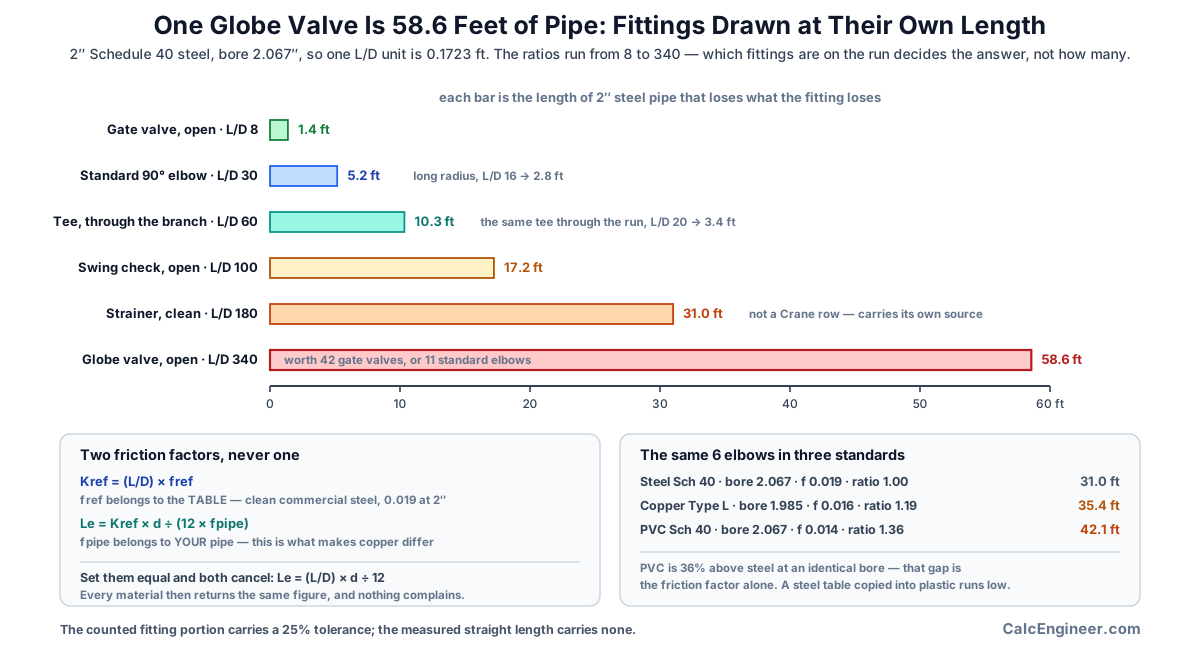
Two Friction Factors, Never One
The conversion runs in two steps, and the two friction factors in it are different quantities that happen to share a symbol.
Step one turns the ratio into a resistance coefficient at the basis the ratio was measured at:
K_ref = (L/D) * f_ref
Step two turns that coefficient into a length in the pipe you actually have:
Le = K_ref * d / (12 * f_pipe)
The reference factor f_ref is a property of the table. It is the fully turbulent factor for clean commercial steel at that nominal size, from Crane Appendix A-26: 0.027 at half inch, 0.023 at one inch, 0.019 at two inch, 0.017 at four inch, 0.015 at six inch, 0.014 at eight to ten inch and 0.013 at twelve to sixteen inch. It does not describe your pipe and it does not change when you change material.
The pipe factor f_pipe is a property of your pipe. It is what makes copper different from steel.
Substitute the first equation into the second with both factors set to the same variable and they cancel:
Le = (L/D) * d / 12
That is a different method with a different meaning. It returns the same figure for every material, the material sensitivity vanishes, and nothing in the arithmetic complains, because the result is still a plausible number in the right units. It is the single most common way an equivalent length table gets built wrong, and it is why this calculator reports both factors and the ratio between them on every result.
The ratio itself is the whole material sensitivity, and it is identical on every fitting in the table because it does not depend on the fitting at all. In this calculator steel Schedule 40 gives a ratio of 1, Type L copper 1.188 and smooth thermoplastic 1.357. Multiply any steel equivalent length by one of those and you have the figure for that material at the same bore.
Both factors in that conversion are Darcy factors, and the difference between a Darcy figure and a Fanning one is the section that follows.
Darcy Versus Fanning Friction Factor
Every friction factor on this page is a Darcy factor, because Crane works in Darcy. The Fanning factor is one quarter of the Darcy factor for the same condition, neither figure carries a label, and a Fanning value used where a Darcy value belongs returns an equivalent length four times too long. Two inch commercial steel in fully turbulent flow is about 0.019 Darcy and about 0.00475 Fanning, and both numbers describe the same pipe in the same flow.
The size of the number is a first check on which one you are holding. Darcy factors for water in commercial pipe sit roughly between 0.013 and 0.040, so a figure near 0.005 is almost certainly Fanning.
That check catches the extreme case and misses the ordinary one. Example 6 works it through. A Fanning 0.00475 read as Darcy falls outside any plausible turbulent range and the page stops, but a Fanning 0.010, the sort of figure a rougher or a smaller line produces, is plausible read either way. Named as Fanning it becomes a Darcy 0.040 and a two inch standard elbow returns 2.5 ft; named as Darcy it stays at 0.010 and the same elbow returns 9.8 ft. Both totals look equally like totals.
That is why an unstated basis stops the calculation here rather than being inferred from the size of the number. It is also the one error on this page that no internal check can catch: a wrong bore or a tee counted in the wrong direction returns a figure that is slightly short, while a Fanning value returns a figure four times too long that looks exactly like a correct one. If you enter a friction factor, the page asks which basis it is on and stops when the answer is unknown.
Nominal Size Versus Actual Bore
The equivalent length is directly proportional to the bore, and the bore is not the nominal size.
Nominal pipe size is a trade designation. It has not been a dimension since the nineteenth century, when it was roughly the internal diameter of the wrought iron pipe of the day. Schedule 40 steel at half inch has a 0.622 inch bore. At two inch it is 2.067. At twelve inch it is 11.938.
So the error from using the nominal figure is not a constant. At half inch the nominal figure is 19.6 percent below the bore and every equivalent length comes out that much short. At two inch it is 3.2 percent short. At twelve inch the nominal figure is half a percent above the bore, so the error changes sign. Small pipe is where it matters, and small pipe is where fitting-dominated runs live.
The bore also depends on the schedule and the material standard, not only on the size. Two inch Schedule 40 PVC has the same 2.067 inch bore as Schedule 40 steel, because the schedule sets the wall thickness; Schedule 80 PVC at the same nominal size has a 1.939 inch bore, a 6 percent reduction, and its equivalent lengths fall by the same 6 percent. Copper Type L at two inch is 1.985, and CPVC in CTS sizes at nominal two inch is 1.739, which is 16 percent below the steel figure. Those are different products with the same number written on them.
This is also the reason the material options here are named by standard rather than by family. There is no copper option, because Type K, Type L and Type M have three different walls; there is no plastic option, because Schedule 40, Schedule 80 and CPVC CTS have three different bores. A family name cannot select a dimension.
The Fitting Table and Where It Comes From
The L/D ratios used here are the Crane Technical Paper No. 410 values, which is the reference nearly every published equivalent length table traces back to.
The ratios: standard 90 degree elbow 30, long radius 90 degree elbow 16, 45 degree elbow 16, tee through the run 20, tee through the branch 60, gate valve fully open 8, globe valve fully open 340, swing check valve fully open 100. The butterfly valve is size banded rather than a single figure, at 45 for 2 to 8 inch, 35 for 10 to 14 inch and 25 for 16 to 24 inch, and a reproduction that publishes one butterfly number has flattened that row.
Two things about this data deserve stating plainly. First, the measurements are pre-1976, and current editions of Crane TP-410 publish resistance coefficients rather than equivalent lengths. The L/D ratios in wide circulation are the older presentation. Second, no plumbing or mechanical code publishes an equivalent length table, so this is published engineering data rather than a code requirement, and an authority having jurisdiction has nothing to say about it.
The strainer is a deliberate exception in this calculator and it is labelled as one on every result. Crane publishes no strainer at all. The clean strainer figure of 180 used here comes from a separate published equivalent length table and its worked DN80 example. A GPSA figure of 250 is also in circulation. Both sit inside the spread that published guidance warns about for proprietary items: actual flow data for items like strainers and check valves can vary from generic data by minus 50 to plus 100 percent.
Every figure in the table is a fully open or clean condition, and that is a boundary rather than a caveat. A partially open valve is not a smaller number from the same row. It is a coefficient the generic table does not carry, because closing a valve changes the geometry of the flow path rather than scaling its resistance, and the only honest source for it is manufacturer pressure drop data at that position. The same applies to a fouled strainer.
No ball valve field is offered. Crane does publish a full bore value of 3, but the reduced port case depends on a diameter ratio, which is a geometry change this method does not model, and a full port only field would be filled in for reduced port valves by whoever met it.
A Tee Is Two Different Fittings
The published ratio for a tee is 20 through the run and 60 through the branch. The branch is three times the run, and on a real system both paths exist at once.
What that means in practice is that the direction is a property of the path you are calculating, not of the fitting on the drawing. The same physical tee is counted as a run fitting when you follow the main and as a branch fitting when you follow the takeoff. Counting every tee once, in one direction, is not a simplification; it is an answer to a different question.
This calculator therefore takes two separate counts rather than one count and a direction selector. A single count with a dropdown reads as though a tee has a direction, and it makes the mixed case, which is the normal case, impossible to enter.
The undercount runs one way. A branch tee entered as a run tee loses 40 diameters, which is 6.9 feet in 2 inch steel per fitting. Four of them is 27.6 feet of pipe that is not in the calculation, on a run that might only be 100 feet long.
Counted Length Versus the Percentage Allowance
Design guidance that has no route to work from adds a percentage. The common allowance is 50 to 100 percent of the measured straight length for fittings, and it exists because at concept stage nobody has drawn the pipework yet.
A counted equivalent length replaces that allowance, and the useful output is not just the number but which side of the allowance the run falls on. That is what a percentage cannot tell you, because it scales with pipe length and the fitting content does not.
Take a 100 foot run of 2 inch steel with six standard elbows, two run tees, one branch tee, two gate valves and one swing check valve. The fittings come to 68.2 feet. A 50 percent allowance would have added 50 feet, understating them by 18.2 feet, or 27 percent of the fitting total.
Now take the same 100 feet of pipe with two gate valves and nothing else. The fittings come to 2.8 feet and the 50 percent allowance would have added 50, overstating them by a factor of eighteen.
Now take a plant room manifold, 12 feet of 2 inch steel carrying a strainer, a globe valve, a swing check valve and eight elbows. The fittings come to 148.1 feet against 12 feet of pipe. The allowance would have added 6.
Three runs, three answers, and the pipe length predicts none of them. What decides it is what is in the run, which is precisely the information a percentage allowance does not have.
The Uncertainty Band on the Method
A counted figure is not a precise figure, and this page reports the fitting portion as a range rather than a single number.
Published guidance on pressure drop through fittings puts the achievable accuracy at 10 percent at the very best and 25 to 30 percent as a realistic estimate, and recommends assuming a 25 percent tolerance in calculations because standard elbows and tees vary from manufacturer to manufacturer. That is the band this calculator applies.
The band goes on the fitting portion only. The measured straight length carries none of it, so a run that is mostly pipe has a narrow band on its total and a run that is mostly fittings has a wide one. That is a genuinely useful signal about how much weight the total will bear.
It also sets the precision. A method carrying 25 to 30 percent uncertainty cannot support two decimal places, so every figure here is shown to one and the decision figure is a range. A total quoted as 168.21 feet claims a precision that nothing behind it supports.
What the band does not cover is a wrong count or a wrong direction on a tee. Those are errors rather than uncertainty, and no tolerance absorbs them.
Where the L/D Method Stops Working
The method takes no flow rate. That is what lets you use it before the flow is known, and it is also the boundary.
The published L/D values are fully turbulent measurements. Below fully turbulent flow the friction factor of the pipe rises, and since the equivalent length is inversely proportional to it, the equivalent length falls: by roughly a factor of two between a Reynolds number of 4,000 and fully developed turbulent flow in 2 inch steel. So one equivalent length carried unchanged across several flow scenarios is the most likely way to misuse the result. At low flow it is conservative; the number is too long rather than too short.
Published guidance is direct about the standing of the method: it describes the L/D approach as very suitable for preliminary or hand calculations where ultimate accuracy is not the main goal, and names Darby's 3-K method as the best presently available for accommodating changing pipe sizes. The 2K and 3K methods take a Reynolds number, which is exactly the input this method does without.
Several things are geometry changes rather than coefficient changes, and the generic table does not cover any of them: reducing fittings, sudden enlargements and contractions, partially open valves, reduced port ball valves, and insert fitting systems that narrow the bore at every joint. Each needs its own treatment.
And the calculation covers one size in one material standard. At a size transition both the bore and the friction factor change, so adding developed lengths across it is wrong. Break the system into runs where size, material and fitting set stay constant, compute each separately, and feed each length into the friction calculation for that run. A quantity of identical parallel runs is not a multiplier either, because parallel paths do not lengthen a hydraulic path.
What Is Total Developed Length
Total developed length is the measured straight pipe on a run plus the equivalent lengths of everything in it. It is the number a friction loss calculation wants.
The order matters when you use it. Developed length is a length, not a pressure drop. The loss itself comes from a pipe flow calculation, Darcy-Weisbach or Hazen-Williams, that takes this length together with a flow rate and a diameter. This page deliberately stops short of that, because the moment a flow rate enters the picture the fully turbulent assumption behind the L/D ratios has to be examined, and that belongs in the calculation that owns the flow.
The most common consumer of a developed length in building services is a pump head calculation. A hot water recirculation loop is the clearest case: the loop head is dominated by friction rather than by static lift, the route is fitting-dense, and the usual practice of applying a percentage allowance for fittings is exactly the assumption a counted length replaces.
Carry the band with the number. A developed length of 168.2 feet on a fitting-heavy run genuinely sits between 151.2 and 185.3, and a pump selected at the bottom of that range on a run that turns out to be at the top will not make its design flow. Selecting against the upper figure and checking the lower one is the honest way to use it.
One last framing. This page produces an input, not a conclusion. It judges nothing, it passes nothing and it fails nothing. The completed state says what it is: the inputs were complete and the arithmetic ran.
Key Facts
- An equivalent length is the length of straight pipe that would produce the same pressure loss as the fitting, in that pipe. It is a property of the fitting and the pipe together, not of the fitting alone.
- Crane Technical Paper No. 410 expresses each fitting as K equals n times fT, where n is the fixed L/D equivalent for the fitting type and fT is the fully turbulent friction factor for clean commercial steel at that size.
- The two step conversion is K_ref = (L/D) * f_ref, then Le = K_ref * d / (12 * f_pipe) with the bore d in inches. Using one friction factor for both cancels them and leaves Le = (L/D) * d / 12, which returns the same answer for every material.
- Crane L/D ratios: standard 90 degree elbow 30, long radius 90 degree elbow 16, 45 degree elbow 16, tee through the run 20, tee through the branch 60, gate valve 8, globe valve 340, swing check valve 100, all fully open.
- The butterfly valve is banded by size rather than published as one figure: 45 for 2 to 8 inch, 35 for 10 to 14 inch and 25 for 16 to 24 inch.
- Crane fully turbulent friction factors for clean commercial steel: 0.027 at half inch, 0.023 at one inch, 0.019 at two inch, 0.017 at four inch, 0.015 at six inch, 0.014 at eight to ten inch and 0.013 at twelve to sixteen inch.
- The published ratios span a factor of forty two, from a gate valve at 8 to a globe valve at 340. One 2 inch globe valve is 58.6 feet of 2 inch steel pipe; one 2 inch gate valve is 1.4 feet.
- A 2 inch standard 90 degree elbow is 5.2 feet in Schedule 40 steel, 5.9 feet in Type L copper and 7.0 feet in Schedule 40 PVC. The fitting loses the same amount in all three; the pipe does not.
- Nominal size is a trade designation, not a dimension. Half inch Schedule 40 steel has a 0.622 inch bore, 19.6 percent above the nominal figure, and 12 inch has an 11.938 inch bore, half a percent below it.
- Schedule 40 PVC and Schedule 40 steel share a bore at every size, because the schedule sets the wall. What differs is the friction factor, which is the other half of the conversion.
- Darcy and Fanning friction factors differ by a factor of four for the same condition. Two inch commercial steel in fully turbulent flow is about 0.019 Darcy and 0.00475 Fanning, and neither number carries a label.
- Published guidance puts the accuracy of fitting pressure drop data at 10 percent at the very best and 25 to 30 percent as a realistic estimate, and recommends assuming a 25 percent tolerance in calculations.
- Generic data for proprietary items such as strainers and check valves can vary from the real component by minus 50 to plus 100 percent, which is why a manufacturer figure beats a table row for those two.
- Crane TP-410 publishes no strainer. The clean strainer figure of 180 comes from a separate published equivalent length table, and a GPSA figure of 250 for Y strainers is also in circulation.
- Below fully turbulent flow the pipe friction factor rises and the equivalent length falls with it, by about a factor of two between a Reynolds number of 4,000 and fully developed flow in 2 inch steel.
- Design guidance with no drawn route adds 50 to 100 percent of the straight length for fittings. On a counted run that allowance can be out by a factor of eighteen in either direction, and pipe length does not predict which.
- Commercial steel has an absolute roughness of about 0.045 mm against 0.0015 mm for drawn tubing and smooth thermoplastic, thirty times less, which is where the material difference in the friction factor originates.
- No plumbing or mechanical code publishes an equivalent length table. The L/D ratios in circulation are pre-1976 Crane measurements, and current editions of TP-410 publish resistance coefficients instead.
Applications
- A plumbing designer reduces a hot water recirculation loop to a developed length before selecting the circulator, replacing the percentage allowance the pump sizing would otherwise apply.
- An engineer sizing a chilled water branch counts a strainer, a balancing valve and eight elbows and finds the fittings exceed the pipe they are made of, which changes the plant room layout rather than the pipe size.
- A contractor comparing a routed and a direct pipe run works out what the extra elbows cost in developed length before deciding whether the shorter route through the ceiling is worth it.
- A designer converting a specification from steel to CPVC checks how far the equivalent lengths move when the bore drops 16 percent and the friction factor drops with it.
- A commissioning engineer investigating a loop that will not reach design flow counts the fittings on the index run and finds a globe valve that was drawn as a gate valve.
- A service engineer replacing standard elbows with long radius elbows on a fitting-dense riser quantifies the saving before the pipework is ordered.
- An estimator sanity checks a pump duty that was set from a 100 percent fitting allowance against a counted figure on the actual route.
- A design reviewer checks whether a developed length quoted on a drawing was built from the actual bore or from the nominal size, which on small pipe is a 20 percent difference.
- A specifier with manufacturer K values for a proprietary valve substitutes them for the generic row on that one fitting and leaves the rest of the schedule on the published table.
Worked Examples
Example 1. A counted run against the allowance
Given: 100 ft of 2 in Schedule 40 steel, bore 2.067 in, reference and pipe friction factors both 0.019 so the ratio is 1. Fittings on the path: six standard 90 degree elbows, two run tees, one branch tee, two gate valves, one swing check valve.
One L/D unit in this pipe is 2.067 / 12, or 0.1723 ft.
Standard elbows: 6 at L/D 30 is 6 times 5.2, or 31.0 ft. Swing check: 1 at L/D 100 is 17.2 ft. Branch tee: 1 at L/D 60 is 10.3 ft. Run tees: 2 at L/D 20 is 6.9 ft. Gate valves: 2 at L/D 8 is 2.8 ft.
Fittings: 68.2 ft, between 51.2 and 85.3 at the 25 percent tolerance. Total developed length: 168.2 ft, between 151.2 and 185.3.
The fittings are 41 percent of the developed length and 68 percent of the straight length. A 50 percent allowance would have added 50 ft, understating the fittings by 18.2 ft.
In metric that is 30.5 m of pipe, 20.8 m of fittings and 51.3 m developed, between 46.1 and 56.5.
Example 2. The same fittings in three materials
Given: six standard 90 degree elbows at nominal 2 in, straight length ignored.
Steel Schedule 40, bore 2.067, pipe factor 0.019, ratio 1: 5.2 ft each, 31.0 ft total.
Copper Type L, bore 1.985, pipe factor 0.016, ratio 1.188: 5.9 ft each, 35.4 ft total.
PVC Schedule 40, bore 2.067, pipe factor 0.014, ratio 1.357: 7.0 ft each, 42.1 ft total.
The PVC figure is 36 percent above the steel one for identical fittings at an identical bore. Note that PVC Schedule 40 and steel Schedule 40 share that bore exactly, so the whole difference here is the friction factor. Copper is the other way round: it moves on both, a smaller bore pulling down and a smoother wall pushing up.
These are not three answers for one run. They show what the answer depends on.
Example 3. What one globe valve costs
Given: 2 in Schedule 40 steel.
Gate valve, L/D 8: 1.4 ft. Globe valve, L/D 340: 58.6 ft.
One globe valve is worth forty two gate valves, eleven standard elbows, or more straight pipe than most branch runs contain. If a run is losing more head than the drawing suggests it should, the valve schedule is the first place to look and the elbow count is close to the last.
Example 4. Nominal size instead of bore
Given: six standard 90 degree elbows in Schedule 40 steel, computed twice, once on the bore and once on the nominal figure.
At half inch: bore 0.622 gives 1.6 ft each; the nominal 0.5 gives 1.3. The nominal figure is 19.6 percent low.
At two inch: bore 2.067 gives 5.2 ft each; the nominal 2 gives 5.0. The nominal figure is 3.2 percent low.
At twelve inch: bore 11.938 gives 29.8 ft each; the nominal 12 gives 30.0. The nominal figure is now half a percent high.
The error shrinks with size and changes sign at the top of the range, which is why it survives so long unnoticed: on the large pipe people check, it is invisible.
Example 5. A fitting assembly with no straight pipe
Given: a plant room manifold, 12 ft of 2 in Schedule 40 steel carrying a clean strainer, a globe valve, a swing check valve and eight standard elbows.
Strainer at L/D 180: 31.0 ft. Globe valve at 340: 58.6 ft. Swing check at 100: 17.2 ft. Elbows, 8 at 30: 41.3 ft.
Fittings: 148.1 ft. Total developed length: 160.1 ft, of which the fittings are 93 percent. A 50 percent allowance would have added 6 ft.
This is the case a percentage allowance cannot describe at all, and it is not rare: it is what the inside of a plant room looks like. The design response is also different. There is no point resizing the pipe, and every argument here is about which components are in the assembly.
Example 6. The Fanning trap
Given: 2 in steel, and a friction factor taken from a source that publishes Fanning values.
At 0.00475, the Fanning figure for this pipe, naming the basis as Fanning multiplies it by four to give a Darcy 0.019, and a standard elbow returns 5.2 ft. Naming the same digits as Darcy is caught: 0.0047 is outside the plausible Darcy turbulent range of 0.008 to 0.1 and the page stops rather than computing.
The range check does not save you further up. At a Fanning 0.010, which is the sort of figure a rough or smaller line produces, both answers are inside the range. Named as Fanning it becomes a Darcy 0.040 and the elbow returns 2.5 ft. Named as Darcy it stays at 0.010 and the same elbow returns 9.8 ft, a factor of four apart with both totals looking equally like totals.
That is why the page refuses to compute when the basis of an entered factor is unknown. A plausibility band catches the extreme case and misses the ordinary one, which is exactly the pattern that makes an error survive.
Standards & References
- Crane Technical Paper No. 410, Flow of Fluids Through Valves, Fittings and Pipe The source of the L/D equivalents and of the fully turbulent friction factors in Appendix A-26. Crane expresses each valve and fitting as K equals n times fT, where n is the fixed L/D equivalent and fT is the fully turbulent factor for clean commercial steel at that size. Current editions publish resistance coefficients rather than equivalent lengths; the L/D presentation in wide circulation is the older one.
- SimuPipe K factor and L/D equivalent table The reproduction of the Crane TP-410 table the L/D ratios here were read from, including the size banded butterfly valve rows and the Appendix A-26 friction factor column.
- HydraulicCalc equivalent length reference The independent reproduction used to cross-check every ratio. It agrees with the SimuPipe table on every row the two have in common, which is what the stored values rest on.
- Katmar Software, pressure drop in pipe fittings and valves, equivalent length and resistance coefficient The review of the competing methods behind the accuracy statements used here: 10 percent at the very best and 25 to 30 percent as a realistic estimate, a recommended 25 percent tolerance in calculations, the minus 50 to plus 100 percent spread on generic data for proprietary items, and the assessment of Darby's 3-K method as the best presently available for accommodating changing pipe sizes.
- ASME B36.10M, Welded and Seamless Wrought Steel Pipe The dimensional standard behind the Schedule 40 steel bores used here, as the published outside diameter less twice the wall thickness. It is also the standard that makes clear how far nominal size has drifted from any dimension on the pipe.
- ASTM B88, Standard Specification for Seamless Copper Water Tube The dimensional standard behind the Type L copper bores. Types K, L and M share an outside diameter and differ in wall thickness, which is why this page names the type rather than offering a copper option.
- ASTM D1785, PVC Plastic Pipe, Schedules 40, 80 and 120 The dimensional standard behind the PVC Schedule 40 and Schedule 80 bores. Schedule 40 PVC shares a bore with Schedule 40 steel at every size modelled here, because the schedule sets the wall; what differs between them is the friction factor.
- ASTM D2846, CPVC Hot and Cold Water Distribution Systems The dimensional standard behind the CPVC CTS SDR 11 bores. CTS sizes are copper tube sizes rather than iron pipe sizes, so nominal 2 in CPVC has a 1.739 in bore against 2.067 for Schedule 40 steel, a 16 percent difference under the same nominal number.
- Charlotte Pipe Plastics Technical Manual The single published source used for all three plastic bore tables, giving the average outside diameter and the minimum wall for every row so that one convention applies across PVC Schedule 40, PVC Schedule 80 and CPVC CTS.
Units
Lengths are entered and reported in feet or metres, at 0.3048 metres per foot exactly. The worked run of 100 ft is 30.48 m, and its developed length of 168.2 ft is 51.3 m.
The bore is entered in inches or millimetres at 25.4 millimetres per inch exactly. The 2 in Schedule 40 steel bore of 2.067 in is 52.5 mm, the Type L copper bore of 1.985 in is 50.4 mm and the CPVC CTS bore of 1.739 in is 44.2 mm.
Nominal pipe sizes stay in inches in both systems with the DN figure alongside, because pipe and fittings are ordered that way wherever this data applies: 1/2 in is DN 15, 3/4 in is DN 20, 1 in is DN 25, 1-1/4 in is DN 32, 1-1/2 in is DN 40, 2 in is DN 50, 2-1/2 in is DN 65, 3 in is DN 80, 4 in is DN 100, 6 in is DN 150, 8 in is DN 200, 10 in is DN 250 and 12 in is DN 300. A nominal size is a trade designation rather than a dimension in either system.
The L/D ratio, the resistance coefficient K and both friction factors are dimensionless and read identically in Imperial and metric. A published table of L/D ratios needs no metric edition, which is a large part of why the data is presented as a ratio in the first place.
Fitting counts are whole numbers of physical components on one hydraulic path and carry no units at all. A partial allowance belongs in the additional allowance field as an L/D ratio rather than as a fraction of a fitting.
Every figure on the result is shown to one decimal place, because a method carrying 25 to 30 percent uncertainty cannot support two. The decision figure is reported as a range rather than a single number for the same reason.
The internal unit selector governs the fields, labels, math, on-screen result and any exported result, and it takes priority over any site-wide unit switch. Switching converts the values you entered rather than reinterpreting them, so a figure typed in one system returns to exactly itself when you switch back. The calculation itself runs in feet and inches and the result is converted for display.
Limitations
- This page produces a length, not a pressure drop. The friction loss belongs to a pipe flow calculation that takes this length together with a flow rate and a diameter.
- The calculation covers one pipe size in one material standard on one hydraulic path. Adding developed lengths across a size change is wrong, because both the bore and the friction factor change at the transition.
- The method takes no flow rate. The published L/D values are fully turbulent measurements, and below fully turbulent flow the equivalent length falls by about a factor of two down to a Reynolds number of 4,000. One equivalent length carried across several flow scenarios is the most likely misuse of this result.
- Every published figure used here is a fully open or clean condition. A partially open valve is a coefficient the generic table does not carry, and it needs manufacturer pressure drop data for that position rather than a scaled figure from the same row.
- Reducing fittings, sudden enlargements and contractions, reduced port ball valves and insert fitting systems that narrow the bore are geometry changes rather than coefficient changes, and none of them is covered.
- No ball valve field is offered. Crane publishes a full bore value of 3, but the reduced port case depends on a diameter ratio this method does not model, and a full port only field would be filled in for reduced port valves.
- The strainer figure is not a Crane row. Crane TP-410 publishes no strainer. The clean figure of 180 comes from a separate published table, a GPSA figure of 250 is also in circulation, and generic data for strainers and check valves can vary from the real component by minus 50 to plus 100 percent.
- The transfer of L/D ratios measured in clean commercial steel to copper or plastic through the ratio of the two friction factors is the approach Crane's own notes describe, and it remains an approximation.
- The pipe friction factors applied to each material standard are turbulent working figures rather than values computed at a Reynolds number. Published practical ranges are 0.018 to 0.022 for new commercial steel and 0.015 to 0.018 for plastic or drawn copper tubing, and the fully rough value for smooth thermoplastic at 2 in is nearer 0.010. Enter your own factor where the difference matters.
- A quantity of identical parallel runs is not a multiplier on developed length. Parallel paths divide the flow rather than lengthening a hydraulic path.
- This is published engineering data rather than a code subject. No plumbing or mechanical code publishes an equivalent length table, and the ratios in circulation are pre-1976 Crane measurements.
- The 25 percent band covers manufacturing variation in standard fittings. It does not cover a wrong count, a tee counted in the wrong direction, or a fitting nobody put on the schedule.
Common Mistakes to Avoid
- Using one friction factor for both steps. The reference factor belongs to the table and the pipe factor belongs to your pipe; setting them equal cancels both and returns the L/D ratio times the bore for every material alike.
- Copying a steel equivalent length table into a copper or plastic system. Every figure is roughly 19 to 36 percent low, systematically, so the error accumulates across a fitting schedule rather than averaging out.
- Multiplying the L/D ratio by the nominal size instead of the bore. At half inch that understates every fitting by 19.6 percent; at twelve inch it overstates by half a percent. The error follows the size and changes sign.
- Entering a Fanning friction factor where a Darcy one belongs. The result is four times too long and every internal check still passes, because the total still looks like a total.
- Counting every tee once. A tee is L/D 20 through the run and 60 through the branch, and the direction belongs to the path being calculated rather than to the fitting. A branch tee entered as a run tee loses 6.9 feet in 2 inch steel.
- Reading a partially open valve off the fully open row. Closing a valve changes the geometry of the flow path rather than scaling its resistance, and no generic table carries the coefficient for a throttled position.
- Using a single butterfly valve figure. Crane bands that row by size at 45, 35 and 25, and a reproduction that publishes one number has flattened it.
- Taking a strainer figure as a Crane value. Crane publishes none. Generic strainer data can be out by minus 50 to plus 100 percent, and a fouling strainer is a different geometry rather than a scaled coefficient.
- Adding developed lengths across a size change. Both the bore and the friction factor change at the transition, so each size is its own run and its own calculation.
- Multiplying a developed length by a quantity of identical parallel runs. Parallel paths do not lengthen a hydraulic path; they divide the flow.
- Carrying one equivalent length across several flow scenarios. The L/D values are fully turbulent measurements, and the equivalent length falls by about half between a Reynolds number of 4,000 and fully developed flow.
- Quoting a total to two decimal places. The fitting portion carries a 25 percent tolerance, so the second decimal claims a precision nothing behind it supports.
- Applying a manufacturer published equivalent length quoted for a different size or material. A published length already has a friction factor and a bore baked into it; a K value transfers cleanly and a length does not.
- Treating the number as a pressure drop. This is a length. The loss comes from a pipe flow calculation that takes this length with a flow rate and a diameter.
- Adding an unlabelled allowance to the total. An L/D addition nobody described cannot be attributed six months later, and it silently disqualifies any claim that the total came from a published table.
Frequently Asked Questions
What is the equivalent length of a pipe fitting?
How do I calculate equivalent length from an L/D ratio?
Why do I need two friction factors instead of one?
What is the equivalent length of a 90 degree elbow?
Can I use the nominal pipe size instead of the actual bore?
How much do fittings add to a pipe run?
When should I use a percentage allowance instead of counting fittings?
Why is a tee counted twice on this calculator?
What happens if I enter a Fanning friction factor by mistake?
How accurate is the equivalent length method?
Can I add developed lengths from different pipe sizes together?
Does this calculator give me the pressure drop?
What about a partially open or throttled valve?
Why is there no ball valve on the fitting list?
Can I use manufacturer data instead of the published table?
Frequently Used Together
Engineers often use these calculators in combination for complete project workflows:
Related Calculators
Explore similar calculators that might be useful for your project:
Plumbing Quick Reference — Keep It On Your Phone On Site
A 10-page field reference for catching pressure, velocity, slope, and pump-sizing mistakes before you order pipe, close a wall, or add a booster.
- Velocity limits, fixture pressure minimums, drain slope, and the 80 psi ceiling in one table
- Worked examples that show why a single pressure number gives four different answers
- Keep it on your phone, or print the two field-check pages
Free PDF. Calculators stay free. Unsubscribe anytime.
Calculate
This selector governs every field, label, result and export here and takes priority over the site header switch. Switching converts what you entered rather than reinterpreting it, so 100 ft becomes 30.48 m and returns to exactly 100. Nominal pipe sizes stay in inches in both systems with the DN figure alongside, because that is how pipe and fittings are ordered.
The Pipe
The material standard sets two separate things: the bore the equivalent length is proportional to, and the friction factor it is inversely proportional to. There is no broad copper or plastic option, because a Type L bore and a Type K bore are different numbers and a family name does not choose between them.
One size per calculation. The nominal size selects the reference friction factor the L/D table was established at, and on a named standard it selects the bore as well. Copper Type L is modelled to 8 in and CPVC CTS to 2 in; a size outside a standard is named rather than borrowed from a neighbouring one.
The measured centreline length of straight pipe on one hydraulic path at this size and material, with no allowance for fittings added. Enter 0 where the run is a fitting assembly with no straight pipe between its ends, which is a real case and the one a percentage allowance cannot describe.
The Fittings on This Run
Count the fittings on one hydraulic path, not every fitting in the building. L/D 30. A standard radius elbow is the short pattern; if the drawing says long radius, use the field below instead.
L/D 16, which is a little over half the standard pattern. The difference between the two elbow rows is the largest easy saving on a fitting-heavy run, and it costs nothing but space.
L/D 16. Two 45 degree elbows are not one 90 degree elbow in this table: they come to 32 against 30, so a swept offset is marginally worse than a single standard bend rather than better.
L/D 20. Count a tee here where the flow you are calculating passes straight through it. A tee is two different fittings and the direction is a property of the path, not of the fitting, so the same tee is counted in the run field on one path and the branch field on another.
L/D 60, three times the run figure. Count a tee here where the flow you are calculating turns into or out of the branch. This is the single most common undercount on a fitting schedule.
L/D 8, the smallest figure in the table. A gate valve fully open is close to a piece of pipe. Fully open is the only condition published, and a throttled gate valve is not a smaller number from this row.
L/D 340, the largest figure in the table and forty two times a gate valve. One 2 in globe valve is 58.6 ft of 2 in steel pipe on its own. If a run is losing more head than it should, this is the first row to look at.
L/D 100. A swing check valve needs enough flow to hold its disc fully open, and the published figure assumes it is. Published guidance warns that generic data for check valves can vary from the real component by minus 50 to plus 100 percent.
Size banded rather than a single figure: L/D 45 from 2 to 8 in, 35 from 10 to 14 in and 25 from 16 to 24 in. A table that publishes one butterfly number has flattened a banded row. Below 2 in the 45 figure is carried down and the result says it was extrapolated.
L/D 180 for a clean strainer, and this row is not from Crane, which publishes no strainer at all. It carries its own source on every result. A fouling strainer changes the geometry rather than scaling the coefficient, so it needs manufacturer pressure drop data instead.
Overriding the Table
Leave blank to use the bore from the material standard and nominal size. Required where the material is Other. Enter the internal diameter, never the nominal size and never the outside diameter: the equivalent length is directly proportional to this figure.
The friction factor of the pipe this fitting sits in. Leave blank to use the figure for the material standard you chose. Required where the material is Other. Darcy factors for water in commercial pipe sit roughly between 0.013 and 0.040; a figure near 0.005 is almost certainly Fanning.
Answer this whenever you enter a friction factor. Darcy and Fanning differ by a factor of four for the same condition and neither figure carries a label. A Fanning value used where a Darcy value belongs returns an equivalent length four times too long, and no arithmetic here would catch it, so an unknown basis stops the calculation rather than guessing.
Leave blank to use the Crane fully turbulent factor for clean commercial steel at this size, which is the basis the published L/D ratios were established at. Enter a figure only where you are using L/D values from a source that states a different basis. This is not a property of your pipe.
Manufacturer Data for One Fitting
Optional, and it replaces the generic table row for that one fitting type only. Name the fitting before entering a figure: a value with no fitting named is not applied, and the result says so rather than reporting a pass.
The cleanest of the three transfers, and the one used first where more than one is entered. A K value is converted to a length at this bore and this pipe friction factor exactly as a table value would be.
Used where no K value is entered. It goes through the same two step conversion as a table row, so it picks up the reference and pipe friction factors above.
Used only where neither a K value nor an L/D ratio is available, because a published length already has a friction factor assumption baked into it and is valid only for the condition it was quoted at. It is added directly, per fitting, with no conversion.
Matters most for a published equivalent length, which does not transfer between sizes or materials. Where the figure was quoted at a different condition, or at a condition nobody recorded, the result flags it rather than absorbing it silently.
Additional Allowance
One L/D figure covering everything the ten counted types do not: unions, couplings, equipment connections, a balancing valve, a flow meter. It is converted at the same bore and factors as a table row, and it is reported separately, because that part of the total is yours rather than a published table's.
Required as soon as an allowance is entered. An unlabelled L/D addition cannot be attributed to anything six months later, and it is excluded from any claim that the total came from a published table.