Booster Pump Sizing Calculator — GPM, Boost & HP
On this page
Calculate
The calculator's own unit selector governs all fields, labels, and results. Switching converts the values you entered, it does not reinterpret them.
Direct entry is preferred when a measured or designed flow is known. WSFU is a quick estimate using Hunter's Curve. For a full fixture count, use the Water Supply Fixture Unit Calculator.
Peak simultaneous flow, not the sum of all fixtures. Typical residential: 10 to 20 GPM. Commercial: size from fixture demand or measured peak flow.
Residual pressure needed at the highest and furthest fixture. Common values: 40 psi general domestic service, 15 to 20 psi for flush tanks, 35 psi or more for flushometer valves. Default 40 psi.
Vertical rise from the pump to the highest fixture. Water loses 0.433 psi per foot of rise, or about 9.8 kPa per meter. Roughly 10 to 12 ft per floor in commercial buildings.
Pressure lost to pipe and fitting friction from the pump to the furthest fixture at peak flow. Use the Hazen-Williams pipe flow or water pipe sizing calculators to estimate this.
Additional pressure added to the required discharge for design margin. Common values: 5 to 10 psi for residential, 0 when friction and fixture pressure already include adequate margin.
The lowest pressure the incoming supply actually provides at the pump inlet while the building is at peak demand. Do not use the static no-flow pressure or an average. This single number defines the boost. If this is unknown, a pressure test under load is needed before sizing.
The highest incoming pressure, used to check whether a constant-speed booster could over-pressurize the low floors when the city pressure is high. Leave blank to check only the design discharge.
Variable-speed boosters hold a set discharge pressure. They avoid over-pressure when the inlet rises. Constant-speed boosters add a fixed boost, so the discharge moves up and down with the inlet, which needs a maximum-inlet check.
The regulatory or code threshold the inlet must stay at or above, commonly 20 psi, to prevent the booster from pulling the city main into negative pressure. Confirm the local value with the water authority. This is separate from the measured inlet above.
The maximum static pressure allowed at fixtures, commonly 80 psi per IPC 604.8. If the governing discharge exceeds this, low floors need pressure-reducing valves. Confirm the local code limit.
Centrifugal booster efficiency at the duty point. If left blank, the calculator uses the typical band of 50 to 70% and shows a BHP range. Enter a specific efficiency to narrow the range.
Overview
A booster pump is sized by two numbers: the flow it must pass in GPM, and the pressure boost it must add. The boost is only the pressure still missing after the incoming inlet pressure is counted, not the full discharge pressure the building needs.
This calculator builds the required discharge from fixture pressure, elevation, and friction, then subtracts the lowest inlet at peak demand to find the boost and converts it to feet of head for the pump curve.
It also estimates the horsepower and checks whether a booster is even needed, whether the inlet meets the code minimum, and whether the discharge could over-pressurize the low floors.
What to Look at First
Boost pressure and boost head: these two numbers define the pump. The boost is only the pressure the pump adds, not the full discharge pressure. It equals the required discharge minus the lowest inlet at peak demand.
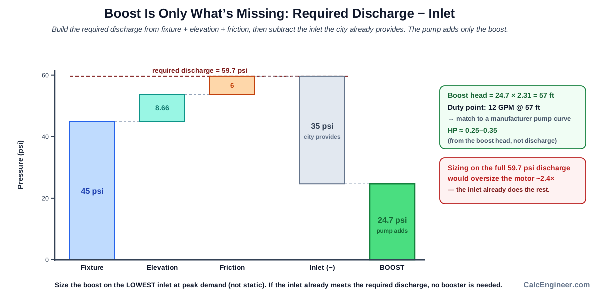
The boost head is the boost in feet (boost times 2.31), which is what you match to a pump curve.
Duty point. The pump is selected from a manufacturer curve at the design flow and the boost head, not from the horsepower. HP is an estimate that narrows the motor search.
Inlet verdict. If the lowest inlet is below the code minimum (commonly 20 psi), the booster cannot operate without a low-suction cutoff and water authority review. If the inlet is tight (within 10 psi of the minimum), a low-suction cutoff is advised.
Booster not needed. If the inlet already meets or exceeds the required discharge, the result is booster not needed, and no pump is sized. This is the most common error in booster projects: sizing a pump that is not required.
How to Use This Calculator
Choose the unit system (US or Metric) using the calculator's own selector. Every field, label, and result follows that selector.
Enter the peak demand in GPM, or switch to the fixture estimate and enter a fixture load in WSFU with the fixture type.
Enter the required fixture pressure at the highest and furthest fixture. The default is 40 psi, which is a common value for domestic service.
Enter the elevation rise from the pump to the highest fixture. The calculator converts this to a pressure loss at 0.433 psi per foot.
Enter the friction loss in psi from the pump to the furthest fixture at peak flow. Use a friction calculation or the pipe-sizing tools for this.
Enter the lowest inlet pressure at peak demand. This is the actual incoming pressure measured while the building is at full demand, not the static no-flow pressure.
Optionally enter the maximum inlet pressure and select the control mode, so the tool can check whether the low floors could be over-pressurized.
Click Calculate. Read the required discharge, boost, boost head, duty point, HP range, inlet verdict, and any over-pressure advisory.
The boost is sized on the lowest inlet at peak demand, not the average or the static no-flow pressure. Using a higher inlet undersizes the boost, so the top fixtures fall short when the city pressure is at its lowest.
Inputs & Outputs
Inputs
Outputs
Formula
Booster Pump Sizing Formula
All calculations in US units. SI inputs are converted internally before calculation.
US units: flow Q in GPM, pressures in psi, heads in feet.

1. Elevation loss
   elev_psi = elevation_rise_ft * 0.433            [psi]

2. Required discharge pressure
   required = fixture_pressure + elev_psi + friction + safety_margin   [psi]

3. Boost pressure (sized on the LOWEST measured inlet at peak demand)
   boost = required - inlet_min_measured            [psi]
   If boost <= 0: booster not needed. No head, no HP computed.

4. Boost head (for the pump curve)
   boost_head = boost * 2.31                        [ft]

5. Discharge pressures
   design_discharge = inlet_min_measured + boost = required   [psi]
   max_discharge    = inlet_max + boost (constant speed only) [psi]
   Over-pressure test:
     variable speed  -> check design_discharge
     constant speed  -> check max_discharge (if inlet_max given)
     inlet_max blank -> check design_discharge, note max inlet not evaluated
   If governing > max_pressure_limit (default 80 psi): PRV needed on low floors.

6. Pump power (uses BOOST head, not required-discharge head)
   WHP = Q * boost_head / 3960                     (water horsepower)
   BHP = WHP / efficiency                          (brake horsepower)
   efficiency: booster centrifugal about 0.50 to 0.70
   Show as a range: BHP_low = WHP / 0.70, BHP_high = WHP / 0.50

7. Inlet check (measured vs code minimum)
   inlet_margin = inlet_min_measured - inlet_code_min
   inlet_min_measured < inlet_code_min -> INLET BELOW MINIMUM (strong warning)
   0 <= inlet_margin <= 10 psi        -> INLET TIGHT (low-suction cutoff advised)
   inlet_margin > 10 psi              -> INLET OK

8. Pump count guidance (conceptual, not a code rule)
   < 15 GPM        -> single or duplex (residential, by redundancy need)
   15 to 150 GPM   -> duplex, alternating lead-lag (commercial)
   >= 150 GPM      -> triplex
SI mode: Elevation loss is 9.8 kPa per meter of rise. Head conversion: pressure in kPa divided by 9.81 gives meters of head. Boost head in meters = boost_kPa / 9.81. WHP in kW = rho * g * Q_m3s * head_m = 1000 * 9.81 * (Q_Lmin / 60000) * head_m. Displayed as kW. All other relations are identical in SI-consistent units.
QA benchmarks:
Case 1 (12 GPM, fixture 45 psi, elevation 20 ft, friction 6 psi, inlet 35 psi):
- Elevation loss: 20 * 0.433 = 8.66 psi. Required: 45 + 8.66 + 6 = 59.7 psi.
- Boost: 59.7 - 35 = 24.7 psi. Boost head: 24.7 * 2.31 = 57.1 ft. Duty point: 12 GPM at 57 ft.
- WHP: 12 * 57.1 / 3960 = 0.173 HP. BHP range: 0.247 to 0.346 HP.
Case 2 (50 GPM, fixture 40 psi, elevation 60 ft, friction 15 psi, inlet 40 psi):
- Elevation loss: 26.0 psi. Required: 81.0 psi. Boost: 41.0 psi. Head: 94.7 ft.
- WHP: 1.20 HP. BHP range: 1.7 to 2.4 HP. PRV needed (81.0 > 80 psi).
Pressure Boost vs Discharge Pressure
The required discharge pressure is the total pressure the building needs at the pump outlet: fixture residual pressure, elevation loss, friction loss, and safety margin added together. Boost pressure is not the same thing. Boost is only what the inlet cannot supply, which is required discharge minus the lowest inlet at peak demand.
Confusing these two numbers is the most common sizing error. A building that needs 60 psi at the pump but already receives 35 psi from the city needs only 25 psi of boost. Sizing the pump for 60 psi of boost instead of 25 psi oversizes the motor by more than twice and picks a pump that runs far to the left on its curve.
Booster Pump Duty Point
The duty point is the combination of flow and head where the pump must operate: design flow in GPM at the boost head in feet. It is the single point you match against a manufacturer pump curve. A pump that hits the duty point on its curve delivers the right flow and head at the same time.
Horsepower is only an estimate to narrow the motor search. The final pump and motor are selected by finding the model whose curve passes through or near the duty point at an acceptable efficiency. Selecting by HP alone, without checking the curve, is how pumps get sized for the wrong duty point.
Lowest Inlet Pressure at Peak Demand
The inlet pressure that sizes the boost is the lowest pressure the incoming supply actually delivers while the building is at full demand. That means the pressure measured at the pump inlet while occupants are using water, not the static no-flow pressure and not a reading taken on a quiet morning.
Static pressure is always higher than peak-demand pressure and makes the boost look smaller than it really is. A pump sized on static pressure underdelivers at the top fixtures the moment the building reaches peak demand and the city pressure drops. The only safe way to size the boost is from the lowest measured inlet under load.
Booster Pump Not Needed Check
If the lowest inlet pressure already meets or exceeds the required discharge, the boost is zero or negative and no booster is needed. This is not a failure case. It is the most common mistake in booster projects: specifying a pump for a building where the city supply is already adequate.
When the inlet is close to the required discharge but slightly below, a small local booster only at the top-floor zone can be more economical than a whole-building installation. The calculator flags the booster-not-needed condition and shows the margin so you can judge whether a partial solution makes more sense.
Booster Pump Horsepower
Booster horsepower is calculated from the flow and the boost head, not the required-discharge head. Water horsepower equals flow in GPM times boost head in feet, divided by 3,960. Brake horsepower adds pump efficiency: WHP divided by the efficiency, typically between 0.50 and 0.70 for a centrifugal booster.
Because efficiency varies by pump model and the exact operating point, the result is shown as a range. For 12 GPM at a 57-foot boost head, that range is about 0.25 to 0.35 HP. The actual motor comes from the selected pump. Using the required-discharge head instead of the boost head for the HP estimate oversizes the motor, because the inlet pressure is already doing part of the work.
PRV and Over-Pressure Check
The pressure at any fixture depends on where that fixture sits relative to the pump. On a booster installation the low floors see the highest pressure because they are closest to the pump outlet. Most codes limit fixture pressure to 80 psi, commonly IPC 604.8. If the design discharge exceeds that limit, pressure-reducing valves are required on the low floors.
For a constant-speed booster the discharge pressure is not fixed. It equals the inlet plus the fixed boost at every moment. When the city pressure rises toward its daily maximum, the discharge rises with it. A pump sized for 30 psi of boost at 40 psi inlet delivers 70 psi on design, but delivers 90 psi when the city rises to 60 psi. The maximum-inlet check catches this case before the installation is built.
Variable-Speed vs Constant-Speed Booster
A variable-speed booster uses a VFD to change the pump speed and hold a set discharge pressure. When the city inlet rises, the VFD slows the pump so the discharge stays at the setpoint. The low floors remain at or below the design pressure and the over-pressure check is essentially satisfied by the control system.
A constant-speed booster adds a fixed boost regardless of the inlet. It is simpler and less expensive, but the discharge pressure rises and falls with the inlet. Constant-speed control makes the over-pressure and maximum-inlet check essential. When a maximum inlet pressure is provided and the control mode is set to constant speed, the calculator evaluates the discharge at maximum inlet and flags any case where it exceeds the pressure limit.
What is Pressure Boost
Pressure boost is the amount of pressure a booster pump adds to water that already arrives under some pressure, from a city main, a break tank, or a rooftop tank. A booster is not the same as a well pump, which lifts water from a level below ground and must supply the full delivery pressure from static head. A booster starts with positive inlet pressure and adds only the missing part.
The boost needed for any installation is determined by one subtraction: required discharge pressure minus the lowest inlet pressure at peak demand. Everything else in the sizing calculation, the elevation, the friction, the fixture pressure, and the safety margin, feeds into that required discharge number. Once the boost is known, the pump duty point, the horsepower, and the inlet and over-pressure checks all follow directly.
Key Facts
- Boost is only the pressure the pump adds: required discharge minus the inlet. If the building needs 60 psi and the inlet provides 35 psi, the boost is 25 psi, not 60.
- Required discharge is built from four parts: fixture residual pressure, elevation loss (0.433 psi per foot), friction, and safety margin.
- Size the boost on the lowest inlet at peak demand, not the static no-flow pressure. Static pressure is always higher and makes the boost look smaller than it is.
- Boost head in feet equals the boost in psi times 2.31. The duty point is the design flow at that head, matched to a pump curve.
- HP uses the boost head, not the full required-discharge head. Using the discharge head oversizes the motor because the inlet pressure is doing part of the work.
- If the inlet already meets the required discharge, the boost is zero or negative and no booster is needed. A good sizing tool says so instead of inventing a pump.
- Most codes require the inlet to stay at or above about 20 psi so the booster does not pull the city main negative and risk backflow contamination.
- A constant-speed booster adds a fixed boost, so when the city inlet rises, the discharge rises with it. A pump sized for 30 psi boost at 40 psi inlet delivers 70 psi, but at 60 psi inlet delivers 90 psi, over the 80 psi limit.
- Variable-speed boosters hold a set discharge pressure, keeping the delivered pressure steady and avoiding over-pressurization of the low floors.
Applications
- Sizing a booster for a house or building with low city pressure
- Sizing a booster for a multi-story building where the upper floors fall short of the required pressure
- Checking whether a booster is needed at all, or whether the inlet is already adequate
- Deciding whether a local top-floor booster is better than a whole-building installation
- Finding the duty point (flow at boost head) to match against a manufacturer pump curve
- Estimating the horsepower and the number of pumps for a booster package
- Screening whether the low floors will need pressure-reducing valves or pressure zoning
- Sizing a booster fed from a break tank or rooftop tank
- Checking a constant-speed booster for over-pressure when the city pressure is high
- Verifying an existing booster design against the actual measured inlet pressure at peak demand
Example Calculation
Example 1: Small Residential Booster
Given: 12 GPM, fixture pressure 45 psi, elevation 20 ft, friction 6 psi, lowest inlet 35 psi.
Elevation loss = 20 ft * 0.433 psi/ft = 8.66 psi
Required discharge = 45 + 8.66 + 6 = 59.7 psi
Boost = 59.7 - 35 = 24.7 psi
Boost head = 24.7 * 2.31 = 57.1 ft
Duty point: 12 GPM at 57 ft
WHP = 12 * 57.1 / 3960 = 0.17 HP
BHP range (eff 50-70%): 0.25 to 0.35 HP
Inlet 35 psi is 15 psi above the 20 psi code minimum, so INLET OK. Design discharge 59.7 psi is below 80 psi, so no PRV needed. Single or duplex booster.
Example 2: Multi-Story, PRV Required
Given: 50 GPM, fixture 40 psi, elevation 60 ft, friction 15 psi, lowest inlet 40 psi.
Elevation loss = 60 * 0.433 = 26.0 psi
Required = 40 + 26 + 15 = 81.0 psi
Boost = 81.0 - 40 = 41.0 psi
Boost head = 41.0 * 2.31 = 94.7 ft
Duty point: 50 GPM at 95 ft
WHP = 50 * 94.7 / 3960 = 1.20 HP
BHP range: 1.7 to 2.4 HP
Design discharge 81.0 psi exceeds 80 psi, so pressure-reducing valves are required on the low floors.
Example 3: Booster Not Needed
Given: Fixture 40 psi, elevation 10 ft, friction 5 psi, lowest inlet 55 psi.
Elevation loss = 10 * 0.433 = 4.33 psi
Required = 40 + 4.33 + 5 = 49.3 psi
Boost = 49.3 - 55 = negative (-5.7 psi)
Result: BOOSTER NOT NEEDED. The inlet already exceeds the required discharge. No pump is sized. If only the top floors fall short, a small local solution may be better.
Example 4: Constant-Speed Over-Pressure Caught by Maximum Inlet
Given: 40 GPM, required discharge 70 psi, lowest inlet 40 psi, boost 30 psi, maximum inlet 60 psi, constant-speed pump.
Design discharge = 40 + 30 = 70 psi (below 80, looks fine)
Max discharge    = 60 + 30 = 90 psi (above 80, PRV needed)
The design discharge looked fine, but the constant-speed pump adds a fixed 30 psi. When the city rises to 60 psi, the discharge becomes 90 psi. PRV required on the low floors, even though the design point was under 80 psi.
Example 5: Inlet Below Code Minimum
Given: 30 GPM, fixture 45 psi, elevation 30 ft, friction 8 psi, lowest inlet 15 psi.
Elevation loss = 30 * 0.433 = 13.0 psi
Required = 45 + 13 + 8 = 66.0 psi
Boost = 66.0 - 15 = 51.0 psi, boost head = 117.8 ft
Sizing is shown, but INLET BELOW MINIMUM: 15 psi is below the 20 psi code minimum. A low-suction cutoff is required and the water authority must be consulted.
Standards & References
- Xylem Bell and Gossett, Domestic Water Pressure Booster Design Manual (TEH-1096B) — booster duty-point method, boost head, efficiency, and HP estimation basis
- Bell and Gossett, Pressure Booster System Packages — packaged booster selection guidance
- Grundfos, Domestic Water Booster Catalogue — booster pump curves, control modes, and sizing examples
- IPC 604.8 — maximum static pressure at fixtures commonly limited to 80 psi; local amendments may differ
- IPC Appendix E, Table E103.3 — Hunter's Curve for WSFU to GPM conversion (flush tank and flush valve)
- Local water authority cross-connection control rules — minimum inlet pressure commonly 20 psi to prevent negative-pressure backflow; confirm the local value
Units
The calculator works in either US or metric units, set by its own selector. Switching the unit system converts the values you entered, it does not reinterpret them. US mode: flow in GPM, pressure in psi, head in feet, power in HP. Metric mode: flow in L/min, pressure in kPa, head in meters, power in kW. Reference conversions: 1 GPM = 3.785 L/min, 1 psi = 6.895 kPa, 1 psi of water = 2.31 ft of head, elevation costs 0.433 psi per foot or 9.8 kPa per meter, 1 HP = 0.746 kW.
Limitations
- This calculator is a sizing aid for the duty point and horsepower. Final selection uses a manufacturer pump curve at the design flow and boost head.
- It does not size the pressure or hydropneumatic tank, the acceptance volume, or the pre-charge.
- It does not design the control scheme, the PRV bleed-off, or the variable-speed setpoint in detail.
- It does not check NPSH available or size the suction pipe.
- It does not design floor-by-floor pressure zoning for tall buildings.
- Horsepower is an estimate from an efficiency band. The actual motor comes with the pump selected from a manufacturer curve.
- Pump count guidance is conceptual. Final staging and standby depend on building type, redundancy, and local code.
- The minimum inlet threshold (commonly 20 psi) and the maximum pressure limit (commonly 80 psi) are set by local code and the water authority, and project requirements may differ.
- This calculator does not cover the electrical package, wire sizing, breaker, or voltage drop for the booster motor.
- Water at normal temperature and specific gravity 1.0 assumed throughout.
Common Mistakes to Avoid
- Sizing the pump on the full required discharge pressure instead of the boost. The boost is only the pressure missing after the inlet is counted.
- Using the static, no-flow city pressure as the inlet. Size the boost on the lowest inlet at peak demand, when the pressure is at its worst.
- Using an average or high inlet pressure. That undersizes the boost, so the top floors fall short when the city pressure drops.
- Forgetting the maximum inlet pressure check for a constant-speed booster. A fixed boost added to a high inlet can push the low floors over the pressure limit.
- Boosting from an inlet below the code minimum without a low-suction cutoff. Pulling the city main negative can draw in contamination.
- Sizing a booster when the inlet is already adequate. If the inlet meets the requirement, no booster is needed.
- Using the full discharge head for the HP estimate. Use the boost head, or the motor is oversized.
- Ignoring the low floors on a constant-speed booster. A high inlet plus a fixed boost can push the base of the building over 80 psi.
- Confusing a booster with a well pump. A booster starts with positive inlet pressure and adds only the missing boost. A well pump starts from a pumping water level and is sized on the full lift.
- Treating the HP estimate as the final selection. The pump curve at the duty point, not the HP, sets the pump and motor choice.
Frequently Asked Questions
How do I size a booster pump?
What is boost pressure and how much do I need?
How do I know if I even need a booster pump?
Should I use static pressure or pressure at peak demand for sizing?
What is the minimum inlet pressure for a booster pump?
How many horsepower does a booster pump need?
Why can a constant-speed booster over-pressurize the low floors?
What is the difference between a variable-speed and a constant-speed booster?
Is a booster pump the same as a well pump?
Can I size a booster by horsepower alone?
Do I need a pressure-reducing valve with a booster?
Frequently Used Together
Engineers often use these calculators in combination for complete project workflows:
Related Calculators
Explore similar calculators that might be useful for your project:
Plumbing Quick Reference — Keep It On Your Phone On Site
A 10-page field reference for catching pressure, velocity, slope, and pump-sizing mistakes before you order pipe, close a wall, or add a booster.
- Velocity limits, fixture pressure minimums, drain slope, and the 80 psi ceiling in one table
- Worked examples that show why a single pressure number gives four different answers
- Keep it on your phone, or print the two field-check pages
Free PDF. Calculators stay free. Unsubscribe anytime.
Calculate
The calculator's own unit selector governs all fields, labels, and results. Switching converts the values you entered, it does not reinterpret them.
Direct entry is preferred when a measured or designed flow is known. WSFU is a quick estimate using Hunter's Curve. For a full fixture count, use the Water Supply Fixture Unit Calculator.
Peak simultaneous flow, not the sum of all fixtures. Typical residential: 10 to 20 GPM. Commercial: size from fixture demand or measured peak flow.
Residual pressure needed at the highest and furthest fixture. Common values: 40 psi general domestic service, 15 to 20 psi for flush tanks, 35 psi or more for flushometer valves. Default 40 psi.
Vertical rise from the pump to the highest fixture. Water loses 0.433 psi per foot of rise, or about 9.8 kPa per meter. Roughly 10 to 12 ft per floor in commercial buildings.
Pressure lost to pipe and fitting friction from the pump to the furthest fixture at peak flow. Use the Hazen-Williams pipe flow or water pipe sizing calculators to estimate this.
Additional pressure added to the required discharge for design margin. Common values: 5 to 10 psi for residential, 0 when friction and fixture pressure already include adequate margin.
The lowest pressure the incoming supply actually provides at the pump inlet while the building is at peak demand. Do not use the static no-flow pressure or an average. This single number defines the boost. If this is unknown, a pressure test under load is needed before sizing.
The highest incoming pressure, used to check whether a constant-speed booster could over-pressurize the low floors when the city pressure is high. Leave blank to check only the design discharge.
Variable-speed boosters hold a set discharge pressure. They avoid over-pressure when the inlet rises. Constant-speed boosters add a fixed boost, so the discharge moves up and down with the inlet, which needs a maximum-inlet check.
The regulatory or code threshold the inlet must stay at or above, commonly 20 psi, to prevent the booster from pulling the city main into negative pressure. Confirm the local value with the water authority. This is separate from the measured inlet above.
The maximum static pressure allowed at fixtures, commonly 80 psi per IPC 604.8. If the governing discharge exceeds this, low floors need pressure-reducing valves. Confirm the local code limit.
Centrifugal booster efficiency at the duty point. If left blank, the calculator uses the typical band of 50 to 70% and shows a BHP range. Enter a specific efficiency to narrow the range.