Valve Cv Flow Calculator — Flow, Cv & Pressure Drop
On this page
Calculate
Choose which quantity to solve for. The other two become required inputs.
Cv is US gpm at 1 psi drop; Kv is m³/h at 1 bar drop. Cv = 1.156 × Kv.
Differential pressure across the valve, P1 minus P2. Not the upstream system pressure.
Specific gravity relative to water at 60 deg F. Water 1.00, light oil about 0.85, 50% glycol about 1.04. Non-water presets set SG only; enter vapor pressure directly for cavitation screening.
Absolute inlet pressure (gauge plus 14.7 psia). Needed only for the choked-flow and cavitation check. If you have a gauge reading, add local atmospheric pressure first.
For water, a temperature can be used to look up vapor pressure. For other fluids, enter vapor pressure directly.
Used to look up water vapor pressure. Valid for water only (fluid preset = Water). Range 32 to 300 deg F.
Sets the pressure recovery factor FL used in the choked-flow calculation. Default FL values are screening estimates. Use the manufacturer FL for final sizing or cavitation checks.
Overview
The valve flow coefficient Cv ties together three quantities: the flow through a valve, the pressure drop across it, and the valve's capacity. Give the calculator any two of the three and it returns the third, corrected for the fluid's specific gravity. Cv is defined as the number of US gallons per minute of water at 60 deg F that pass through the valve at a pressure drop of 1 psi. The metric equivalent, Kv, is cubic meters per hour of water at a pressure drop of 1 bar.
Using only the basic Cv equation, a high-pressure-drop liquid valve can appear to pass far more flow than it physically can. Once the pressure at the narrowest point in the valve falls to the liquid vapor pressure, the flow chokes: extra pressure drop produces no more flow, and the valve either cavitates or flashes. This tool screens for that limit using the valve's pressure recovery factor FL and the fluid's vapor pressure, caps the flow at the choked value when that limit is reached, and classifies the operating regime as Normal, Approaching Choke, Choked Cavitation, or Choked Flashing.
This is a liquid-service tool for water and other liquids entered by specific gravity, per ISA-75.01.01-2012 and IEC 60534-2-1:2011. It is not for gas, vapor, or steam, which follow different compressible equations.
What to Look at First
Solved value. The primary result is the quantity you asked for: flow in gpm or m³/h, required Cv (also shown as Kv), or pressure drop in psi or bar. Both Cv and Kv are always shown so you can compare valve datasheets regardless of the unit convention used.
Flow regime. If you entered inlet pressure P1, vapor pressure or water temperature, and valve type, the tool shows whether the operating point is Normal, Approaching Choke, or Choked, and if choked, whether the downstream state is Cavitation or Flashing. Understanding which regime you are in determines what action to take if the valve needs to be changed.
Choke utilization. When regime inputs are present, the choke utilization (actual dP divided by dP_choked) tells you how close the valve is to its liquid choked-flow limit. Below 85% is normal operating range; 85-100% is approaching choke and warrants a manufacturer confirmation.
Target Unachievable. When solving for pressure drop, if the result would exceed the choked-flow limit, the tool reports this directly and shows the maximum achievable flow at the choked limit instead of a pressure drop that cannot deliver the requested flow.
How to Use This Calculator
Select what to solve for: Flow (given Cv and dP), Required Cv (valve sizing, given flow and dP), or Pressure Drop (given flow and Cv).
Select the unit system (Imperial or Metric) using the calculator's own selector. Every field, label, and result follows that selector.
Enter the two known values for the selected target. For example, to size a valve, enter the flow you need and the pressure drop you can spend.
Set the fluid. Water is the default (SG 1.00). Choose another preset or select Custom SG and enter a value.
Optional, for the choked-flow and cavitation check: enter the absolute inlet pressure P1, then either a water temperature (for automatic vapor pressure lookup) or a direct vapor pressure Pv. Also select the valve type, which sets the pressure recovery factor FL.
Click Calculate. Read the solved value, the Cv and Kv, and the regime verdict if regime inputs were entered.
For Solve for Pressure Drop: if the tool reports Target Unachievable, the requested flow exceeds the choked capacity. Use a larger Cv, a different valve style, or a higher inlet pressure.
All pressure inputs for the choked-flow check (P1 and Pv) must be absolute pressures. If you have a gauge reading, add local atmospheric pressure (about 14.7 psi or 1.013 bar) before entering it.
Inputs & Outputs
Inputs
Outputs
Formula
Calculator Formula
This calculator solves the ISA-75.01.01 / IEC 60534-2-1 liquid flow equations and applies the choked-flow guard when regime inputs are available.
Core Liquid Cv Equations (US units: Q in gpm, dP in psi, SG water = 1)
Flow:      Q  = Cv × √(dP_eff / SG)
Required:  Cv = Q × √(SG / dP_eff)
Drop:      dP = SG × (Q / Cv)²
Coefficient Conversion
Cv = 1.156 × Kv
Kv = 0.865 × Cv
Outlet Pressure (absolute)
P2 = P1 − dP
Choked-Flow Limit (ISA-75.01.01 / IEC 60534-2-1)
dP_choked = FL² × (P1 − FF × Pv)
FF = 0.96 − 0.28 × √(Pv / Pc)     (about 0.96 for water near ambient)
Where: P1 = absolute inlet pressure, Pv = vapor pressure at flowing temperature, Pc = fluid critical pressure (water Pc = 3206 psia), FL = pressure recovery factor.
Effective Pressure Drop
dP_eff = dP           if dP < dP_choked (or regime not evaluated)
dP_eff = dP_choked    if dP ≥ dP_choked (choked)
Regime Classification
U = dP / dP_choked   (choke utilization)

U < 0.85           → Normal
0.85 ≤ U < 1.00    → Approaching Choke
U ≥ 1.00           → Choked, then:
  P2 >  Pv          → Cavitation
  P2 ≤ Pv          → Flashing
FL Defaults by Valve Type (screening values)
Globe 0.90, Gate 0.80, Ball 0.68, Butterfly 0.60
SI mode: same equations with Q in m³/h, dP in bar, Kv. L/min converts to m³/h (÷ 16.667) and kPa converts to bar (÷ 100) before the formula. No second formula block.
Physical validity: P2 ≥ P1 (dP ≤ 0), P2 ≤ 0 absolute, or Pv ≥ P1 all return PHYSICALLY-INVALID.
What Is a Valve Flow Coefficient (Cv)?
The flow coefficient Cv is a single number that describes how much a valve restricts flow. By definition, a valve with a Cv of 1 passes 1 US gallon per minute of water at 60 deg F with a pressure drop of 1 psi. A valve with a Cv of 25 passes 25 gpm of water at that same 1 psi drop. The larger the Cv, the greater the flow for a given pressure drop. Cv only becomes a flow rate when combined with a pressure drop and the fluid specific gravity.
The metric equivalent, Kv, works the same way in SI units: cubic meters per hour of water at a pressure drop of 1 bar. The conversion between them is fixed: Cv equals 1.156 times Kv. Because Cv is measured on water, other liquids are handled with specific gravity. A denser fluid passes less flow for the same Cv and pressure drop; a lighter fluid passes more. Flow scales with 1 over the square root of specific gravity.
Cv to Flow Calculation
This solve target answers a simple question: given an installed valve with a known Cv rating and a measured pressure drop, how much flow does the valve pass? Enter the valve Cv from the manufacturer datasheet and the differential pressure across the valve. The calculator applies Q = Cv times the square root of pressure drop divided by specific gravity and returns the flow in US gpm (Imperial) or m³/h (SI).
Water at 60 deg F is the baseline at SG 1.00. For other liquids, set the specific gravity in the Fluid field. A lighter fluid passes more flow for the same Cv; a denser fluid passes less. For example, 50% propylene glycol at SG 1.04 passes about 2 percent less flow than water through the same valve at the same pressure drop. If inlet pressure and vapor pressure inputs are present, the tool also checks whether the operating point is normal or choked before returning the flow.
Required Cv for Valve Sizing
This solve target answers the core valve selection question: what Cv does the valve need to pass the required flow at the available pressure drop? Enter the design flow and the pressure drop you can afford across the valve, and the calculator returns the required Cv and its Kv equivalent. This number is the minimum capacity you need at the design point, not the valve rating you order.
Select a valve whose rated Cv is above the required value, and size it so the required Cv falls within roughly 20 to 80 percent of the valve rated Cv at full travel. A valve running near its maximum Cv has no room to increase flow when system demand rises. One barely cracked open sits in an unstable part of its control range. For example, if the required Cv is 25, choose a valve rated at least Cv 30 and ideally in the Cv 32 to 50 range so the operating point sits in the middle of travel.
Valve Pressure Drop from Cv
This solve target returns the differential pressure a given valve adds to the system at a specified flow. Enter the flow and the valve Cv and the calculator returns dP = SG times the square of Q divided by Cv. The result is the pressure drop across the valve alone, not the system supply pressure. Subtract the returned dP from the absolute inlet pressure P1 to get the outlet pressure P2.
If P1 and regime inputs are present, the result is checked against the choked-flow limit. If the requested flow exceeds what the valve can pass at the choked pressure drop, the tool reports Target Unachievable and shows the maximum flow the valve can deliver at that inlet pressure instead of a pressure drop that cannot be reached. In that situation, use a larger Cv, a valve style with a higher pressure recovery factor FL, or a higher inlet pressure.
Choked Flow in Liquid Valves
The basic Cv equation assumes flow keeps rising with the square root of pressure drop. Real liquid valves do not. As the fluid speeds up through the valve, its pressure drops to a minimum at the vena contracta. When that minimum pressure falls to the liquid vapor pressure, the liquid starts to vaporize and the flow chokes. Past that point, adding more pressure drop produces no more flow.
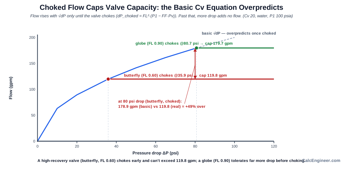
The choked-flow limit is dP_choked = FL squared times (P1 minus FF times Pv), where FL is the valve pressure recovery factor, P1 is the absolute inlet pressure, Pv is the vapor pressure, and FF is about 0.96 for water near ambient. A globe valve with FL around 0.90 tolerates a high pressure drop before choking. A butterfly valve with FL around 0.60 chokes at a much lower pressure drop. The calculator caps flow at the choked maximum when that limit is reached and tells you which regime you are in.
Cavitation and Flashing
Cavitation and flashing are the two conditions that occur once a liquid valve is choked, and they are distinguished by the outlet pressure relative to vapor pressure. If P2 stays above the vapor pressure, the vapor bubbles formed inside the valve collapse downstream. That collapse is violent and erodes the valve and downstream piping. This is cavitation, and it is addressed with anti-cavitation trim, a different valve style, or staged pressure reduction.
If P2 is at or below vapor pressure, the fluid does not re-condense and exits as a two-phase mixture. This is flashing, a thermodynamic condition that trim selection cannot fix. Flashing is handled with erosion-resistant materials and enlarged downstream piping to manage the two-phase flow.
Key Facts
- Cv is defined as US gallons per minute of water at 60 deg F that pass through a valve at a pressure drop of 1 psi. A Cv of 1 is a small valve; industrial control valves range from Cv 1 to several thousand.
- Cv equals 1.156 times Kv. This is a fixed unit-system conversion, not a rounded approximation.
- A denser fluid passes less flow for the same Cv and pressure drop: flow scales with 1 over the square root of specific gravity.
- Choked flow begins when the pressure at the valve vena contracta falls to the liquid vapor pressure. Beyond that limit, the basic square-root Cv equation overpredicts flow, which is why the choked-flow guard matters.
- The pressure recovery factor FL is valve-style specific. Globe valves (FL about 0.90) tolerate a high pressure drop before choking; butterfly valves (FL about 0.60) choke at a much lower pressure drop.
- Cavitation occurs when choked flow produces a P2 above vapor pressure: vapor bubbles form and violently collapse, eroding the valve and downstream piping.
- Flashing occurs when P2 is at or below vapor pressure: the fluid exits as a two-phase mixture that cannot re-condense. Flashing is a thermodynamic condition that trim selection cannot fix.
- For good control, the required Cv should fall within roughly 20 to 80 percent of the valve's rated Cv. A valve running near fully open has little room to increase flow.
Applications
- Sizing control valves and balancing valves for hydronic heating and chilled-water systems.
- Selecting solenoid valves and process valves for a target flow at a known pressure drop.
- Checking whether an existing valve will pass a higher flow after a system change.
- Screening high-pressure-drop service for cavitation or flashing risk before choosing a valve style or trim.
- Estimating the pressure drop a given valve adds at a design flow rate.
- Comparing how a globe valve and a butterfly valve behave at high pressure drop.
- Water treatment, irrigation, pump bypass and recirculation lines, and general liquid piping.
Example Calculation
Example 1: Solve for Flow
Given: Cv 10, pressure drop 25 psi, water (SG 1.00).
Q = Cv × √(dP / SG) = 10 × √(25 / 1.00) = 10 × 5.000 = 50.0 gpm
Kv equivalent: Kv = 0.865 × 10 = 8.65. In metric: 8.65 × √(1.724 bar) = 11.36 m³/h, which equals 50.0 gpm.
Example 2: Solve for Required Cv (sizing)
Given: Flow 100 gpm, pressure drop 16 psi, water.
Cv = Q × √(SG / dP) = 100 × √(1.00 / 16) = 100 × 0.2500 = 25.0 (Kv 21.6)
Select a valve rated above Cv 25, ideally so the required Cv falls near the middle of its travel.
Example 3: Choked Flow (high-recovery valve)
Given: Cv 20, water at 70 °F (Pv 0.363 psia), inlet P1 100 psia, butterfly valve (FL 0.60), pressure drop 80 psi.
FF = 0.96 − 0.28 × √(0.363 / 3206) = 0.96 − 0.28 × 0.01065 = 0.957
dP_choked = 0.60² × (100 − 0.957 × 0.363) = 0.36 × 99.65 = 35.9 psi
At 80 psi, the valve is choked (U = 80/35.9 = 2.23). Maximum flow: 20 × √(35.9) = 119.8 gpm. A naive full-80-psi calculation would claim 20 × √80 = 178.9 gpm, an overestimate of about 49 percent. P2 = 100 − 80 = 20 psia, above Pv 0.363 psia: regime is CHOKED, CAVITATION.
Example 4: Target Unachievable
Given: Solve for dP, flow 178.9 gpm, Cv 20, P1 100 psia, butterfly FL 0.60, Pv 0.363 psia.
Basic dP = 1.00 × (178.9 / 20)² = 80 psi, but dP_choked = 35.9 psi. The flow of 178.9 gpm cannot be achieved by increasing pressure drop. Result: TARGET UNACHIEVABLE. Maximum flow at the choked limit: 119.8 gpm.
Standards & References
- ANSI/ISA-75.01.01-2012 (IEC 60534-2-1 MOD), Flow Equations for Sizing Control Valves: primary standard for the Cv equation and choked-flow limit used on this page
- IEC 60534-2-1:2011, Industrial-process control valves, Sizing equations for fluid flow: international standard defining Kv and the liquid sizing equations
- Fisher Control Valve Handbook (Emerson): comprehensive reference for Cv, FL, cavitation, and flashing in control valves
- Crane TP-410, Flow of Fluids Through Valves, Fittings, and Pipe: industry reference for liquid flow and pressure drop through valves
- Engineering ToolBox, Flow Coefficients Cv and Formulas: supporting reference for Cv and Kv conversion and applications
Limitations
- This calculator is for single-phase liquid flow only. Do not use it for gas, vapor, steam, or two-phase flow.
- The turbulent-flow assumption means no viscosity, valve size, or Reynolds number input is included. For viscous oils, low flows, or small valves a Reynolds-number correction (FR) may be needed; v1 does not compute it.
- No piping-geometry factor (Fp) is applied. The tool sizes the valve alone; reducers and expanders attached to the valve reduce effective capacity.
- Choked-flow and cavitation screening uses a typical FL by valve style (screening values). Use the manufacturer FL and trim data for final cavitation assessment.
- For non-water fluids, vapor pressure must be entered directly. The tool does not infer Pv from temperature for non-water fluids, and FF is assumed 0.96 when critical-pressure data is not available.
- The required Cv should fall within roughly 20 to 80 percent of the valve's rated Cv for good control; this is general guidance and depends on the valve flow characteristic.
Common Mistakes to Avoid
- Using system pressure instead of the pressure drop across the valve. Pressure drop is P1 minus P2, not the line pressure.
- Ignoring choked flow on high-recovery valves. A butterfly valve or ball valve chokes at a much lower pressure drop than a globe valve. The basic equation can overstate flow by up to 50 percent.
- Using gauge pressure where absolute pressure is needed for the choked-flow check. Add 14.7 psi (or 1.013 bar) to any gauge reading before entering P1 or Pv.
- Treating default FL as manufacturer data. Default FL values by valve style are screening estimates. Final cavitation and flashing checks require the manufacturer FL for the selected valve and trim.
- Sizing a control valve to run at or near fully open rated Cv. Aim for the required Cv to fall around 20 to 80 percent of the valve's rated Cv for controllability.
- Applying the liquid Cv equation to gas or steam. Compressible fluids use different sizing equations with an expansion factor.
- Forgetting specific gravity for non-water fluids. A lighter fluid passes more flow for the same Cv; a heavier fluid passes less.
- Sizing on the pressure drop without checking whether the valve is choked. A higher pressure drop past the choked limit adds no flow.
Frequently Asked Questions
What is a valve flow coefficient (Cv)?
What is the difference between Cv and Kv?
How do I find the flow through a valve from its Cv?
What is choked flow and why does it matter?
What is the difference between cavitation and flashing?
Why does a butterfly valve choke sooner than a globe valve?
Do I use gauge or absolute pressure for P1 and Pv?
What Cv should I select for good control?
Can I use this calculator for gas or steam?
Why is my calculated flow lower than the basic Cv equation predicts?
Frequently Used Together
Engineers often use these calculators in combination for complete project workflows:
Related Calculators
Explore similar calculators that might be useful for your project:
Plumbing Quick Reference — Keep It On Your Phone On Site
A 10-page field reference for catching pressure, velocity, slope, and pump-sizing mistakes before you order pipe, close a wall, or add a booster.
- Velocity limits, fixture pressure minimums, drain slope, and the 80 psi ceiling in one table
- Worked examples that show why a single pressure number gives four different answers
- Keep it on your phone, or print the two field-check pages
Free PDF. Calculators stay free. Unsubscribe anytime.
Calculate
Choose which quantity to solve for. The other two become required inputs.
Cv is US gpm at 1 psi drop; Kv is m³/h at 1 bar drop. Cv = 1.156 × Kv.
Differential pressure across the valve, P1 minus P2. Not the upstream system pressure.
Specific gravity relative to water at 60 deg F. Water 1.00, light oil about 0.85, 50% glycol about 1.04. Non-water presets set SG only; enter vapor pressure directly for cavitation screening.
Absolute inlet pressure (gauge plus 14.7 psia). Needed only for the choked-flow and cavitation check. If you have a gauge reading, add local atmospheric pressure first.
For water, a temperature can be used to look up vapor pressure. For other fluids, enter vapor pressure directly.
Used to look up water vapor pressure. Valid for water only (fluid preset = Water). Range 32 to 300 deg F.
Sets the pressure recovery factor FL used in the choked-flow calculation. Default FL values are screening estimates. Use the manufacturer FL for final sizing or cavitation checks.