Hot Water Recirculation Pump Sizing Calculator — Heat Loss Flow and the 2 ft/s Ceiling
On this page
Calculate
This selector governs every field, label, result and export on this page, and it takes priority over the site header switch. Switching converts the values you entered rather than reinterpreting them, so 20,000 BTU/h becomes 5,861 W and returns to exactly 20,000 when you switch back. Nominal pipe sizes stay in inches in both systems, because that is how copper tube is specified and ordered, and the bore rather than the nominal size appears in every equation. A temperature drop converts by dividing by 1.8 without the 32 degree offset, because a difference has no zero point to shift.
The Design Objective
This is the first question because it decides which heat loss belongs in the flow. Where the criterion is the temperature arriving at the farthest fixture, the supply piping loss to that fixture is what published guidance uses, because the return leg is downstream of the fixture and its losses do not affect what arrives there. Where the criterion is a minimum held everywhere in the loop, or a minimum return temperature, the return losses are included and the temperature drop is reconsidered against that objective. A designer working to a return temperature target with a supply only heat loss will undersize the flow.
The estimate route is not implemented in this version and returns a state rather than a number. A real estimate needs published BTU per hour per foot figures by pipe size, insulation state and temperature difference, and the heat loss is the input the flow, the velocity verdict and the pump selection all derive from, so a figure invented from a rule of thumb would propagate into every one of them at once. The distinction stays visible because it matters, and the route names where to get the figure instead of guessing at it.
Ten degrees Fahrenheit, which is 5.6 Celsius degrees, is the common design assumption, and five is used where tighter temperature control is required. Neither is universally mandated. A larger drop needs less flow, which is easier on the pump and the pipe, and it delivers cooler water at the far fixture so the occupant runs the tap longer and draws more hot water. This is a temperature difference rather than a level, so it converts by dividing by 1.8 with no 32 degree offset.
The Piping
This version carries copper velocity guidance and copper Type L bores only. Another material returns an out of scope state with no velocity verdict, because PEX, CPVC and other plastic systems carry manufacturer specific velocity and temperature limits and the erosion mechanism that governs copper does not transfer to them.
Not the return line by default. The recirculation flow is the same through every segment of the loop, so the narrowest pipe carrying it governs the velocity. In many systems that is the return, and it is not always: where a supply main necks down before the last fixture and the recirculation flow passes through it, that segment governs instead. Finding it is a drawing exercise rather than a calculation. Trace the path from the pump discharge back to the pump suction, note every change of size, and use the smallest.
The Head (all optional)
Measured from the pump to the farthest point and back. Leave it blank and the page still returns the flow and the velocity verdict, and reports the head and the duty point as not evaluated rather than as met.
A design allowance for a route that is not yet drawn, not a measurement, and it is scale dependent. On a published example of a 3,100 foot loop the fittings added about 2 percent to each long run, nowhere near 50. The larger figures belong to a short loop full of changes of direction, which is where a recirculation circuit usually is. If you have walked the route and your length already carries the equivalent lengths, add nothing.
Defaults to 2 if left blank, which published design guidance gives as a working value. This is a target the designer selects pipe to meet rather than a gradient computed from the bore and the flow: at 4 gallons per minute in three quarter inch copper the actual Hazen-Williams gradient with C of 140 is nearer 4.7 feet per 100 feet, more than twice the allowance. The value is a ratio, so it reads the same in both unit systems.
Balancing valves, thermostatic recirculation valves, check valves, isolation valves, strainers and the heater or storage vessel. Published guidance puts these on the return connections at the water heater, at the pump and at any thermostatic mixing valve cold water inlet. Until they are included the duty point is preliminary, and the result says so rather than presenting the friction head as the total.
The Checks (all optional)
The 2 foot per second default comes from code commentary on limitation of velocity, which states the ordinary figures are too great where the flow is continuous, and from an ASPE Pipeline article that recommends designing all hot water circulating systems below 2. The 3 foot figure is the top of the Copper Development Association range for hot water above 140 F and the figure a published forensic account of a recirculation failure recommends. Selecting it is a deliberate, less conservative choice and the result says so. The 5 to 8 feet per second figure familiar from cold water distribution is never applied on this page.
Used for the temperature caution only. Heating water above 140 F accelerates erosion corrosion, which is why the copper guidance drops from 4 to 5 feet per second below that figure to 2 to 3 above it. This is a temperature level rather than a difference, so it converts with the 32 degree offset.
Without balancing, the flow takes the path of least resistance and the short circuits take most of it, so the near branches run fast and the far branch, the one the design was built for, runs slow. That is an erosion problem and a temperature problem from one cause. A single loop with no branches does not have that failure mode, so the result distinguishes the two rather than issuing the same warning to both.
The flow is directly proportional to the heat loss, so whatever insulation does to the heat loss it does to the flow and to the velocity, one for one. That makes it a sizing input rather than an efficiency measure. The effect belongs inside the heat loss figure you enter rather than as a factor applied to the answer.
Overview
A recirculation pump is not sized to deliver water to anyone. It is sized to replace the heat the loop loses, so the flow comes from a heat loss divided by a temperature drop, and nothing about the fixtures enters it. A loop losing 20,000 BTU per hour at a 10 degree drop needs 4 gallons per minute whether it serves one bathroom or forty.
Two things follow that surprise people, and both push toward a smaller pump than instinct suggests.
There is no static head in an operating loop. Water rises through the supply and returns down the other leg, and the returning column pushes down with the force the rising column resists, so the two cancel and the pump only overcomes friction. A published ASPE presentation states it in those words: the pump head is determined from the piping system's friction and pressure loss, no static head. A residential worked example arrives at 1.9 gallons per minute at 5.2 feet of head, and even a 3,100 foot commercial loop comes out at 31.5 feet. Adding the building height is the fastest way to oversize a recirculation pump by an order of magnitude.
And the pump has to be small because the flow never stops. Copper guidance allows higher velocities in cold and intermittent service, up to 5 to 8 feet per second on cold water. For continuously circulating hot water this calculator uses 2 feet per second by default, because the velocity is not a peak that passes during a shower but the condition the pipe sits in every hour for twenty years. Above it the tube erodes from the inside, and published guidance names an oversized pump as the number one cause of pinhole leaks in recirculation lines.
The two errors compound. A pump sized against a static head that does not exist drives the loop far above the ceiling, and the pipe pays for the arithmetic years later.
What to Look at First
Read the velocity before the flow. The flow arithmetic can be perfectly correct and the design still wrong, because a recirculation pump runs continuously and the velocity it produces is the condition the copper lives in rather than a peak that passes. Exceeding the ceiling fails the result here rather than raising an advisory, and that is deliberate: on every other pump page an oversized pump costs money, and on this one it destroys the piping.
Then check which pipe the velocity was taken in. The flow is identical in every segment of a continuous loop, so the narrowest pipe carrying it governs, and that is often the return line but not always. A 4 gallon per minute loop reads 2.65 feet per second in a three quarter inch return and 5.50 in a half inch supply segment on the same loop. A page that asked for the return size would report the first figure and miss the second.
Then read the head, and notice what is not in it. There is no static term, whatever the building height, because an operating loop is a closed circuit and the returning column cancels the rising one. The head that comes out is friction and component losses only, and it is estimated from a uniform friction allowance rather than computed from the bore and the flow, which the result labels rather than letting it read as a gradient.
Anything left blank reads as not evaluated, never as passed. The developed length, the component losses, the supply temperature, the balancing status and the insulation state are all optional and none of them blocks the flow. What each one does is turn a reported figure into a check, and the result says which checks it did not run.
How to Use This Calculator
Say what the design has to achieve. The temperature at the farthest fixture, a minimum temperature everywhere in the loop, or a minimum return temperature. That choice decides whether the heat loss you enter should be the supply piping alone or the supply and return together, and getting it wrong in one direction undersizes the flow.
Enter the loop heat loss in BTU per hour. This calculator does not compute it: a real figure comes from walking each pipe size and length with published heat loss per foot, and inventing one would propagate into the flow, the velocity and the pump at once. The estimate route returns a state rather than a number for that reason.
Enter the design temperature drop. Ten degrees Fahrenheit is the common assumption and five is used where control matters more. Neither is universally mandated. A larger drop needs less flow and delivers cooler water at the far fixture, so the occupant runs the tap longer.
Enter the smallest pipe in the continuous recirculation path. Not the return by default. The flow is identical in every segment of a loop, so the narrowest pipe carrying it governs the velocity, and where a supply main necks down before the last fixture that segment governs instead.
Add the developed length if you want a head figure. The head is estimated from a uniform friction allowance rather than computed from bore and flow, and the page says so rather than presenting an allowance as a gradient.
Add the balancing status, the insulation state and the supply temperature to get the system checks. Anything left blank is reported as not evaluated rather than passed.
Inputs & Outputs
Inputs
Outputs
Recirculation Pump Sizing Formula
Three calculations and one deliberate omission.
Recirculation flow gpm = btuh / (500 * delta_t_F) The flow that replaces the heat the loop loses at the chosen temperature drop. At a 10 degree drop this is simply the heat loss divided by 5000.
Where the 500 comes from 8.33 lb/gal * 60 min/hr * 1.0 BTU/lb-F = 499.8 The weight of a gallon of water, the minutes in an hour, and the specific heat of water. It is not a fudge factor.
Velocity in the controlling segment velocity_fps = 0.4085 * gpm / bore_in ^ 2 The actual inside diameter, not the nominal size, and the narrowest pipe in the continuous path rather than the return by assumption.
Maximum continuous flow a pipe can carry max_gpm = ceiling_fps * bore_in ^ 2 / 0.4085 The flow at which a given bore reaches the ceiling.
Developed length with fittings length_eq = length_measured * (1 + allowance) A design allowance applied when the actual route is unknown, scale dependent and not a measurement.
Friction head from the allowance head_ft = length_eq * uniform_loss / 100 An allowance the pipe is selected to meet rather than a gradient computed from bore and flow.
Total head total_ft = head_ft + component_losses There is no static term in an operating closed loop, whatever the building height.
Unit conversions 1 gallon per minute equals 3.785411784 litres per minute, 1 BTU per hour equals 0.29307107 watts, and 1 foot equals 0.3048 metres.
Recirculation Flow From Heat Loss
The flow in a recirculation loop is not a demand figure. It is the flow that carries away enough heat to keep the water at temperature while nobody is drawing anything.
The relationship is the same one used for hydronic heating, applied backwards. In heating you compute the flow needed to deliver a quantity of heat into a space. Here you compute the flow needed to replace a quantity of heat lost from a pipe. The arithmetic does not know the difference.
Flow in gallons per minute equals the system heat loss in BTU per hour divided by 500 times the design temperature drop in degrees Fahrenheit. A published ASPE presentation gives it in exactly that form, and it is described elsewhere as the ASPE verified formula. At a 10 degree drop, which is the common design assumption, it reduces to the heat loss divided by 5000.
The 500 is the product of three physical quantities: 8.33 pounds per gallon, 60 minutes per hour, and the specific heat of water at 1 BTU per pound per degree Fahrenheit. Multiplied out it is 499.8, rounded to 500 by convention.
Which heat loss belongs in that calculation depends on what the design has to achieve, which is why this calculator asks before it computes.
Where the criterion is the temperature arriving at the farthest fixture, published guidance uses the supply piping heat loss to that fixture. The return leg is downstream of the fixture, so its losses do not affect what arrives there.
Where the criterion is a minimum temperature held everywhere in the loop, or a minimum return temperature, the return losses are included and the temperature drop is reconsidered against that objective. A designer working to a return temperature target with a supply only heat loss will undersize the flow.
What does not enter the calculation at any point is the building's water demand. Not the fixture count, not the fixture units, not the peak flow, not the occupancy, not the number of storeys. A reader who has just sized the distribution system from fixture units has to set that work aside entirely: the two calculations share a building and nothing else.
This calculator does not compute the heat loss itself. A real figure comes from walking each pipe size and length with published heat loss per foot, accounting for insulation and the temperature difference to the surrounding space. The published ASPE example does exactly that, summing 8.90 BTU per hour per foot on 1,500 feet of 2 inch supply with 2 inch insulation, 7.59 on 1,000 feet of 1-1/2 inch, 7.25 on 500 feet of 1 inch and 6.33 on 100 feet of 3/4 inch return, for 25,198 BTU per hour in total. Because everything on the page derives from that one number, an invented figure would propagate into the flow, the velocity verdict and the pump selection at once, which is why the estimate route on this page returns a state rather than a number.
Why There Is No Static Head
This is the single most consequential thing to understand about recirculation pump sizing, and it is the opposite of what every other pump calculation on a project teaches.
A recirculation loop is a closed circuit. Hot water leaves the heater, travels up through the building in the supply, and comes back down through the return to the heater inlet. The pump does not lift water anywhere: the water is already in the pipe, and the column coming down the return pushes with exactly the force the column going up the supply resists.
The two cancel. What the pump has to overcome is friction, and nothing else.
A published ASPE presentation on domestic hot water recirculation states it in those words: the pump head is determined from the piping system's friction and pressure loss, no static head. The same document repeats it from the other direction, that static head should not be included because the calculation is for a closed system.
The numbers this produces look wrong to anyone used to booster or well pumps. A published residential worked example arrives at 1.9 gallons per minute at 5.2 feet of head. The commercial example in the ASPE presentation, a 3,100 foot loop moving 10.3 gallons per minute, comes out at 31.5 feet. Neither figure is small because the buildings are small; they are what friction alone produces over those lengths.
The error this prevents is expensive. Fifteen storeys is roughly 150 feet of static head that does not exist. A pump chosen for 150 feet instead of 6 is not slightly oversized; it is a different class of machine, and it will drive the loop at a velocity the copper cannot survive. The head term that was never real produces a pipe failure that is.
This calculator therefore has no building height input and no static lift input. That is a deliberate omission rather than an oversight: offering the field, even labelled as unused, invites the mistake the page exists to prevent.
One qualification keeps the statement exact. This describes the loop in operation. Filling a system, purging air and commissioning are separate operations with their own requirements, and the head figure here does not describe them.
The 2 ft/s Velocity Ceiling for Recirculation Lines
The velocity limit that applies to a recirculation line is far lower than the one that applies to the same copper elsewhere in the same building, and the reason is that the flow never stops.
The Copper Development Association gives the recommended maximum velocity for water in a copper tube system as 5 to 8 feet per second for cold water systems, 4 to 5 for hot water systems below 140 F, and 2 to 3 for hot water systems above 140 F.
Those figures describe hot and cold water service generally, where flow occurs in bursts as fixtures open and close. Code commentary on limitation of velocity goes further specifically for this case: it states that this velocity is too great for systems where the flow is continuous, as in the case of recirculated hot water piping, and that the continuous flow rate for hot water with modest chemical content should be limited to not more than 2 feet per second for such continuous systems.
An ASPE Pipeline article on corrosion in hot water recirculating systems puts it as an instruction: design all hot water circulating systems to keep velocities below 2 feet per second. The same article cites the Copper Tubing Institute at 2 to 3 feet per second for hot water recirculation pipe, and advises considering a lower velocity on half inch lines because of burrs or imperfections from faulty workmanship.
This calculator therefore uses 2 feet per second as its default, which is 0.61 metres per second. A ceiling of 3 feet per second is available as a deliberate override. That figure has its own sources rather than none: it is the top of the Copper Development Association range for hot water above 140 F, and a published forensic account of a recirculation failure recommends designing these systems so that temperatures generally do not exceed 140 F and flow velocity is no greater than 3 feet per second. What it is not is a continuous circulation figure, and the result says so when it is selected.
The 5 to 8 feet per second figure that most people associate with copper is never applied on this page. It belongs to cold water distribution, where the flow is intermittent and the tube spends most of its life at rest.
Exceeding the ceiling fails the result here rather than raising an advisory. A flow computed exactly right from a heat loss computed exactly right, pushed through a segment one size too small, is a design that will leak, and calling that a pass with a note attached would be the wrong message on the one page where oversizing is the danger.
Maximum Continuous Flow by Copper Pipe Size
The velocity ceiling has a practical form that is easier to work with than a velocity: the maximum flow each pipe size can carry continuously.
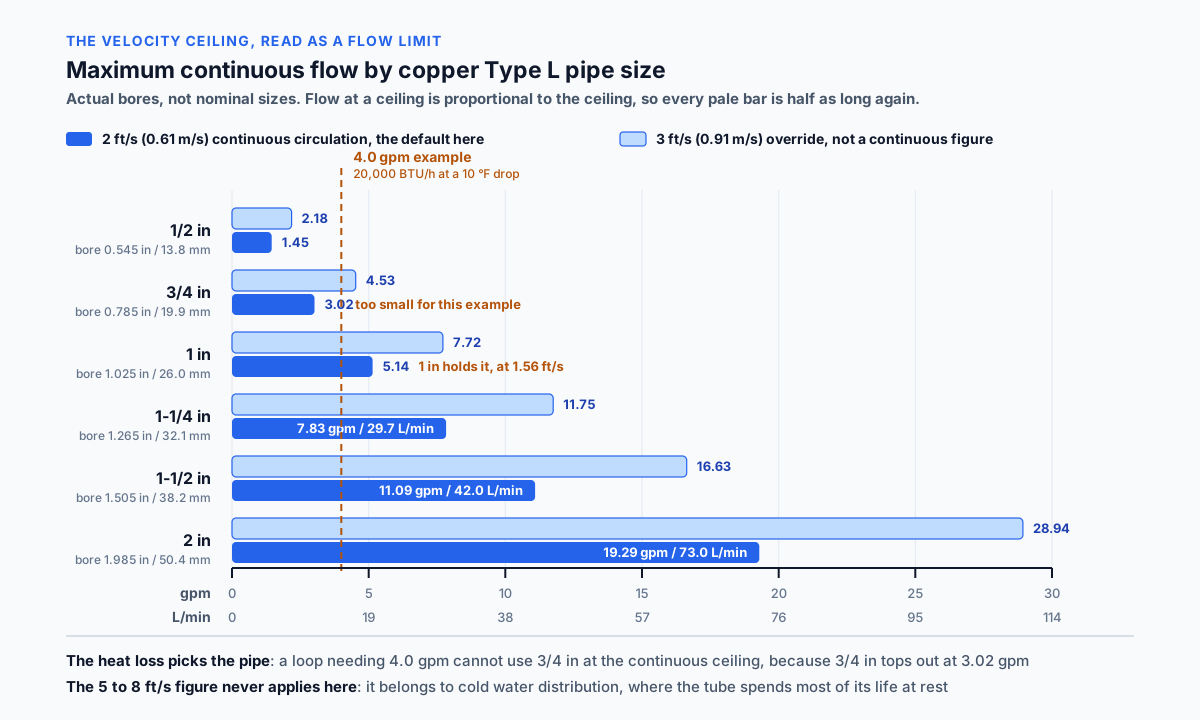
At 2 feet per second in Type L copper, using actual inside diameters rather than nominal sizes: a half inch line carries 1.45 gallons per minute, three quarter inch 3.02, one inch 5.14, one and a quarter inch 7.83, one and a half inch 11.09 and two inch 19.29. In litres per minute those are 5.5, 11.4, 19.5, 29.7, 42.0 and 73.0.
At the 3 feet per second override the same sizes carry 2.18, 4.53, 7.72, 11.75, 16.63 and 28.94 gallons per minute. Every figure is exactly half as much again, because the flow at a ceiling is directly proportional to the ceiling.
Read the other way, that table sizes the pipe. A loop needing 4 gallons per minute cannot use three quarter inch pipe at the 2 foot ceiling, because three quarter inch tops out at 3.02. One inch is the smallest size that holds it, and it runs at 1.56 feet per second with room to spare.
The bores behind those figures are 0.545, 0.785, 1.025, 1.265, 1.505 and 1.985 inches, which are 13.8, 19.9, 26.0, 32.1, 38.2 and 50.4 millimetres. They are not arbitrary: copper tube outside diameter is the nominal size plus one eighth of an inch, and the Type L wall of 0.040 to 0.070 inches comes off that twice. Velocity depends on the bore squared, so using a nominal 0.75 for three quarter inch instead of 0.785 reads about 10 percent low, and friction depends on the bore to a higher power still.
One point belongs to the next section and is worth flagging here. The size to check against this table is not automatically the return line. It is the narrowest pipe anywhere in the continuous recirculation path.
Controlling Segment Versus Return Pipe
Most guidance on recirculation velocity speaks in terms of the return line, and most of the time that is right. It is not always right, and when it is wrong the error is large.
The recirculation flow is the same through every segment of the continuous path. Water leaving the pump passes through the supply main, the branches that carry recirculation flow, and the return, and none of it disappears along the way. Velocity therefore depends only on the bore of each segment, and the segment that governs is the narrowest pipe carrying that flow.
In a purpose designed loop the return is usually the smallest pipe, which is why the shorthand works. But a supply main that necks down before the last fixture, with the recirculation flow continuing through it, governs instead. The ASPE presentation makes the same point from the design side, warning that smaller supply and return piping is assumed until the flow is determined and that it is not always three quarter inch.
The scale of the difference is not marginal. Take a loop carrying 4 gallons per minute. Through a three quarter inch return, bore 0.785 inches, it runs at 2.65 feet per second, which is over the 2 foot ceiling but inside a 3 foot one and looks tolerable. Through a half inch segment on the same loop, bore 0.545 inches, it runs at 5.50 feet per second, which is more than double the reported figure and outside every ceiling in circulation, including the 4 to 5 that applies to hot water below 140 F in ordinary intermittent service.
A calculator that asked for the return line would report 2.65, pass it against the looser ceiling, and say nothing about a segment eroding at 5.50.
This calculator therefore asks for the smallest pipe in the continuous recirculation path and says so in the field label rather than only in the helper text. A field called return pipe size gets filled with the return pipe size whatever the helper says.
Finding that segment is a drawing exercise rather than a calculation. Trace the path the recirculation flow takes from the pump discharge back to the pump suction, note every change of size along it, and use the smallest.
Oversized Recirculation Pump and Pinhole Leaks
On most pump pages an oversized pump wastes money. Here it destroys the piping, and it does so slowly enough that the connection is usually lost by the time the leaks appear.
The failure is erosion corrosion: a mechanically induced failure where fast moving water strips material from the inside of the tube. The Copper Development Association describes it as readily identifiable by the horseshoe shaped pitting throughout the inside of the tubes, which is its distinctive signature. Trade coverage describes the same damage as velocity channels, copper eroded away by high speed water.
Published guidance names high velocity from an oversized pump as the number one cause of pinhole leaks in recirculation pipes. The Copper Development Association names the same two causes from the design side: an undersized piping system or an oversized recirculating pump may cause high water velocity.
What makes it worse than a proportional penalty is that turbulence rises with the square of the flow. A pump delivering twice the required flow produces four times the turbulence. Three times the flow produces nine times. There is no conservative direction in oversizing here, only an accelerating one.
A published case shows what that costs. At a recently opened fifteen storey hotel near Lake Tahoe, a guest reported a small leak in a ceiling. Investigation found a pinhole in a copper pipe on the recirculating hot water system, then another, then another. By the time consulting engineers were involved, nearly every room showed water damage on walls or ceilings, and the recirculating system had to be repiped at a six figure cost, before counting lost revenue.
The remedy is named at source rather than inferred. The Copper Development Association states that installation of a smaller capacity pump, or a throttling bypass on the existing pump, should help in lowering the velocity of the water in the system. A larger pipe achieves the same thing from the other direction, and this calculator names both.
Water chemistry shifts the margin rather than the arithmetic. Chlorine in the supply is aggressive to piping as well as to bacteria, and chloramine, which combines chlorine with ammonia so the disinfectant lasts longer, stays corrosive for longer too. A system in aggressive water is designed below the ceiling rather than at it.
Pump Head and Duty Point
The head a recirculation pump must develop is the friction and pressure loss around the supply and return circuit. What goes into that figure, and how precise it is, are worth being clear about.
The starting point is the developed length of the circuit, measured from the pump to the farthest point and back. During design the actual route is often unknown, and a common allowance adds 50 to 100 percent to an estimated length to account for fittings. That allowance is scale dependent and it is worth saying so: in the published ASPE example the fittings add 29 feet to a 1,500 foot run and 22 feet to a 1,000 foot run, which is about 2 percent, not 50. The larger figures belong to a short circuit full of changes of direction, which is what a residential recirculation loop usually is.
The friction is then taken from an allowable uniform friction loss. Published design guidance gives 2 feet of head per 100 feet as a working value, with the author noting it can be any reasonable value that does not produce excessive velocities. A 200 foot circuit with a 50 percent fittings allowance is 300 equivalent feet, which at that value gives 6.0 feet of friction head, or 1.83 metres.
That number is a design allowance rather than a computed gradient, and the distinction matters. The designer chooses a uniform loss value and then selects pipe sizes that meet it. It is not a prediction of what a particular pipe will do at a particular flow: 4 gallons per minute through three quarter inch copper actually produces a Hazen-Williams gradient with C of 140 nearer 4.7 feet per 100 feet, more than twice the allowance. So the allowance is a target used to choose pipe size, not a post selection calculation for any arbitrary pipe.
Component losses are added to the friction head: balancing valves, thermostatic recirculation valves, check valves, isolation valves, strainers and the heater or storage vessel. Published guidance puts them on the return connections at the water heater, at the pump and at any thermostatic mixing valve cold water inlet. A duty point without them is preliminary, so this calculator lists what belongs there when none are entered rather than treating the friction head as the total.
The result of all that is a required duty point, expressed as a flow at a head. For the worked example above, 4.0 gallons per minute at 6.0 feet, or 9.0 feet with 3 feet of component losses.
What this calculator does not do is confirm a pump. Selecting a model means reading a manufacturer curve at that flow and head and checking that the pump sits on it comfortably rather than at the end of its range. The duty point is the requirement; the curve is the confirmation.
Insulation and the Heat Loss the Flow Comes From
Insulating a recirculation loop is usually presented as an energy measure. On this page it is a sizing input, because the flow is the heat loss divided by a constant and a temperature drop, and insulation is the largest lever anyone has on the heat loss.
The relationship is exact and needs no rule of thumb. The flow is directly proportional to the heat loss, so whatever insulation does to the heat loss it does to the required flow, one for one, and to the velocity with it. Halve the heat loss and you halve the flow, the velocity and the erosion exposure at the same time.
A range of about a quarter to a third of the uninsulated flow circulates as field guidance for what insulation achieves. It is not printed as a figure here, because it could not be confirmed in any of the sources this page cites, and a quantitative multiplier with no source behind it is exactly the kind of number that propagates into a pump selection and is never questioned again. What can be said with a source is the direction and the mechanism.
The figures that are published are per foot heat losses for insulated pipe. The ASPE example uses 8.90 BTU per hour per foot for 2 inch copper with 2 inch insulation, 7.59 for 1-1/2 inch with 2 inch insulation, 7.25 for 1 inch with 1-1/2 inch insulation and 6.33 for 3/4 inch return with 1-1/2 inch insulation. ASPE also states plainly that insulation reduces heat loss but does not eliminate it, which is why a well insulated loop still needs a pump.
The Copper Development Association arrives at insulation from a different direction and reaches the same place. It states that heating water above 140 F can accelerate the process of erosion corrosion, and that to avoid cold hot water concerns, insulation can be added to the hot water supply lines. In other words, insulation is the alternative to raising the temperature, and raising the temperature is what damages the pipe.
So insulation does two things on a recirculation system: it reduces the flow the pump has to move, and it removes the reason to run the loop hotter. Both reduce erosion. ASHRAE 90.1-2019 Addendum aq sets minimum insulation thicknesses for service water heating piping, so on most projects the question is how much rather than whether.
Treating it as a line item to be value engineered out at the end is therefore a decision to buy a larger pump and larger pipe, and to run them harder for twenty years.
Non-Ferrous Pump Body for Domestic Hot Water
A recirculation pump and a hydronic heating circulator can share a duty point and still not be interchangeable, and the difference is what the water does to the pump body.
A closed hydronic heating loop recirculates the same water indefinitely. That water gives up its dissolved oxygen early in the system's life and then behaves: it is treated, it is not replaced, and a cast iron pump body lasts in it for decades. Cast iron circulators are entirely standard in heating work for that reason.
A domestic hot water recirculation loop is not closed in the same sense. Every time a fixture opens, fresh water enters the system, and that water is oxygenated, chlorinated and continuously renewed. The ASPE presentation on domestic hot water recirculation puts the requirement without qualification: all domestic water pumps must be bronze or stainless steel fitted.
So the correct pump here has a bronze or stainless steel body. Fitting a cast iron circulator because the flow and head match is one of the more common errors when a heating contractor is asked to add a recirculation loop to a building, and the pump fails from the inside rather than from the duty.
The distinction also runs the other way. A bronze or stainless pump will work perfectly well on a closed hydronic loop; it simply costs more than the job requires. The substitution is only a problem in one direction.
This calculator states the requirement on every result rather than only when a pump type is entered, because the assumption that a circulator is a circulator is the default position for anyone coming from heating work.
Balancing Recirculation Branches
A recirculation calculation describes a loop where the flow goes where the design intends. Without balancing, it does not.
Published guidance on domestic hot water recirculation states that balancing valves must be sized for each branch and riser to provide the desired temperature drop. ASHRAE Standard 188 goes further and requires that all water systems be balanced and a balance report provided to the building owner, which makes this a documented deliverable rather than a commissioning courtesy.
The reason is that water takes the path of least resistance. On a system with several risers or branches returning to a common line, the shortest and least restrictive path takes most of the flow, and the longest path takes least. That is exactly backwards from what the design needs, because the far branch is the one the calculation was built for.
The consequence is two failures from one cause. The near branches run fast, which is an erosion problem: they may exceed the velocity ceiling even though the total system flow is correct. The far branch runs slow, which is a temperature problem: the water cools before it reaches the fixture, which is the condition the recirculation system exists to prevent.
Adding pump flow does not fix it. More flow makes the near branches faster without materially helping the far one, so an unbalanced system that is short of temperature at the end of the run tends to get a larger pump, which accelerates the erosion on the branches that were already fast.
Balancing valves, or thermostatic recirculation valves that modulate to a set return temperature, distribute the flow according to the design rather than according to the resistance. Manual valves are pressure dependent and hold a setting; thermostatic types adjust flow as temperatures move.
A single loop with no branches does not have this failure mode. Flow control still matters and the short circuit problem does not arise, which is why this calculator asks for the balancing status rather than issuing the same warning to every system.
Workmanship and Local Velocity
A design velocity inside the ceiling is a necessary condition and not a sufficient one. Several installation defects create local velocities far above the average, and no calculation sees them.
The Copper Development Association lists them directly.
Burrs left on the inside of the tube from unreamed ends cause interruption of smooth flow, resulting in localized high water velocity and cavitation. Immediately downstream of an unreamed tube end the local flow pressure is drastically reduced, allowing air bubbles entrained in the water to escape and scour the tube and fitting wall, creating pits that may eventually cause failure.
Protrusions into the flow stream do the same. Excessive lumps of solder or brazing material, or an improperly fabricated tee where the branch protrudes into the run pipe, interrupt smooth flow and produce the same localized high velocity and cavitation.
Numerous abrupt changes in direction have a cumulative effect, and the recommendation is specific: where structural conditions cause numerous directional changes, long radius fittings at 1.5 times the diameter should be used to minimize the interruption of laminar flow.
That last point lands squarely on recirculation systems, which by their nature run the length of a building and back and are full of turns.
Excessive amounts of dissolved gases, vapours or suspended solids in the water conveyed are named as a further factor: at high velocities these impinge on the metal surface and cause erosion corrosion.
None of this changes the number this calculator produces. What it changes is how much margin that number deserves. A loop designed at 1.8 feet per second with unreamed ends and short radius elbows can erode where a loop designed at the same figure with good workmanship does not, and the difference is invisible in the arithmetic.
Temperature, Water Chemistry and Legionella
Three conditions outside the pump calculation change how much velocity the copper will tolerate, and one of them pulls against a requirement from a different discipline entirely.
Temperature is the clearest. The Copper Development Association states that heating the water above 140 F can accelerate the process of erosion corrosion, and its velocity guidance reflects that directly: 4 to 5 feet per second for hot water below 140 F, and 2 to 3 above it. A published forensic account of a recirculation failure recommends designing these systems so that temperatures generally do not exceed 140 F, depending on local code requirements, with velocity no greater than 3 feet per second.
Water chemistry shifts the margin. Chlorine is added to water to kill bacteria and it is aggressive to piping as well; chloramine, which combines chlorine with ammonia to make the disinfectant last longer, stays corrosive for longer too. Dissolved gases and suspended solids impinge on the tube wall at high velocity and do the same. None of these changes the arithmetic; all of them argue for designing below the ceiling rather than at it.
The tension is with Legionella control, and it is not a small one. The favourable growth range for the bacteria is roughly 68 to 122 F, almost all die above 130 F, ASHRAE Guideline 12 recommends the circulating hot water system should not drop below 120 F, and water management practice stores and distributes at or above 140 F with a return temperature of at least 124 F. Every one of those figures pushes the loop temperature up. Copper erosion pushes it down, and the copper guidance changes ceiling precisely at 140 F. The two requirements meet at the same number and pull in opposite directions.
This calculator names that trade off and does not resolve it. Resolving it belongs to a water management plan under ASHRAE Standard 188, which considers the building type, the occupants, the risk criteria and the mitigation available, including thermostatic mixing valves at fixtures to deliver tempered water from a hotter loop.
The controls question sits in the same place. The 2021 IECC requires controls that automatically turn the pump off when the loop is at the desired temperature and there is no demand for hot water, while ASHRAE 188 does not recommend an aquastat to control a circulating pump. That conflict is a conversation with the authority having jurisdiction, and it is worth having before the pump is ordered.
What the calculator can do is make the cost of the decision visible. A loop run hotter for water safety is a loop that needs a lower velocity ceiling, which means either a lower flow or a larger controlling segment. That is a design consequence rather than an opinion.
What Is a Hot Water Recirculation Pump
A hot water recirculation pump keeps a loop of hot water moving so that hot water is available at a fixture without running the tap and waiting. Without one, the water sitting in a long supply run cools between uses and has to be flushed down the drain before hot water arrives.
The loop is a circuit rather than a supply. Hot water leaves the heater, travels the supply main, and a return line brings it back to the heater inlet, so the water in the pipe is continuously replaced with hot water from the source. The pump is what drives that circuit.
What makes sizing it different from every other pump on a plumbing job is that it serves no demand. When a tap opens, the water it delivers comes from the heater through the supply, exactly as it would without a recirculation system. The pump's only job is to replace the heat the pipe loses to the building while nobody is drawing anything.
That has three consequences that run against normal pump instinct. The flow follows from a heat loss rather than a demand. The head is friction only, because a closed loop has no net lift. And the pump must be small, because it runs continuously and a continuous high velocity erodes copper in a way that an occasional peak does not.
Most of the trouble on recirculation systems traces back to a pump that is larger than any of that requires.
Key Facts
- The recirculation flow is the system heat loss in BTU per hour divided by 500 times the design temperature drop in degrees Fahrenheit. A published ASPE presentation gives it in that form and it is described elsewhere as the ASPE verified formula.
- Ten degrees Fahrenheit is the common design temperature drop and five is used where tighter control is required. Neither is universally mandated. A larger drop reduces the flow and delivers cooler water at the far fixture.
- A loop losing 20,000 BTU per hour, which is 5,861 watts, needs 4.0 gallons per minute at a 10 degree drop, which is 15.14 litres per minute.
- A published residential worked example arrives at 1.9 gallons per minute at 5.2 feet of head. A published commercial example, a 3,100 foot loop at 10.3 gallons per minute, arrives at 31.5 feet.
- The Copper Development Association gives maximum velocities in copper tube of 5 to 8 feet per second for cold water, 4 to 5 for hot water below 140 F, and 2 to 3 for hot water above 140 F.
- Code commentary on limitation of velocity is stricter for this application: those figures are too great where the flow is continuous, as in recirculated hot water piping, and continuous hot water circulation should be limited to not more than 2 feet per second. An ASPE Pipeline article instructs designers to keep all hot water circulating systems below 2.
- Turbulence rises with the square of the flow, so a pump delivering twice the required flow produces four times the turbulence.
- Maximum continuous flow in Type L copper at 2 feet per second: 1.45 gallons per minute in half inch, 3.02 in three quarter inch, 5.14 in one inch, 7.83 in one and a quarter inch, 11.09 in one and a half inch and 19.29 in two inch.
- At the looser 3 feet per second figure the same sizes carry 2.18, 4.53, 7.72, 11.75, 16.63 and 28.94 gallons per minute, exactly half as much again in every case.
- Type L bores are 0.545, 0.785, 1.025, 1.265, 1.505 and 1.985 inches, which are 13.8, 19.9, 26.0, 32.1, 38.2 and 50.4 mm. Copper tube outside diameter is the nominal size plus one eighth of an inch and the Type L wall comes off that twice, which is why no bore equals its nominal size.
- Velocity depends on the bore squared, so a nominal 0.75 used in place of the 0.785 bore of three quarter inch tube reads about 10 percent low.
- The flow is the same in every segment of a loop, so the narrowest pipe carrying it governs the velocity. That is often the return line and it is not always: a 4 gallon per minute loop reads 2.65 feet per second in a three quarter inch return and 5.50 in a half inch segment.
- A published ASPE example carries 10.1 gallons per minute where the 3/4 inch return runs at 6.6 feet per second, and revises the 3/4 inch and 1 inch piping to 1-1/4 inch, which runs at 2.6. The larger pipe loses slightly more heat, so the flow rose to 10.3 gallons per minute while the pump head fell by more than 40 feet.
- Published per foot heat losses for insulated Type L copper: 8.90 BTU per hour per foot for 2 inch with 2 inch insulation, 7.59 for 1-1/2 inch with 2 inch insulation, 7.25 for 1 inch with 1-1/2 inch insulation and 6.33 for 3/4 inch with 1-1/2 inch insulation.
- The uniform friction allowance of 2 feet per 100 feet is a design target used to choose pipe size. The actual Hazen-Williams gradient with C of 140 at 4 gallons per minute in three quarter inch copper is nearer 4.7 feet per 100 feet.
- Legionella grows favourably between about 68 and 122 F and almost all die above 130 F, ASHRAE Guideline 12 recommends the circulating system not drop below 120 F, and practice stores and distributes at or above 140 F with a return of at least 124 F. Copper guidance drops its velocity ceiling at the same 140 F, so the two requirements meet at one number and pull opposite ways.
Applications
- An engineer sizing a recirculation loop for a hotel converts the pipe heat loss into a flow and finds the pump is far smaller than the building height would have suggested.
- A contractor replacing a failed circulator checks whether the original was oversized, because the pipe it fed has been leaking.
- A designer working out why a system started developing pinhole leaks finds the velocity in the return exceeds the continuous ceiling and traces it back to a pump chosen on a static head that was never there.
- A plumber weighing insulation against accepting the heat loss sees that the flow moves with the heat loss one for one, and therefore so do the pump and the pipe size.
- A facilities manager comparing a 140 F loop against a hotter one for water safety sees the erosion trade off stated rather than implied.
- A designer with a loop full of elbows finds that long radius fittings and properly reamed tube ends matter as much as the calculated velocity, because both create local high velocity that no design figure captures.
- A heating contractor asked to add a recirculation loop finds that the circulator they would normally reach for has the wrong body material for domestic water.
Example Calculations
Example 1. The flow comes from heat, not from fixtures
Given: a loop losing 20,000 BTU per hour, with a 10 degree Fahrenheit design temperature drop.
The flow is 20,000 divided by 500 times 10, which is 4.0 gallons per minute, or 15.14 litres per minute. At a 10 degree drop that is the same as dividing by 5000.
Result: 4.0 gallons per minute, and nothing in that calculation asked how many fixtures the building has. The same loop serving one bathroom and forty bathrooms needs the same recirculation flow, because the pipe loses the same heat either way.
Example 2. The building height that is not in the head
Given: a fifteen storey building with a recirculation loop, and a 200 foot circuit from the pump to the farthest point and back.
With a 50 percent fittings allowance the equivalent length is 300 feet. At a uniform friction allowance of 2 feet per 100 feet, the friction head is 6.0 feet, or 1.83 metres.
Result: about 6 feet of head, not 150. An operating recirculation loop is a closed circuit: the column returning from the top pushes down with the force the rising column resists, so the two cancel. Adding the building height here would specify a pump roughly twenty five times too large.
Example 3. The oversized pump eats the pipe
Given: the 4.0 gallons per minute from Example 1, through a three quarter inch Type L copper controlling segment with a bore of 0.785 inches.
The velocity is 0.4085 times 4.0 divided by 0.785 squared, which is 2.65 feet per second, or 0.81 metres per second.
Result: over the 2 feet per second continuous ceiling. The maximum this pipe can carry continuously is 3.02 gallons per minute, and the smallest pipe that holds the ceiling at 4.0 is one inch, which runs at 1.56 feet per second.
Both remedies are named at source. The Copper Development Association states that installation of a smaller capacity pump or a throttling bypass should help lower the velocity, and a larger pipe does the same from the other direction. Turbulence rises with the square of the flow, so twice the required flow produces four times the turbulence.
Example 4. The controlling segment is not always the return
Given: the same 4.0 gallon per minute loop, with a three quarter inch return line and a supply main that necks down to half inch before the last fixture, with the recirculation flow passing through it.
Through the three quarter inch return the velocity is 2.65 feet per second. Through the half inch segment, bore 0.545 inches, it is 5.50.
Result: the same loop reads 2.65 or 5.50 depending on which pipe is checked. A calculator asking for the return line would report 2.65, pass it against a 3 foot ceiling, and miss a segment running at more than double that figure.
Example 5. Insulation moves the flow one for one
Given: the 20,000 BTU per hour loop from Example 1, re-walked with the supply and return insulated so the heat loss comes out at 8,000 BTU per hour.
The flow is 8,000 divided by 500 times 10, which is 1.6 gallons per minute. In the same three quarter inch segment the velocity falls from 2.65 to 1.06 feet per second.
Result: a different design, not a cheaper version of the same one. The uninsulated loop needs a one inch controlling segment to hold the 2 foot ceiling; the insulated one is comfortable in three quarter inch. Note what this example does not do: it does not apply a factor to the flow. The heat loss was recalculated with the insulation in it, and the flow followed. That is the only honest route, because the flow is proportional to the heat loss and nothing else.
Example 6. The published revision case
Given: a published ASPE example carrying 10.1 gallons per minute at a 5 degree drop, with a 3/4 inch return and 1 inch supply, revised to 1-1/4 inch throughout.
The source reports 6.6 feet per second in the 3/4 inch pipe and 2.6 in the 1-1/4 inch. Computing from the Type L bores gives 6.70 and 2.58, which agrees to within the source's own rounding.
Result: the revision worked, and not quite in the way a velocity table alone would suggest. Enlarging the pipe increased the surface area and therefore the heat loss, so the required flow rose slightly, from 10.1 to 10.3 gallons per minute. The pump head still fell by more than 40 feet. The lesson is that pipe size and flow are not independent on a recirculation loop: the pipe is part of the heat loss that sets the flow.
Example 7. What the design figure does not capture
Given: a loop designed correctly at 1.8 feet per second, with unreamed tube ends and several short radius elbows.
Result: the calculated velocity is inside the ceiling and the pipe can still erode. Burrs interrupt smooth flow and cause localized high velocity and cavitation immediately downstream; protrusions from excess solder or a poorly fabricated tee do the same. Where a system has numerous abrupt changes in direction, long radius fittings at 1.5 times the diameter are recommended.
Example 8. The pump that is right for a heating system and wrong for this one
Given: a cast iron circulator, standard on a hydronic heating loop, proposed for a domestic hot water recirculation loop at the same duty.
Result: the wrong pump. A closed hydronic loop recirculates treated water that gives up its oxygen and settles. A domestic hot water system is continuously supplied with fresh, oxygenated water, so the pump body must be non ferrous. The duty point may be identical and the material is not interchangeable.
Example 9. The 3 foot per second override
Given: a loop at 2.58 feet per second, with the ceiling changed from 2 to 3.
Result: it passes the selected ceiling and the result says which ceiling that is and where it comes from. The 3 foot figure is the top of the Copper Development Association range for hot water above 140 F and the figure a published forensic account recommends, both of which describe hot water service rather than continuous circulation, and both code commentary and ASPE guidance place continuous circulation at not more than 2. Selecting it is a deliberate, less conservative choice rather than a default, and where the supply temperature is also above 140 F the two decisions compound.
Example 10. Component losses move the duty point
Given: the 6.0 feet of friction head from Example 2, with 3 feet added for balancing valves, a check valve and the heater.
Result: a duty point of 4.0 gallons per minute at 9.0 feet rather than 6.0, a 50 percent increase in the head from components alone. Until those are included the duty point is preliminary, which is why the calculator lists what belongs there when the field is left blank rather than presenting the friction head as the total.
Example 11. A timer does not relax the velocity check
Given: the same loop, run by a timer for eight hours a day instead of continuously.
Result: the annual run hours and the energy fall, and the velocity while the pump is running does not change. The erosion happens during the hours the pump is on, so the ceiling applies unchanged. Controls are an energy measure rather than a way to justify a larger pump, and the control strategy itself is contested: the 2021 IECC requires automatic pump shutoff, while ASHRAE 188 does not recommend an aquastat for the job.
Example 12. A plastic system is a different calculation
Given: PEX or CPVC recirculation piping.
Result: no copper ceiling is applied and no velocity verdict is issued. Plastic piping systems carry manufacturer specific velocity and temperature limits, and the erosion mechanism that governs copper does not transfer to them. The flow arithmetic is material independent, so the gallons per minute figure would be the same; what this page will not do is tell you whether that flow is acceptable in a pipe whose limits come from its manufacturer.
Standards & References
- Copper Development Association, Designing and Installing Copper Piping Systems The primary source for the velocity figures used on this page: 5 to 8 feet per second for cold water systems, 4 to 5 for hot water systems below 140 F, and 2 to 3 for hot water systems above 140 F. Also names an undersized piping system or an oversized recirculating pump as causes of high water velocity, names a smaller capacity pump or a throttling bypass on the existing pump as the corrective action, identifies horseshoe shaped pitting as the distinctive signature of erosion corrosion, describes unreamed tube ends and protrusions into the flow stream as causes of localized high velocity and cavitation, recommends long radius fittings at 1.5 times the diameter where a system has numerous abrupt changes in direction, and recommends adding insulation to hot water supply lines to avoid cold hot water concerns rather than heating above 140 F. Linked through the Internet Archive because the Copper Development Association restructured its website and the original address now returns a 404; the snapshot is from April 2026.
- ASPE Pipeline, Corrosion in Hot Water Recirculating Systems and Velocity Effects Instructs designers to design all hot water circulating systems to keep velocities below 2 feet per second, cites the Copper Tubing Institute at 2 to 3 feet per second for hot water recirculation pipe with a lower velocity advised on half inch lines because of burrs or imperfections from faulty workmanship, and names undersized distribution lines and oversized circulating pumps with no bypass among the causes of excessive velocity.
- Code Commentary on Limitation of Velocity The stricter figure this page defaults to. States that this velocity is too great for systems where the flow is continuous, as in the case of recirculated hot water piping, and that the continuous flow rate for hot water with modest chemical content should be limited to not more than 2 feet per second for such continuous systems.
- ASPE Dallas Fort Worth Chapter, Domestic Hot Water Recirculation Systems The source for the flow equation, the head and the system requirements. States that the circulating pump flow is a function of the heat loss over time of the piping system and unfired hot water storage tanks at an acceptable temperature drop when no fixtures are used, gives the equation as system heat loss in Btuh divided by 500 times the temperature drop in F, states that the pump head is determined from the piping system's friction and pressure loss with no static head and that static head should not be included because the calculation is for a closed system, that all domestic water pumps must be bronze or stainless steel fitted, that balancing valves must be sized for each branch and riser to provide the desired temperature drop, and that smaller supply and return piping is assumed until the flow is determined and it is not always 3/4 inch. Carries the worked example revised from 3/4 inch to 1-1/4 inch, the per foot heat losses for insulated Type L copper, the 31.5 foot pump head example, and the ASHRAE 188 balancing and aquastat positions.
- JMP Coblog, Domestic Hot Water Recirculation Part 4: Pump Sizing Example A published residential worked example arriving at a selection for 1.9 gallons per minute at 5.2 feet of head, with the calculation steps and the note that 1 gallon per minute conveys 5,000 BTU per hour at a 10 degree drop.
- PHCP Pros, Domestic Hot Water Circulation Design The source for the uniform friction allowance. Sets out choosing a value for the allowable uniform friction head loss in the circulation piping, with 2 feet of head per 100 feet given as the author's working value and the note that it can be any reasonable value that does not produce excessive velocities.
- Consulting-Specifying Engineer, Recirculating Hot Water Can Corrode Pipes The forensic account behind the 3 feet per second figure and the hotel case. A recently opened fifteen storey hotel near Lake Tahoe where a guest reported a ceiling leak, investigation found a pinhole in the recirculating hot water copper, and by the time consulting engineers were involved nearly every room showed water damage and the system had to be repiped at a six figure cost. Recommends that these systems be designed so hot water temperatures generally do not exceed 140 F, depending on local code requirements, and flow velocity is no greater than 3 feet per second.
- Contractor Magazine, Ruined by Recirc States that high velocity due to an oversized pump is the number one cause of pinhole leaks in recirculation pipes, describes the channels seen in eroded copper as velocity channels cut by high speed water, and covers the effect of chlorine and of chloramine, which it characterises as chlorine on steroids.
- Hixson, Hot Water Recirculation System Design Gives the flow formula as system heat loss in BTU per hour divided by 500 times the temperature drop in F and describes it as the ASPE verified formula, notes 10 degrees Fahrenheit as a common design assumption with 5 used where tighter control is required and neither universally mandated, covers balancing and the fact that water follows the path of least resistance, and sets out the Legionella requirements including a water management plan under ASHRAE Standard 188-2021 and the minimum piping insulation of ASHRAE 90.1-2019 Addendum aq.
- ASTM B88, Standard Specification for Seamless Copper Water Tube The dimensional source behind the bores used in the velocity calculation. Copper water tube outside diameter is the nominal size plus one eighth of an inch, and the Type L wall thicknesses of 0.040, 0.045, 0.050, 0.055, 0.060 and 0.070 inches for half inch through two inch give the inside diameters of 0.545, 0.785, 1.025, 1.265, 1.505 and 1.985 inches used here. Velocity depends on the bore squared, so the nominal size is never substituted for it.
Units
Flow is reported in gallons per minute and litres per minute, at 3.785411784 litres per gallon. A 4.0 gallon per minute loop is 15.14 litres per minute, and the maximum continuous flows of 1.45, 3.02, 5.14, 7.83, 11.09 and 19.29 gallons per minute are 5.5, 11.4, 19.5, 29.7, 42.0 and 73.0 litres per minute.
Heat loss is entered in BTU per hour or watts, at 0.29307107 watts per BTU per hour. A 20,000 BTU per hour loop is 5,861 watts.
Temperature drop is entered in Fahrenheit or Celsius degrees. A difference converts by dividing by 1.8 without the 32 degree offset, because a difference has no zero point to shift, so a 10 F drop is a 5.6 C drop rather than minus 12 C. That distinction matters here because the flow formula uses a difference rather than a level. The supply temperature is a level and does carry the offset, so 140 F is 60 C.
Velocity is reported in feet per second and metres per second at 0.3048. The 2 feet per second continuous ceiling is 0.61 metres per second and the 3 foot override is 0.91.
Head and length are reported in feet and metres at 0.3048, so 6.0 feet of head is 1.83 metres and 9.0 feet is 2.74. The uniform friction loss is a ratio, feet of head per 100 feet or metres per 100 metres, so the same number applies in both systems.
Diameters are reported in inches with millimetres alongside at 25.4. Type L bores of 0.545, 0.785, 1.025, 1.265, 1.505 and 1.985 inches are 13.8, 19.9, 26.0, 32.1, 38.2 and 50.4 mm. Nominal pipe sizes stay in inches in both systems, because that is how copper tube is specified and ordered, and the bore rather than the nominal size appears in every equation.
The internal unit selector governs the fields, labels, math, on-screen result and any exported result, and it takes priority over any site-wide unit switch. Switching converts the values you entered rather than reinterpreting them.
Limitations
- This calculator sizes the recirculation duty. It does not compute the loop heat loss, which is the input everything else derives from, and it does not accept an estimate of it in this version because the published per foot figures are not implemented. Inventing that number would propagate into the flow, the velocity verdict and the pump selection at once.
- It covers copper Type L only. PEX, CPVC and other plastic systems carry manufacturer specific velocity and temperature limits and the copper ceiling should not be applied to them.
- The velocity check uses the smallest pipe you identify in the continuous recirculation path. It cannot see a segment you do not tell it about, and a narrower segment elsewhere in the loop would govern instead.
- It produces a required duty point and does not confirm a pump. Matching a model means reading a manufacturer curve at that flow and head.
- Timers, aquastats and demand controls change the hours the pump runs and not the velocity while it is running, so they do not relax the velocity check. Which control strategy is correct is itself contested between the 2021 IECC and ASHRAE 188.
Common Mistakes to Avoid
- Checking the return line and calling it the velocity. The flow is identical in every segment of a loop, so the narrowest pipe governs. A three quarter inch return reading 2.65 feet per second can sit on a loop with a half inch segment running at 5.50.
- Using nominal size in the velocity calculation. A three quarter inch Type L tube has a bore of 0.785 inches, not 0.75, and velocity depends on the bore squared.
- Using the uniform friction allowance as proof that a selected pipe has that loss. The 2 feet per 100 feet value is a design allowance used to choose pipe size. It is not automatically the actual gradient of the pipe entered, which at 4 gallons per minute in three quarter inch copper is nearer 4.7.
- Applying a 50 percent fittings allowance to a long main. That figure suits a short branchy route. On a published 3,100 foot loop the fittings came to about 2 percent of the run.
Frequently Asked Questions
How do I size a hot water recirculation pump?
Does the pump have to lift water to the top floor?
What velocity should I design a recirculation line to?
Why does an oversized recirculation pump cause leaks?
Which pipe do I check the velocity in?
What temperature drop should I use?
Can I use a heating circulator on a domestic hot water loop?
Does insulating the pipe change the pump size?
Does the number of fixtures affect the recirculation flow?
Can I use 3 feet per second instead of 2?
Does a timer or aquastat let me use a higher velocity?
Does this calculator work for PEX or CPVC recirculation?
Does the calculator choose the pump model?
Frequently Used Together
Engineers often use these calculators in combination for complete project workflows:
Related Calculators
Explore similar calculators that might be useful for your project:
Plumbing Quick Reference — Keep It On Your Phone On Site
A 10-page field reference for catching pressure, velocity, slope, and pump-sizing mistakes before you order pipe, close a wall, or add a booster.
- Velocity limits, fixture pressure minimums, drain slope, and the 80 psi ceiling in one table
- Worked examples that show why a single pressure number gives four different answers
- Keep it on your phone, or print the two field-check pages
Free PDF. Calculators stay free. Unsubscribe anytime.
Calculate
This selector governs every field, label, result and export on this page, and it takes priority over the site header switch. Switching converts the values you entered rather than reinterpreting them, so 20,000 BTU/h becomes 5,861 W and returns to exactly 20,000 when you switch back. Nominal pipe sizes stay in inches in both systems, because that is how copper tube is specified and ordered, and the bore rather than the nominal size appears in every equation. A temperature drop converts by dividing by 1.8 without the 32 degree offset, because a difference has no zero point to shift.
The Design Objective
This is the first question because it decides which heat loss belongs in the flow. Where the criterion is the temperature arriving at the farthest fixture, the supply piping loss to that fixture is what published guidance uses, because the return leg is downstream of the fixture and its losses do not affect what arrives there. Where the criterion is a minimum held everywhere in the loop, or a minimum return temperature, the return losses are included and the temperature drop is reconsidered against that objective. A designer working to a return temperature target with a supply only heat loss will undersize the flow.
The estimate route is not implemented in this version and returns a state rather than a number. A real estimate needs published BTU per hour per foot figures by pipe size, insulation state and temperature difference, and the heat loss is the input the flow, the velocity verdict and the pump selection all derive from, so a figure invented from a rule of thumb would propagate into every one of them at once. The distinction stays visible because it matters, and the route names where to get the figure instead of guessing at it.
Ten degrees Fahrenheit, which is 5.6 Celsius degrees, is the common design assumption, and five is used where tighter temperature control is required. Neither is universally mandated. A larger drop needs less flow, which is easier on the pump and the pipe, and it delivers cooler water at the far fixture so the occupant runs the tap longer and draws more hot water. This is a temperature difference rather than a level, so it converts by dividing by 1.8 with no 32 degree offset.
The Piping
This version carries copper velocity guidance and copper Type L bores only. Another material returns an out of scope state with no velocity verdict, because PEX, CPVC and other plastic systems carry manufacturer specific velocity and temperature limits and the erosion mechanism that governs copper does not transfer to them.
Not the return line by default. The recirculation flow is the same through every segment of the loop, so the narrowest pipe carrying it governs the velocity. In many systems that is the return, and it is not always: where a supply main necks down before the last fixture and the recirculation flow passes through it, that segment governs instead. Finding it is a drawing exercise rather than a calculation. Trace the path from the pump discharge back to the pump suction, note every change of size, and use the smallest.
The Head (all optional)
Measured from the pump to the farthest point and back. Leave it blank and the page still returns the flow and the velocity verdict, and reports the head and the duty point as not evaluated rather than as met.
A design allowance for a route that is not yet drawn, not a measurement, and it is scale dependent. On a published example of a 3,100 foot loop the fittings added about 2 percent to each long run, nowhere near 50. The larger figures belong to a short loop full of changes of direction, which is where a recirculation circuit usually is. If you have walked the route and your length already carries the equivalent lengths, add nothing.
Defaults to 2 if left blank, which published design guidance gives as a working value. This is a target the designer selects pipe to meet rather than a gradient computed from the bore and the flow: at 4 gallons per minute in three quarter inch copper the actual Hazen-Williams gradient with C of 140 is nearer 4.7 feet per 100 feet, more than twice the allowance. The value is a ratio, so it reads the same in both unit systems.
Balancing valves, thermostatic recirculation valves, check valves, isolation valves, strainers and the heater or storage vessel. Published guidance puts these on the return connections at the water heater, at the pump and at any thermostatic mixing valve cold water inlet. Until they are included the duty point is preliminary, and the result says so rather than presenting the friction head as the total.
The Checks (all optional)
The 2 foot per second default comes from code commentary on limitation of velocity, which states the ordinary figures are too great where the flow is continuous, and from an ASPE Pipeline article that recommends designing all hot water circulating systems below 2. The 3 foot figure is the top of the Copper Development Association range for hot water above 140 F and the figure a published forensic account of a recirculation failure recommends. Selecting it is a deliberate, less conservative choice and the result says so. The 5 to 8 feet per second figure familiar from cold water distribution is never applied on this page.
Used for the temperature caution only. Heating water above 140 F accelerates erosion corrosion, which is why the copper guidance drops from 4 to 5 feet per second below that figure to 2 to 3 above it. This is a temperature level rather than a difference, so it converts with the 32 degree offset.
Without balancing, the flow takes the path of least resistance and the short circuits take most of it, so the near branches run fast and the far branch, the one the design was built for, runs slow. That is an erosion problem and a temperature problem from one cause. A single loop with no branches does not have that failure mode, so the result distinguishes the two rather than issuing the same warning to both.
The flow is directly proportional to the heat loss, so whatever insulation does to the heat loss it does to the flow and to the velocity, one for one. That makes it a sizing input rather than an efficiency measure. The effect belongs inside the heat loss figure you enter rather than as a factor applied to the answer.