CPVC Pipe Sizing Calculator — CTS SDR 11 Bore and Temperature Derating
On this page
Calculate
This selector governs every field, label, result and export on this page, and it takes priority over the site header switch. Switching converts the values you entered rather than reinterpreting them, so 140 F becomes 60 C and returns to exactly 140 F when you switch back. Nominal pipe sizes stay in inches in both systems, because that is how CPVC is specified and ordered.
What the Pipe Carries
This question comes first because three of the six answers stop the calculation rather than adjusting it. Compressed air or gas is not permitted at all, and the reason is the failure mode rather than the rating. Fire sprinkler CPVC and CPVC DWV are different products under different rules, and a potable water figure does not transfer to either. An industrial or other non potable liquid puts chemical compatibility ahead of every pressure and temperature figure.
The Pipe
A nominal size on its own does not describe CPVC pipe. The same figure exists in more than one family with different outside diameters, different walls, different bores and different pressure ratings. In this version only CTS SDR 11 returns figures; the IPS options are listed because the distinction matters and they return a not implemented state rather than a CTS figure borrowed for another family.
The set published for CTS SDR 11, which is the range ASTM D2846 covers for hot and cold water distribution. Nominal sizes are trade designations rather than measurements of anything on the pipe, which is why the calculator looks up the published bore for each one before any equation uses it. Nominal sizes stay in inches in both unit systems.
Use the hottest the line will see in normal service, not the average. For domestic hot water use the storage or recirculation temperature, or the hottest continuous pipe temperature, rather than the mixed delivery temperature at a fixture, because the pipe sees the hotter figure continuously. The published derating table runs from 73 F to 180 F and no rating is returned above it.
Pressure, Flow and Lengths (all optional)
The highest sustained pressure expected at this location, including booster and pressure reducing valve settings and closed system expansion where applicable. Without it the calculator returns the rating figures and no verdict. Transient surge and water hammer are not evaluated here.
For velocity in the published bore and for friction. The flow comes from the water pipe sizing calculation rather than from this page, which never converts fixture units or a demand into a flow or a diameter.
Optional, and named as your own criterion when it is used. No universal velocity limit for CPVC was verified, so this page applies none of its own: without a limit the velocity is reported and no pass or fail is issued. Manufacturer data for a specific product or a project specification is where a legitimate limit comes from.
The length along the flow path including fitting equivalents, used for friction only. This is a different quantity from the straight run below and neither substitutes for the other.
The straight length between anchors or changes of direction, used for thermal movement only. A pipe with three offsets in it has a developed length that includes all of them and a set of shorter straight runs that each move independently, so using the developed length here overstates the growth of any one segment.
The temperature of the pipe when it was installed and the joints were made. The temperature change is the operating temperature minus this figure and it carries a sign, so a line installed warm and run cold contracts and pulls on its joints. Without it the movement is reported as not evaluated and no default is assumed.
Selecting copper returns the bore, the area, the velocity and the friction side by side. Both bore sets are read from published dimensional tables, CPVC to ASTM D2846 and copper Type L to ASTM B88, which is what the comparison was waiting for: two computed bores would have carried two errors pointing the same way. The movement comparison against copper is separate and is always shown when the movement is evaluated.
Overview
The pressure rating printed on CPVC is the rating at 73 F, and a hot water line is not at 73 F. The same tube rated 400 psi cold holds 200 psi at 140 F and 100 psi at 180 F. Nothing about the pipe changed; the number that describes it did. That is the first of three reasons a diameter is a complete answer in copper and half an answer in CPVC. The second is the bore, which is narrower than copper of the same nominal size. The third is movement, which runs about four times the copper figure and is measured in inches rather than tolerances.
What to Look at First
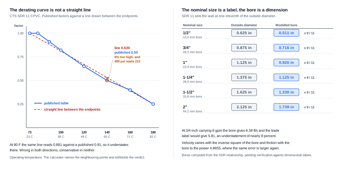
The rating at your temperature, not the rating on the pipe. The 400 psi figure printed along CPVC tubing is the rating at 73 F, and a hot water line is not at 73 F. The same tube holds 200 psi at 140 F and 100 psi at 180 F, so the useful line on the result is the derated one and the pair is always shown together. If your operating temperature is not one of the eight published points, the calculator names the points it sits between and withholds the verdict rather than interpolating, because the curve between them is not a straight line.
How to Use This Calculator
Say what the pipe carries. Potable hot and cold water, or cold water only, are the cases this page answers. Compressed air or gas, fire sprinkler CPVC, CPVC DWV and industrial liquids each stop the calculation, because they are different products or different rules and a potable water figure does not transfer to them.
Choose the dimension system and wall before the size. CTS SDR 11 to ASTM D2846 and IPS Schedule 40 or 80 to ASTM F441 are different pipe under the same nominal number. If you select IPS in this version, the calculator explains why the family matters and does not return CTS based numbers in its place.
Enter the nominal size. The calculator looks the published bore up for it and tells you which basis it used, because the bore is what appears in every equation below and the nominal size is a trade label.
Enter the maximum operating temperature. Use the hottest the line sees in normal service. On domestic hot water that is the storage or recirculation temperature, not the mixed temperature delivered at a fixture, because the pipe sees the hotter figure continuously.
Add the maximum operating pressure if you want a verdict rather than a rating. Include booster and pressure reducing valve settings and closed system expansion. Surge and water hammer are not evaluated here.
Add a design flow for velocity and friction, a project velocity limit if your specification sets one, and the two lengths if you want friction and movement. The hydraulic developed length and the straight run between anchors are different quantities and neither substitutes for the other.
Add the installed temperature to get thermal movement. Without it the movement is reported as not evaluated rather than assumed from a default.
Only the application, the family and wall, the nominal size and the maximum operating temperature are required. Every other field is optional and none of them block Calculate. What is left blank is reported as its own state rather than as a pass, so a missing operating pressure returns the rating without a verdict rather than a green result.
Inputs & Outputs
Inputs
Outputs
CPVC Pipe Sizing Formula
Four short calculations. The pressure rating is not among them, because it is a table lookup rather than an equation and it is covered in its own section below.
INPUTS
- application: what the pipe carries. Required, and three answers stop the calculation.
- family and wall: CTS SDR 11, or IPS Schedule 40 or 80. Required, and not assumed.
- nominal size: from the set published for the chosen family. Required.
- operating temperature: the hottest the line sees in normal service. Required.
- operating pressure: for the rating verdict. Optional.
- design flow, project velocity limit: for velocity. Optional.
- hydraulic developed length: for friction. Optional.
- straight run length, installed temperature: for movement. Optional.
Published bore, CTS SDR 11
bore_in = published average inside diameter
        = 0.469, 0.695, 0.901, 1.105,
          1.309, 1.716 in
A table lookup rather than an equation. The bores are read from manufacturer dimensional tables published to ASTM D2846 and cross-checked between two of them. A 3/4 inch CTS tube has an outside diameter of 0.875 inch, a published minimum wall of 0.080 inch and a published average bore of 0.695 inch, or 17.7 mm.
SDR 11 taken as a ratio would give the wall as one eleventh of the outside diameter and the bore as nine elevenths of it, which is 0.716 inch at 3/4 inch. That is close from 3/4 inch up and wrong at 1/2 inch, where the standard sets a wall floor of 0.068 inch instead of following the ratio down. The ratio is reported as a cross-check and is never the figure used.
Velocity in the published bore
velocity_fps = 0.4085 x gpm / bore_in ^ 2
The bore, not the nominal size. Velocity varies with the inverse square of it, so at 8 gallons per minute a 3/4 inch tube reads 6.77 feet per second on the bore and 5.81 on the trade label.
Temperature change
dT_F = operating_temp_F - installed_temp_F
Positive is expansion and negative is contraction. A line installed warm and run cold shortens, and no installed temperature is assumed, because a default would hide the direction as well as the magnitude.
Thermal movement
dL_in = 12 x e x L_ft x dT_F
The coefficient e is 3.4 times ten to the minus five inches per inch per degree Fahrenheit for CPVC, against about 9.2 times ten to the minus six for copper. The length is the straight run between anchors, never the developed length.
Friction, Hazen-Williams
ft_per_100 = 0.2083 x (100 / C) ^ 1.852
             x Q ^ 1.852 / bore_in ^ 4.8655
C is 150 for CPVC against about 130 to 140 for copper, so CPVC loses less to friction at a given bore. At the same nominal size it loses more, because its bore is narrower and the bore exponent of 4.8655 outweighs the roughness exponent of 1.852. The length here is the hydraulic developed length including fitting equivalents.
Unit conversions
mm    = in  x 25.4
kPa   = psi x 6.895
L/min = gpm x 3.785411784
A temperature difference in Fahrenheit divided by 1.8 gives the difference in Celsius, without the 32 degree offset, because a difference has no zero point to shift. Nominal pipe sizes stay in inches in both systems.
The remaining rules are conditions rather than equations: the family and wall selection, the pressure rating lookup, the absence of uprating below 73 F, the requirement that movement be absorbed, the support spacing requirement, and the chemical and compressed gas restrictions.
CPVC Pressure Rating and Temperature Derating
This is the single most important table on the page, and it is one table read two ways. The factor column tells you how much of the rating survives; the rating column tells you what is left.
For CTS SDR 11 CPVC the published points are:
At 73 F, factor 1.00, rating 400 psi, which is 2,758 kPa.
At 80 F, factor 1.00, rating 400 psi.
At 90 F, factor 0.91, rating 360 psi, which is 2,482 kPa.
At 100 F, factor 0.82, rating 325 psi, which is 2,241 kPa.
At 120 F, factor 0.65, rating 260 psi, which is 1,793 kPa.
At 140 F, factor 0.50, rating 200 psi, which is 1,379 kPa.
At 160 F, factor 0.40, rating 160 psi, which is 1,103 kPa.
At 180 F, factor 0.25, rating 100 psi, which is 690 kPa.
In Celsius those temperatures are 22.8, 26.7, 32.2, 37.8, 48.9, 60.0, 71.1 and 82.2.
Four things about this table decide how it should be used.
The rating holds flat from 73 F to 80 F. The first reduction appears at 90 F, so a cold water line in a warm plenum loses nothing.
The rating is not always the factor multiplied by 400. At 90 F, 400 times 0.91 is 364 and the table publishes 360. At 100 F, 400 times 0.82 is 328 and the table publishes 325. Two rows are rounded, so the published rating is the figure to use rather than a recomputed product.
The curve between the points is not a straight line, which matters more than it sounds. Draw a line from 1.00 at 73 F to 0.25 at 180 F and it gives 0.530 at 140 F where the published factor is 0.50. That overstates the rating by about 6 percent, in the unsafe direction, in the middle of the domestic hot water range. At 90 F the same line gives 0.881 against a published 0.91, so it understates there. A linear fit is wrong in both directions and is not conservative in either.
And the derating applies to a rating that already carries its design factor. The published figure includes a design factor of 0.5, and the temperature derating multiplies that published figure. Nothing further is added by the user, and a second margin applied on top will oversize the wall for no benefit.
One consequence for anything not on the list. If the operating temperature is 135 F, it is not a published point. The nearest published points are 120 F at 0.65 and 140 F at 0.50. This calculator names those points and withholds the pressure verdict rather than interpolating between them, because the arithmetic above shows that interpolation on this curve is not safe. The manufacturer's table for the specific product is the place to get an intermediate figure.
CTS Versus IPS CPVC Pipe
A nominal size is a complete specification in copper and is not one in CPVC, because the same number describes more than one pipe.
CTS is copper tube size, to ASTM D2846, in SDR 11. It shares the outside diameter of copper tube of the same nominal size and runs from 1/2 inch to 2 inch. This is the tube used for most residential and light commercial hot and cold water distribution, and it is what most people mean when they say CPVC pipe in a plumbing context.
IPS is iron pipe size, to ASTM F441, in Schedule 40 or Schedule 80. It uses a different outside diameter and a different wall, so a nominally identical pipe has a different bore and a different pressure rating. IPS covers the larger sizes and industrial work, and ASTM F442 covers SDR pipe in the same family.
The practical consequence is that a drawing calling for 1 inch CPVC has not specified a pipe. The outside diameter differs, the wall differs, the bore differs, the fittings differ, and the pressure rating differs. Two contractors reading the same note can order pipe that will not join.
It also means a rating cannot travel between families. The 400 psi at 73 F figure quoted throughout this page belongs to CTS SDR 11. Applying it to an IPS Schedule 40 pipe because the nominal size matches is the same error as reading a copper rating off a plastic datasheet.
This version of the calculator computes CTS SDR 11 only. IPS Schedule 40 and Schedule 80 remain in the family list, and selecting one returns an explanation rather than a number. That is deliberate: removing the option would hide the distinction, and the distinction is the point. A user who did not know the families differ learns it from the state rather than from an absence.
CPVC Bore Versus Nominal Size
The nominal size is a trade designation. The bore is a dimension, and only the second one appears in a calculation.
The bores used here are read from manufacturer dimensional tables published to ASTM D2846, and they were cross-checked between two of them before being used. Working through the CTS sizes: a 1/2 inch tube has an outside diameter of 0.625 inch and a published average bore of 0.469 inch, or 11.9 mm. A 3/4 inch tube is 0.875 inch outside and 0.695 inch bore, or 17.7 mm. A 1 inch tube is 1.125 inch outside and 0.901 inch bore. At 1-1/4 inch it is 1.375 and 1.105. At 1-1/2 inch, 1.625 and 1.309. At 2 inch, 2.125 and 1.716.
Notice that at every size the bore is smaller than the nominal figure, and at some sizes it is smaller than the next size down's nominal. A 1-1/4 inch CTS tube has a bore of 1.105 inch, narrower than the outside diameter of a 1 inch tube.
That gap does real work in two places. Velocity varies with the inverse square of the bore, so using the nominal figure understates it. At 8 gallons per minute through a 3/4 inch tube the published bore gives about 6.77 feet per second and the nominal figure gives about 5.81, an understatement of 14 percent. Friction varies with the bore to the power 4.8655, where the same error is larger again.
Why the published table and not the SDR ratio. SDR 11 defines the wall as one eleventh of the outside diameter, so it is tempting to take the bore as nine elevenths of it and stop there. That works from 3/4 inch up, where the published minimum wall lands within half a percent of the ratio. It fails at 1/2 inch, where the published minimum wall is 0.068 inch against an OD/11 of 0.0568 inch, twenty percent thicker, because the standard sets a wall floor at the small end rather than following the ratio down. The ratio returns 0.511 inch at 1/2 inch where the published average is 0.469 inch, which understates velocity by 19 percent and friction by 52 percent on the most common size in the range, and it understates in the unsafe direction.
There are two published bores rather than one, and the distinction matters. The minimum wall is a manufacturing floor, so the bore it implies is the widest the pipe is allowed to be: 0.489 inch at 1/2 inch, 0.715 at 3/4. The published average bore sits a constant 0.020 inch below that across the range, which is the average wall running thicker than the minimum. This calculator uses the average, because it is what a length of pipe actually runs at and it is the column the manufacturer's own friction and velocity tables are built on. The result reports both, so the width of the band is visible rather than hidden inside a single figure.
CPVC Velocity and Friction
Once the bore is known the hydraulics are ordinary arithmetic, with one deliberate omission.
Velocity is 0.4085 times the flow in gallons per minute divided by the bore in inches squared. At 8 gallons per minute through a 3/4 inch CTS tube with a published bore of 0.695 inch, that is about 6.77 feet per second, or 2.06 metres per second.
Friction uses Hazen-Williams with a roughness coefficient of 150 for CPVC, against about 130 to 140 for copper. CPVC is smoother, so it loses less head over the same length at the same bore.
The omission is a velocity limit. This page does not apply one, because no universal velocity limit for CPVC was verified. Manufacturer data may set a limit for a specific product and a project specification may set its own, and either is a legitimate criterion. What would not be legitimate is a limit invented here and presented as a property of the material, so the calculator reports the velocity and issues a verdict only against a limit you supply, naming it as your criterion.
That brings up the substitution question, which is where the two material properties collide.
Swapping copper for CPVC at the same nominal size changes the hydraulics in two opposing directions. The CPVC bore is narrower, because the CTS outside diameter is shared with copper while the CPVC wall is thicker, so the same flow runs faster. And the CPVC surface is smoother, so the friction coefficient is better. One effect pushes velocity up and the other pushes head loss down.
Which one dominates is an arithmetic question rather than a matter of judgement, and the answer needs both bores as published figures rather than as estimates. It has them now.
Both bore sets are now published figures, so the calculator computes the comparison rather than describing it. Select copper Type L and it returns the two bores, the difference in flow area, the difference in velocity at your flow, and the difference in friction, at the nominal size you chose.
The result overturns the assumption the smoothness argument usually leads to. At 3/4 inch the CPVC bore of 0.695 inch against copper Type L at 0.785 inch is 22 percent less flow area, so the same flow runs 28 percent faster. On friction, the better roughness coefficient of 150 against about 130 to 140 pulls head loss down by 12 to 23 percent on its own, but the narrower bore multiplies it by 1.8, because the bore carries an exponent of 4.8655 against the roughness term's 1.852. The two do not cancel and they are not close: CPVC loses roughly 39 to 59 percent more head than copper Type L at the same nominal size and the same flow. That pattern holds at every size in the CTS range, widening to 59 to 83 percent at 1/2 inch.
So the substitution moves both hydraulic figures the wrong way at once. A branch sitting comfortably inside a velocity limit in copper can cross it in CPVC at the same nominal size, and the pressure drop over the run rises at the same time rather than offsetting it. None of that makes CPVC the wrong material, which turns on rating, corrosion, cost and temperature rather than on head loss. It makes the diameter something that has to be recomputed rather than carried across.
CPVC Thermal Expansion
This is the largest single difference between CPVC and metal pipe, and it is measured in inches rather than in tolerances.
The coefficient of linear expansion for CPVC is about 3.4 times ten to the minus five inches per inch per degree Fahrenheit. Copper is about 9.2 times ten to the minus six. CPVC therefore moves roughly four times as far for the same run and the same temperature change. Manufacturer literature also publishes 3.2 times ten to the minus five for some compounds, a difference of about six percent on the result, so the figure used should be named and the manufacturer value used for final design.
Manufacturer guidance states it in a form worth remembering: a 25 F change produces about 1 inch of movement in a 100 foot straight run.
The movement is 12 times the coefficient, times the run in feet, times the temperature change in degrees Fahrenheit. A 60 foot run installed at 70 F and operating at 140 F moves about 1.71 inches, or 43.5 mm. The same run in copper moves about 0.46 inches, or 11.8 mm.
Two things about that calculation are easy to get wrong.
The length is the straight run between anchors or changes of direction, not the hydraulic developed length used for friction. A pipe with three offsets in it has a developed length that includes all of them and a set of shorter straight runs that each move independently. Using the developed length overstates the movement of any one segment.
And the temperature change is the operating temperature minus the installed temperature, which carries a sign. A cold water line installed at 70 F in a warm building and running at 50 F has a change of minus 20 F and contracts by about 0.49 inches over 60 feet. Contraction pulls on joints where expansion pushes on them, and a design that only considered growth has provided for the wrong direction.
The movement has to be absorbed by an expansion loop, an offset or a change of direction. Supports should restrict lateral movement and direct the axial movement into the loop, and hangers and guides belong in the loop or at the change of direction rather than clamped across the middle of a run that has to move. A hanger there either restrains the pipe, which loads the joints, or lets it buckle.
This page reports the movement and states that it must be absorbed. It does not dimension the loop, because loop and guide geometry depend on the modulus at temperature and belong to the manufacturer's engineering data. The site does carry a pipe expansion loop sizing calculator, which solves the guided cantilever leg length for a given movement and allowable stress range. Confirm before relying on it that it covers CPVC at your operating temperature rather than metal pipe alone: its material list is carbon steel, stainless steel and copper, and a leg length derived from a metal modulus does not transfer to a thermoplastic that loses stiffness as it warms.
CPVC Support Spacing at Temperature
Support spacing for CPVC is not a single number, and the reason is the same property that drives the pressure derating.
Thermoplastics soften as they warm. A CPVC line at 180 F is less stiff than the same line at 73 F, so it sags further between the same supports. Maximum support spacing therefore tightens as the operating temperature rises, and it also varies with pipe size, because a larger pipe carries more weight of water per foot while gaining stiffness at a different rate.
The practical consequence is one of the more common field errors on hot water work. A hanger schedule taken from a cold water table, or carried across from copper practice, will leave a hot CPVC line under-supported. The pipe does not fail; it sags between hangers, which puts a bend into every joint and pools water at the low points.
Spacing also interacts with the expansion question. Supports on a run that has to move are not there only to carry weight: they restrict lateral movement and direct the axial movement into the loop or offset. A support added simply to close a sag can defeat the expansion arrangement if it clamps rather than guides.
This calculator does not print a spacing figure. The published table by size and temperature has not been obtained, and printing a number from a generic hanger schedule or from memory would be worse than printing nothing, because a spacing figure looks authoritative and a wrong one produces exactly the sag it was meant to prevent. The page states the requirement and the direction of the relationship and points at the manufacturer table, and the figures will be added when that table is in hand. The site does carry a pipe support spacing calculator, which solves the maximum span from bending stress and deflection. Confirm before relying on it that it covers CPVC at your operating temperature rather than metal pipe alone: its material list is carbon steel, stainless steel and copper, and a span computed from a metal modulus will be too long for CPVC, and longer still as the line runs hot.
Where CPVC Cannot Be Used
Some of the answers on this page end the calculation rather than adjusting it, and they are worth knowing before a material is specified.
Compressed air and gas. CPVC is not permitted for the distribution of compressed air or gas, and manufacturer literature allows oil free air handling only to a low pressure limit. The reason is the failure mode rather than the rating. A water line that fails leaks, because water is nearly incompressible and there is no stored energy to release. A thermoplastic line carrying a compressed gas stores energy along its entire length, and when it fails it fails by shattering. This is a manufacturer restriction with a physical reason behind it rather than a code citation, and it is the one answer on this page that stops the calculation on safety grounds.
Fire sprinkler service. CPVC sprinkler pipe exists and is a separately listed system with its own approvals, its own sizing rules and its own fittings and cements. It is not the same product as potable water distribution CPVC and a rating or bore from this page does not transfer to it.
Drain, waste and vent. CPVC DWV is a non pressure product under different standards. Nothing on this page applies to it.
Industrial and other non potable liquids. Chemical compatibility governs before any pressure, temperature, bore or friction figure is worth computing. CPVC is incompatible with petroleum based products, aromatic hydrocarbons and chlorinated solvents, and the fluid has to be checked against the manufacturer's chemical resistance data before the pipe is considered at all.
That incompatibility list reaches beyond the fluid inside the pipe, which is the part most often missed. Thread sealants and pipe dope, fire stopping materials, some insulation, and cutting oils left on a surface can all attack CPVC from the outside. A system correctly specified for its contents can still fail because of what was put on it during installation.
CPVC Calculator Versus Water Pipe Sizing
These are two different calculations and running them in the wrong order wastes the first one.
Water pipe sizing answers what diameter carries the flow. It starts from fixture units, converts them to a design flow, and works down to a diameter under velocity and friction criteria. It is material aware only to the extent of a roughness coefficient, and it applies to copper, CPVC, PEX or anything else.
This page answers whether CPVC can be that diameter, and what changes when it is. It takes the size as given and returns the family, the wall, the published bore, the pressure rating at the operating temperature, the velocity the real bore produces, and the movement the run will make.
Neither substitutes for the other. Running this page without a diameter leaves you nothing to qualify. Running the sizing page and stopping there leaves a nominal size that does not yet describe a CPVC pipe, a rating that has not been derated for the water temperature, and a run whose movement has not been considered.
The order is therefore: size it there, qualify it here. In practice the second step sometimes sends you back to the first, because a diameter that worked in copper can produce a velocity in CPVC that the project will not accept, and that is a sizing decision rather than a material one.
This page will not choose a diameter under any circumstances. It does not take fixture units, it has no demand builder, and it does not convert a flow into a size. That boundary is deliberate, because two calculators answering the same question with slightly different assumptions is worse than one answering it well.
What is CPVC Pipe Sizing
CPVC is chlorinated polyvinyl chloride, a thermoplastic used for hot and cold potable water distribution where copper is expensive or where the water chemistry attacks it. It resists chlorine, chloramines and pH variation, and it does not suffer the copper ion catalysed oxidation that affects some other plastics.
Sizing it is not the same exercise as sizing copper, because a CPVC pipe carries more variables than a diameter.
It comes in two families, CTS in SDR 11 and IPS in Schedule 40 or 80, and the same nominal figure on a drawing can mean either.
Its strength depends on temperature in a way metal's does not. Thermoplastics lose strength as they warm, so a CPVC pressure rating is meaningful only alongside a temperature, and the published figure is at 73 F.
And it moves, at around four times the rate of copper, so a straight run in hot water service has to be designed with somewhere for the movement to go.
Sizing CPVC therefore means qualifying a diameter rather than choosing one: confirming the family and wall, working out the real bore, derating the pressure rating for the operating temperature, checking the velocity the real bore produces, and providing for the movement.
Key Facts
- CPVC tubing in CTS SDR 11 to ASTM D2846 is rated 400 psi at 73 F, which is 2,758 kPa at 23 C, and 100 psi at 180 F, which is 690 kPa at 82 C.
- The derating factors for CTS CPVC are 1.00 at 73 F and at 80 F, 0.91 at 90 F, 0.82 at 100 F, 0.65 at 120 F, 0.50 at 140 F, 0.40 at 160 F and 0.25 at 180 F.
- The corresponding published ratings are 400, 400, 360, 325, 260, 200, 160 and 100 psi. In kilopascals those are 2,758, 2,758, 2,482, 2,241, 1,793, 1,379, 1,103 and 690.
- The rating holds flat from 73 F to 80 F. The first reduction appears at 90 F.
- The derating factor is the same for all pipe sizes.
- The published pressure rating already includes the design factor of 0.5. Temperature derating is applied to that published rating, not to an unfactored figure.
- There are no uprating factors below 73 F. Cold water does not raise the rating, and the 73 F figure is a ceiling rather than a midpoint.
- The curve between the published points is not a straight line. Interpolating linearly between 73 F and 180 F overstates the factor at 140 F by about 6 percent and understates it at 90 F by about 3 percent.
- Two rows are rounded rather than computed: 400 times 0.91 is 364 where the table gives 360, and 400 times 0.82 is 328 where the table gives 325.
- CTS SDR 11 CPVC bores are read from published dimensional tables rather than from the SDR ratio. A 3/4 inch tube has an outside diameter of 0.875 inch, a published minimum wall of 0.080 inch and a published average bore of 0.695 inch, or 17.7 mm.
- Published CTS average bores across the range: 0.469 inch at 1/2 inch, 0.695 at 3/4, 0.901 at 1, 1.105 at 1-1/4, 1.309 at 1-1/2 and 1.716 at 2 inch. Every one is narrower than the SDR ratio alone would suggest, and at 1/2 inch it is narrower by 9 percent.
- Using the nominal size instead of the bore understates the velocity by nearly 9 percent at 3/4 inch, and friction by more, because friction varies with the bore to the power 4.8655.
- CPVC in CTS has a narrower bore than copper of the same nominal size, because the copper tube outside diameter is shared and the CPVC wall is thicker. The same flow therefore runs faster in CPVC.
- CPVC is smoother than copper, with a Hazen-Williams roughness coefficient of about 150 against 130 to 140, so it loses less to friction at a given bore. That effect runs against the narrower bore rather than adding to it.
- The coefficient of linear expansion for CPVC is about 3.4 times ten to the minus five inches per inch per degree Fahrenheit, with 3.2 also published. Copper is about 9.2 times ten to the minus six.
- A 25 F temperature change produces about 1 inch of movement in a 100 foot straight run of CPVC.
- A 60 foot run installed at 70 F and operating at 140 F moves about 1.71 inches, against about 0.46 inches for copper. The same run installed at 70 F and running at 50 F contracts about 0.49 inches.
- Movement is absorbed by expansion loops, offsets or changes of direction. Supports should restrict lateral movement and direct axial movement into the loop, and hangers and guides belong in the loop rather than across a run that has to move.
- Maximum support spacing depends on pipe size and operating temperature and tightens as the pipe warms, so a cold water hanger schedule should not be used on a hot water line.
- CPVC is not for the distribution of compressed air or gas. A thermoplastic pipe carrying compressed gas stores energy along its length and fails by shattering rather than by leaking.
- CPVC is incompatible with petroleum based products, aromatic hydrocarbons and chlorinated solvents. That reaches thread sealants, pipe dope, fire stopping and insulation, not only the fluid inside.
- CPVC for potable water is certified to NSF 61, and CTS systems to ASTM D2846. IPS Schedule 40 and 80 fall under ASTM F441. Pipe carries permanent markings showing the standard, the rating and the SDR or schedule.
Applications
- A designer who has sized a distribution branch in copper and is asked to price it in CPVC checks whether the same nominal size still holds the velocity, and finds the bore is narrower than the copper it replaces.
- An engineer specifying a recirculating hot water loop at 140 F reads the derated rating rather than the catalogue figure, and discovers the working rating is half what the pipe is marked.
- A contractor running a 60 foot horizontal main above a ceiling works out how far it will move between installation and operation, and where the offset has to go.
- A plans reviewer checks that a submitted CPVC specification names the family and the wall rather than only a nominal size.
- A designer replacing a failed section finds the existing pipe is IPS Schedule 80 rather than CTS, and that the two are not interchangeable in dimensions or fittings.
- An estimator asked whether CPVC can carry shop air says no, and can give the reason rather than only the rule.
- A service engineer investigating a sagging hot water main finds the hangers were spaced from a cold water schedule.
Example Calculations
Example 1. The rating on the pipe and the rating in service
Given: CTS SDR 11 CPVC, 3/4 inch, on a recirculating hot water loop held at 140 F.
The published rating at 73 F is 400 psi, which is 2,758 kPa. At 140 F the derating factor is 0.50 and the published rating is 200 psi, or 1,379 kPa.
Result: the pipe is marked 400 and works at 200. If the loop runs at 180 F instead, the factor is 0.25 and the rating is 100 psi. Same pipe, same wall, and a quarter of the marked figure. The rating printed along the pipe is a true statement about a condition a hot water loop never sees.
Example 2. A system pressure that passes on the label and fails in service
Given: the same pipe, with a maximum operating pressure of 150 psi at the pipe, on a system at 180 F.
Against the 73 F rating of 400 psi, 150 psi passes with a margin of 250. Against the derated rating of 100 psi at 180 F, it fails by 50 psi.
Result: a specification that clears the datasheet and does not clear the installation. This is the single most useful thing the page does, and it is why the result never shows the 73 F rating on its own.
Example 3. Why the calculator refuses to interpolate
Given: an operating temperature of 140 F, and two ways of getting a factor.
The published table gives 0.50. A straight line drawn between the published endpoints, 1.00 at 73 F and 0.25 at 180 F, gives 0.530.
Result: the straight line overstates the factor by about 6 percent, which on a 400 psi pipe is 212 psi against a true 200. The error runs in the unsafe direction and it lands in the middle of the domestic hot water range. At 90 F the same straight line understates, giving 0.881 against a published 0.91, so it is not conservative either. The curve is not a line, and a calculator that draws one between the endpoints is inventing a rating.
Example 4. A temperature that is not on the table
Given: an operating temperature of 135 F, which sits between published points.
The nearest points are 120 F at a factor of 0.65 and 140 F at 0.50. A straight line between the endpoints of the whole table would give 0.565, and even a line between the two neighbouring points would be an assumption about a curve.
Result: no derated rating is presented as final and no pressure verdict is issued. The calculator names 120 F and 140 F as the points it sits between and directs the reader to the manufacturer's table for the specific product. Withholding a figure is a worse experience than producing one and a better answer than producing the wrong one.
Example 5. The bore is not the nominal size, and it is not the SDR ratio either
Given: 3/4 inch CTS SDR 11 CPVC carrying 8 gallons per minute.
The published average bore at 3/4 inch is 0.695 inch, or 17.7 mm, against an outside diameter of 0.875 inch and a published minimum wall of 0.080 inch.
The velocity is 0.4085 times 8 divided by 0.695 squared, which is about 6.77 feet per second. Using the nominal 0.75 inch instead gives about 5.81. Taking SDR 11 as a ratio and calling the bore nine elevenths of the outside diameter gives 0.716 inch and a velocity of 6.38.
Result: 14 percent of velocity hidden by using a trade label as a dimension, and another 6 percent hidden by using the ratio instead of the table. Both errors run the same way, because both overstate the bore, and friction is worse again since it varies with the bore to the power 4.8655. At 1/2 inch the ratio error alone reaches 19 percent on velocity and 52 percent on friction, because the standard sets a minimum wall of 0.068 inch there rather than the 0.0568 inch the ratio would give.
Example 6. Cold water does not buy capacity
Given: a chilled water line in CTS SDR 11 CPVC running at 50 F.
There are no uprating factors below 73 F. The factor is 1.00 and the rating is the 73 F figure of 400 psi.
Result: 400 psi, not more. The 73 F rating is a ceiling rather than a midpoint, and a calculator that scaled it upward for cold water would be inventing pressure capability the material does not have. The temperature input still matters, because it decides whether any derating applies at all.
Example 7. The family that returns no numbers
Given: IPS Schedule 80 CPVC selected at 1 inch.
The calculator returns no bore, no rating and no velocity. It explains that IPS Schedule 40 and 80 use a different outside diameter, a different wall and different pressure ratings from CTS SDR 11, and that this version does not reuse CTS figures for them.
Result: an explanation instead of an answer, which is the correct output. Returning the CTS 400 psi rating for an IPS pipe because the nominal size matched would be a plausible number attached to the wrong product, and plausible wrong numbers are the ones that get built.
Example 8. Velocity against a criterion you brought
Given: 8 gallons per minute through a 3/4 inch CTS tube, with a project specification limiting velocity to 8 feet per second.
The velocity is about 6.38 feet per second, which is inside the limit.
Result: a verdict named as the project's criterion rather than as a code or material limit. Without that entry the calculator reports 6.38 feet per second and issues no verdict at all, because no universal velocity limit for CPVC was verified and inventing one would be the same error as inventing a derating factor.
Example 9. The two lengths are different numbers
Given: a branch with a hydraulic developed length of 80 feet including fitting equivalents, made up of straight runs of which the longest between anchors is 40 feet.
Friction uses the 80 feet. Thermal movement uses the 40 feet.
Result: two figures from two inputs. Using the developed length for the movement would overstate the growth of any single segment by double, and using the straight run for the friction would understate the head loss. The calculator asks for both and will not substitute one for the other.
Example 10. The run moves inches, not thousandths
Given: a 60 foot straight run of CPVC, installed at 70 F and operating at 140 F.
The temperature change is 140 minus 70, which is 70 F. The movement is 12 times 3.4 times ten to the minus five times 60 times 70, which is about 1.71 inches, or 43.5 mm.
The same run in copper moves about 0.46 inches, or 11.8 mm.
Result: about an inch and three quarters of growth, roughly four times the copper figure. That goes into an expansion loop, an offset or a change of direction, with the supports arranged to restrict lateral movement and push the axial movement into the loop. A hanger clamped across the middle of that run either restrains it, which loads the joints, or lets it buckle.
Example 11. The direction people forget
Given: the same 60 foot run, installed at 70 F and operating at 50 F on a cold water line.
The temperature change is 50 minus 70, which is minus 20 F. The movement is about minus 0.49 inches.
Result: half an inch of contraction rather than expansion. The pipe pulls on its joints instead of pushing on them, which is why the calculator asks for the installed temperature rather than assuming one, and reports the direction rather than an absolute figure.
Example 12. The answer that ends the calculation
Given: a request to size CPVC for a shop compressed air line.
The calculator returns no bore, no rating and no velocity.
Result: manufacturer literature does not permit CPVC for the distribution of compressed air or gas. The reason is the failure mode rather than the rating. A water line that fails leaks, because water is nearly incompressible and there is no stored energy to release. A gas line stores energy along its whole length and fails by shattering. That is not a margin question, so the page stops rather than returning a figure with a warning attached.
Standards & References
- ASTM D2846, CPVC Hot and Cold Water Distribution Systems The standard covering CTS SDR 11 CPVC pipe and fittings for hot and cold water distribution, which is the family this version of the calculator computes. It carries the dimensional requirements and the pressure ratings for the tube, and the markings the pipe must carry.
- ASTM F441, CPVC Plastic Pipe, Schedules 40 and 80 The standard covering IPS Schedule 40 and Schedule 80 CPVC pipe, which is the second family. The calculator identifies it and returns no figures for it in this version, because its dimensions and ratings are a different dataset from the CTS one.
- Corzan, How CPVC Pipe Pressure Ratings Are Calculated States that the derating factors are applied by the design engineer, that the derating is in addition to the design factor of 0.5 which is already accounted for in the published rating, and that there are no uprating factors for working below 73 F.
- Plastics Pipe Institute, Technical Note TN-62 Gives the standard hydrostatic pressure ratings for SDR 11 CPVC tubing as 400 psi at 73 F and 100 psi at 180 F, and notes that manufacturer literature and listings govern for a specific product.
- Plastic Pipe and Fittings Association, CPVC Specification Sheet Covers ASTM D2846 for CTS SDR 11 pipe and fittings and ASTM F441 for Schedule 40 and 80 pipe, along with the certification agencies for potable water service.
- Spears, CTS CPVC Technical Information, Design and Installation Guide Carries the continuous working pressure rating of 400 psi at 73 F and 100 psi at 180 F, the statement that the pressure derating factor is the same for all pipe sizes, a worked derating example at 140 F, and hanger and guide placement relative to expansion loops.
- Spears, CPVC CTS Pipe, Fittings and Valves Design and Installation Source of the published average inside diameters used as the bore on this page. The table headed SDR 11 (Ref. ASTM D 2846) gives the average outside diameter and average inside diameter for 1/2 inch through 2 inch, and the same document carries the friction loss and flow velocity tables built on those bores.
- Charlotte Pipe, Dimensional Catalog, Pipe Data FlowGuard CPVC CTS SDR 11 The cross-check on those bores. Publishes the average outside diameter and the minimum wall for the same six sizes, which fixes the widest permitted bore and shows that the published average sits a constant 0.020 inch inside it. It is also where the 1/2 inch exception is visible: a minimum wall of 0.068 inch where the SDR ratio would give 0.0568 inch.
- ASTM B88, Seamless Copper Water Tube The source of the copper Type L inside diameters used in the comparison, and the same set carried by the Copper Pipe Sizing calculator on this site. Type L at 3/4 inch is 0.785 inch bore against 0.695 inch for CTS CPVC at the same nominal size and the same outside diameter.
- Charlotte Pipe, Calculating for Thermal Expansion and Contraction Coefficients of linear expansion for ABS, PVC and CPVC with worked examples for hot water runs, and the rule of thumb that a 25 F change produces about 1 inch of movement in a 100 foot straight length.
- Engineering ToolBox, CPVC Tubes Pressure and Temperature Ratings The derating factor table for CTS CPVC used on this page, referencing ASTM D2846, with factors and published ratings from 73 F to 180 F. The manufacturer table for the specific product governs over this secondary source.
- NSF/ANSI/CAN 61, Drinking Water System Components CPVC for potable water is certified to this standard. The searchable listing confirms what a specific product is certified to, and the pipe carries permanent markings showing the standard, the rating and the SDR or schedule.
Units
Pressure is entered and reported in pounds per square inch and kilopascals, at 6.895 kPa per psi. The eight published ratings of 400, 400, 360, 325, 260, 200, 160 and 100 psi are 2,758, 2,758, 2,482, 2,241, 1,793, 1,379, 1,103 and 690 kPa.
Diameters are reported in inches with millimetres alongside, at 25.4 mm per inch. Nominal pipe sizes stay in inches in both unit systems, because that is how CPVC is specified and ordered. Bores are carried to three decimal places in inches, because velocity depends on the bore squared and friction on the bore to the power 4.8655, so a rounded figure moves the answer.
Temperature is entered in Fahrenheit or Celsius, at 32 plus 1.8 times the Celsius figure. The derating table points of 73, 80, 90, 100, 120, 140, 160 and 180 F are 22.8, 26.7, 32.2, 37.8, 48.9, 60.0, 71.1 and 82.2 C.
A temperature change is not a temperature. It converts by dividing by 1.8 without the 32 degree offset, because a difference has no zero point to shift. A 70 F rise is a 38.9 C rise, not minus 21 C. That distinction matters on this page because the thermal movement calculation uses a difference rather than a level.
Movement is reported in inches and millimetres. The 1.71 inch figure in the worked example is 43.5 mm, and the 0.49 inch contraction is 12.4 mm.
Flow is entered in gallons per minute or litres per minute, at 3.785411784 litres per minute per gallon per minute. Velocity is reported in feet per second and metres per second at 0.3048, so 6.38 feet per second is 1.94 metres per second.
The internal unit selector governs the fields, labels, math, on-screen result and any exported result, and it takes priority over any site-wide unit switch. Switching converts the values you entered rather than reinterpreting them.
Limitations
- This calculator qualifies a pipe rather than choosing one. It does not convert fixture units or a demand into a diameter, and it does not select a pipe size from a flow. That calculation is the water pipe sizing page, and this one takes the size as given.
- This version returns figures for CTS SDR 11 only. IPS Schedule 40 and Schedule 80 appear in the family list because the distinction matters and report that they are not implemented. No CTS rating or bore is reused for an IPS pipe.
- The CTS bores are the published average inside diameters, cross-checked between two manufacturer dimensional tables conforming to ASTM D2846. Standards define minimum walls with tolerances rather than exact walls, so an individual length of pipe sits somewhere between the average bore used here and the wider bore implied by the minimum wall, and the result reports both.
- The comparison against copper is a like for like comparison of two published bores at the same nominal size. It does not price the materials, weigh corrosion or scaling, or compare the pressure ratings, where the copper figure is set by the joint and the CPVC figure collapses with temperature.
- Support spacing is not printed. Spacing depends on pipe size and operating temperature and the table has not been obtained, so the page states the requirement and the direction of the relationship without a figure.
- The derating factors come from a published table referencing ASTM D2846, and the manufacturer's own table for the specific product governs. If the operating temperature is not one of the published points, the calculator names the neighbouring points and withholds the verdict rather than interpolating, because the curve between them is demonstrably not a straight line.
- No universal CPVC velocity limit is applied. Manufacturer data or a project specification may set one, and the page reports the velocity without a verdict unless you supply a limit.
- Expansion loops are not dimensioned. The page reports the movement and states that it must be absorbed; loop and guide geometry depend on the modulus at temperature and belong to manufacturer engineering data.
- Surge and water hammer are not evaluated. The pressure check uses the maximum sustained operating pressure.
- The product temperature limit cited for some CPVC is product specific rather than a property of the material, and should be confirmed with the manufacturer. This page returns no rating above 180 F, which is the top of the published derating table.
Common Mistakes to Avoid
- Designing to the number printed on the pipe. That is the 73 F rating. At 140 F the same tube is rated 200 psi and at 180 F it is 100 psi.
- Interpolating the derating factor with a straight line. The curve is not linear. A line between the published 73 F and 180 F endpoints overstates the factor at 140 F by about 6 percent, which is in the unsafe direction and in the middle of the hot water range.
- Adding a safety factor to the derated rating. The published rating already includes the design factor of 0.5, and the temperature derating is applied to that published figure. A second margin oversizes the wall for no reason.
- Scaling the rating up for cold water. There are no uprating factors below 73 F. The 73 F figure is a ceiling, not a midpoint.
- Using CTS data for an IPS pipe. CTS SDR 11 and IPS Schedule 40 or 80 are different dimension systems with different outside diameters, walls, bores and ratings. A CTS figure cannot be borrowed for an IPS pipe because the nominal size matches.
- Treating a nominal size as a specification. The same figure exists in more than one family, and a drawing note reading 1 inch CPVC has not specified a pipe.
- Using the nominal size in the velocity or friction calculation. A 3/4 inch CTS tube has a bore near 0.716 inch. Velocity depends on the bore squared and friction on the bore to the power 4.8655.
- Assuming a copper to CPVC swap at the same size is hydraulically neutral. The CPVC bore is narrower, which raises velocity, while the smoother wall lowers friction. The two run in opposite directions and both need computing.
- Sizing the expansion from the developed length. The hydraulic developed length is the flow path including fitting equivalents. The movement uses the straight run between anchors or changes of direction. They are different numbers.
- Forgetting that a cold line contracts. The temperature change is the operating temperature minus the installed temperature, so a line installed warm and run cold shortens and pulls on its joints.
- Clamping a hanger across a run that has to move. Supports restrict lateral movement and direct axial movement into the loop. A hanger in the middle of the run either restrains the pipe or lets it buckle.
- Using a cold water hanger schedule on a hot line. Support spacing tightens as the pipe warms, because the material softens.
- Putting CPVC on compressed air. It is not permitted for the distribution of compressed air or gas, and the failure mode is shattering rather than leaking.
- Letting an incompatible material touch the pipe. Petroleum based products, aromatic hydrocarbons and chlorinated solvents attack CPVC, and that includes thread sealants, pipe dope, fire stopping and some insulation.
Frequently Asked Questions
What pressure can CPVC pipe handle?
How do I derate CPVC pressure for temperature?
Can I use a straight line between the published points?
Does CPVC get stronger in cold water?
What is the difference between CTS and IPS CPVC?
What is the inside diameter of CPVC pipe?
Can I replace copper with CPVC at the same size?
How much does CPVC expand?
Does this calculator choose the CPVC pipe size?
Why does the calculator not return IPS values in this version?
Can CPVC be used for compressed air?
Does CPVC support spacing change with temperature?
Does thermal expansion use the developed length?
Can CPVC be used for fire sprinklers or DWV?
Frequently Used Together
Engineers often use these calculators in combination for complete project workflows:
Related Calculators
Explore similar calculators that might be useful for your project:
Plumbing Quick Reference — Keep It On Your Phone On Site
A 10-page field reference for catching pressure, velocity, slope, and pump-sizing mistakes before you order pipe, close a wall, or add a booster.
- Velocity limits, fixture pressure minimums, drain slope, and the 80 psi ceiling in one table
- Worked examples that show why a single pressure number gives four different answers
- Keep it on your phone, or print the two field-check pages
Free PDF. Calculators stay free. Unsubscribe anytime.
Calculate
This selector governs every field, label, result and export on this page, and it takes priority over the site header switch. Switching converts the values you entered rather than reinterpreting them, so 140 F becomes 60 C and returns to exactly 140 F when you switch back. Nominal pipe sizes stay in inches in both systems, because that is how CPVC is specified and ordered.
What the Pipe Carries
This question comes first because three of the six answers stop the calculation rather than adjusting it. Compressed air or gas is not permitted at all, and the reason is the failure mode rather than the rating. Fire sprinkler CPVC and CPVC DWV are different products under different rules, and a potable water figure does not transfer to either. An industrial or other non potable liquid puts chemical compatibility ahead of every pressure and temperature figure.
The Pipe
A nominal size on its own does not describe CPVC pipe. The same figure exists in more than one family with different outside diameters, different walls, different bores and different pressure ratings. In this version only CTS SDR 11 returns figures; the IPS options are listed because the distinction matters and they return a not implemented state rather than a CTS figure borrowed for another family.
The set published for CTS SDR 11, which is the range ASTM D2846 covers for hot and cold water distribution. Nominal sizes are trade designations rather than measurements of anything on the pipe, which is why the calculator looks up the published bore for each one before any equation uses it. Nominal sizes stay in inches in both unit systems.
Use the hottest the line will see in normal service, not the average. For domestic hot water use the storage or recirculation temperature, or the hottest continuous pipe temperature, rather than the mixed delivery temperature at a fixture, because the pipe sees the hotter figure continuously. The published derating table runs from 73 F to 180 F and no rating is returned above it.
Pressure, Flow and Lengths (all optional)
The highest sustained pressure expected at this location, including booster and pressure reducing valve settings and closed system expansion where applicable. Without it the calculator returns the rating figures and no verdict. Transient surge and water hammer are not evaluated here.
For velocity in the published bore and for friction. The flow comes from the water pipe sizing calculation rather than from this page, which never converts fixture units or a demand into a flow or a diameter.
Optional, and named as your own criterion when it is used. No universal velocity limit for CPVC was verified, so this page applies none of its own: without a limit the velocity is reported and no pass or fail is issued. Manufacturer data for a specific product or a project specification is where a legitimate limit comes from.
The length along the flow path including fitting equivalents, used for friction only. This is a different quantity from the straight run below and neither substitutes for the other.
The straight length between anchors or changes of direction, used for thermal movement only. A pipe with three offsets in it has a developed length that includes all of them and a set of shorter straight runs that each move independently, so using the developed length here overstates the growth of any one segment.
The temperature of the pipe when it was installed and the joints were made. The temperature change is the operating temperature minus this figure and it carries a sign, so a line installed warm and run cold contracts and pulls on its joints. Without it the movement is reported as not evaluated and no default is assumed.
Selecting copper returns the bore, the area, the velocity and the friction side by side. Both bore sets are read from published dimensional tables, CPVC to ASTM D2846 and copper Type L to ASTM B88, which is what the comparison was waiting for: two computed bores would have carried two errors pointing the same way. The movement comparison against copper is separate and is always shown when the movement is evaluated.