Water Service Line Sizing Calculator — Available Pressure, Buried Run Length, and the Code Minimum
On this page
Calculate
This selector governs every field, label, result and export on this page, and it takes priority over the site header switch. Switching converts the values you entered rather than reinterpreting them, so 60 psi becomes 413.7 kPa and returns to exactly 60 psi when you switch back. Nominal pipe sizes stay in inches in both systems, because that is how service pipe is specified, ordered and inspected wherever these codes apply.
Supply and Demand
The only credit in this calculation; everything else is a debit. Use the flowing pressure at peak demand, or better, the residual pressure the utility records at a stated flow from hydrant flow testing. A static reading taken at a hose bibb with nothing running is the highest figure the main will ever show and it is not the figure this calculation needs.
The basis changes the confidence in the answer rather than the arithmetic. Static pressure is measured with nothing flowing and is higher than what you will have at peak demand, sometimes considerably, and the difference cannot be estimated from the static reading. The calculator flags a static or unknown basis rather than quietly treating it as flowing.
The peak simultaneous demand the buried run has to carry. It normally comes from a fixture unit conversion. Anything able to run alongside domestic demand belongs in this figure, which on a service line usually means a hose bibb or an irrigation zone.
Where the flow figure came from. A fixture unit conversion is the usual source on a dwelling; a direct entry is normal where the demand is specified. An unknown basis is flagged rather than assumed, because the design flow is one of only two terms in the friction calculation.
A service line frequently carries irrigation or a hose bibb that can run at the same time as domestic demand, and forgetting it is one of the more common ways a design flow comes out low. If it can run at the same time, it belongs in the peak flow rather than beside it.
Measured from the tap at the main to the point where the pipe enters the building, following the route the trench will take rather than the straight line on the plan. Length is the variable people underestimate: velocity does not change with it at all, and friction accumulates with every foot.
Taken from the interior calculation rather than invented here. It is the pressure the distribution system needs at the point of entry, before interior distribution begins, so the most hydraulically remote fixture still receives its required flowing pressure after interior elevation and interior friction. It is usually the largest single term in the chain.
Service Material
Required for size selection, and the pressure budget is returned without it. There is no safe default: the internal diameter depends on the material and there is no generic plastic to fall back on. IPC Table 605.3 permits more service materials than this page models, and a material that is not tabulated returns a state rather than a guess.
Required alongside the material, because naming the material is not enough to size a service line. A 3/4 inch PE IPS service bores 0.860 inch and a 3/4 inch PE CTS service bores 0.681 inch, and since friction depends on the bore raised to the power 4.8655 the two differ by a factor near 3.1 at the same flow. On a long run they select different pipe. The series shown in brackets is the material each one belongs to.
Elevation and Device Losses (all optional)
Always a positive distance. The direction is the separate choice below, so there is no negative number to enter and no sign to get wrong. Every foot of rise costs 0.433 psi and every foot of fall returns the same, which on a sloping site is frequently larger than the friction in the pipe.
A rise costs pressure and a fall returns it, at the same 0.433 psi per foot. The result labels the elevation row a loss or a gain according to this choice rather than according to the sign of the number you typed.
The pressure the meter takes at the design flow, from the water meter sizing calculation. Only enter it where the meter sits between the main and the building entry point you are working to. A meter inside the building belongs to the interior calculation and subtracting it in both places counts the same pressure twice.
The pressure the backflow prevention assembly takes at the design flow, from the backflow preventer calculation. A reduced pressure assembly takes considerably more than a double check, and both impose a minimum loss before any water moves at all. Same location rule as the meter.
The pressure a cartridge filter takes when it is loaded and due for changing, not when it is clean. The clean figure is the smallest drop the cartridge will ever produce and it describes one day in its life. This budget needs the figure from the day before the cartridge is changed, because the service line has to work on that day too.
A generic line for anything else that consumes pressure between the main and the building entry. There is deliberately no pressure reducing valve field: a valve sets the pressure downstream of itself rather than consuming pressure in proportion to flow, and a valve at the building entry sits downstream of the service line entirely. Where a valve genuinely sits on the buried run, enter its measured loss here.
Fittings and the corporation stop add friction, and both forms of allowance are in common use. The equivalent length form adds a stated distance to the run; the percentage form adds a proportion of it. Either way the allowance is added to the developed length before friction is calculated.
Added to the developed length of the run. A buried service has few fittings compared with an interior network, but the tap, the corporation stop, the curb stop and the entry bend are all real and they all cost pressure.
Installation Checks (all optional)
Published by the local building department and worth asking for rather than estimating, because it varies enormously between jurisdictions. Without it the burial depth cannot be evaluated: IPC Section 305.4 sets the greater of two conditions and only one of them can be read without a frost depth. Left blank, the calculator says the depth was not evaluated rather than presenting the 12 inch floor as though it were sufficient.
IPC Section 603.2 governs how the water service and the building sewer may share ground, and the requirement depends entirely on the relationship between them. Left unknown, the calculator reports the separation as not evaluated and never implies a pass, because a sewer leak beside a water service under negative pressure is a contamination path.
Local jurisdictions raise the code floor and the serving water purveyor may add a requirement of its own. New York City requires a minimum water service diameter of 1 inch with no exception for small buildings. Where a local minimum is larger than the size the hydraulics chose, the calculator raises the size and names the local requirement as what governed.
Overview
A water service line is sized backward. Every other pipe in a supply system starts from a flow and a velocity limit and works forward to a diameter. This one starts from what is left: the meter has taken its share, the backflow assembly has taken its share, the loaded filter has taken more than most people budget for, the ground has taken whatever the slope demands, and the building needs a certain pressure at the door before its own distribution will work. What survives all of that is the entire friction allowance for one buried run, and the diameter is whatever fits inside it.
What to Look at First
The subtraction chain, not the diameter. The service line is the only pipe in the system sized by what is left rather than by what flows through it, so the useful figure is the pressure that survives the meter, the backflow assembly, the loaded filter, the elevation and the pressure the building needs at its door. The diameter falls out of that remainder. If the answer comes back uncomfortable, the chain tells you which term to attack, and one of those terms can usually be changed while the elevation never can.
How to Use This Calculator
Choose the unit system with the calculator's own selector. Every field, label, result and export follows that selector, and switching it converts the values you already entered rather than reinterpreting them.
Enter the pressure available at the main and say what kind of reading it is. A flowing figure at peak demand is what you want. A static reading is higher than the pressure you will actually have, and the calculator will say so rather than quietly accepting it.
Enter the peak design flow through the service and say where it came from. A fixture unit calculation is the usual source. If irrigation or a hose bibb can run at the same time as domestic demand, that flow belongs in this figure.
Enter the developed length of the buried run, measured along the route the trench will take rather than the straight line on the plan, and a fittings allowance if you have one.
Enter the elevation between the main and the building entry as a positive distance, then say whether the building sits above or below the main. Above costs pressure, below gives some back, and there is no negative number to enter.
Enter the device losses that sit on the buried run: the meter, the backflow assembly, the filter. Use the loaded filter figure rather than the clean one. Do not enter a device that sits inside the building, because that belongs to the interior calculation and entering it twice will make the answer worse than the site.
Enter the pressure the building needs at the point of entry, taken from the interior calculation. This is what the distribution system needs before it starts, so it can still deliver the required flowing pressure at the worst fixture after interior friction and interior elevation.
Choose the service material and its dimensional series. Both are required, because the internal diameter depends on the series and the internal diameter is what drives friction.
Read the subtraction chain, the pressure left for the pipe, and the smallest size that fits inside it. Then check the burial depth, the sewer separation and the material rating, because those are the parts that are expensive to get wrong once the trench is closed.
Only the main pressure, the design flow, the run length and the required entry pressure are required for the budget, and the material and its series are required on top of those for size selection. Every other field is optional and none of them block Calculate. A blank device loss and an explicit zero are different states: blank means the device is not on the buried run, and zero means it is there and costs nothing.
Inputs & Outputs
Inputs
Outputs
Water Service Line Sizing Formula
The arithmetic is a subtraction followed by a friction calculation. What makes it a service line calculation is the order: everything downstream is decided first, and the pipe gets the remainder.
INPUTS
- main_psi: pressure available at the main, with its basis. Required.
- design_flow: peak simultaneous demand through the service. Required.
- run_length: developed length of the buried run. Required.
- entry_required: pressure the building needs at the point of entry. Required.
- material and series: both required for size selection, neither assumed.
- elevation: a positive distance plus a direction. Optional.
- meter, backflow, filter, other: device losses on the buried run. Optional.
- fittings: an equivalent length or a percentage of the run. Optional.
- frost_line, sewer relationship, local minimum: installation checks. Optional.
Elevation, by direction rather than by sign
elev_psi = elevation_ft x 0.433
A rise costs pressure and a fall returns it at the same rate. The distance is always entered as a positive figure and the direction is a separate choice, so there is no sign to get wrong.
Pressure left for the service line
available = main_psi
            minus or plus elev_psi, by direction
            minus meter minus backflow minus filter minus other
            minus entry_required
This is the whole budget for the buried run. Every other pipe in the system is sized before this subtraction; this one is sized after it. There is deliberately no pressure reducing valve term, because a valve sets downstream pressure rather than consuming it in proportion to flow.
Equivalent length
total_length = run_length + fittings_allowance
The fittings allowance is either a stated equivalent length or a percentage of the run, and it is added before any friction is calculated.
Allowable gradient
gradient = available / total_length x 100
Expressed in psi per 100 feet, which is the form friction tables use, or kPa per 100 m in Metric. Any size whose gradient falls below this one fits inside the budget.
Friction, Hazen-Williams
ft_per_100  = 0.2083 x (100 / C) ^ 1.852
              x Q ^ 1.852 / d ^ 4.8655
psi_per_100 = ft_per_100 x 0.433
friction    = psi_per_100 x total_length / 100
The letter d is the internal diameter for the material and series, never the nominal size, and C is the roughness coefficient: 150 for PE, PEX, PVC and CPVC, and 130 for new copper. A check on any implementation: 18 GPM through a 0.860 inch bore at C = 150 gives 43.25 feet per 100 feet, which is 18.73 psi per 100 feet.
Velocity, the secondary check
velocity = 0.4085 x Q / d ^ 2
Useful as a sanity check and never as the selector. A velocity check will accept a pipe the pressure budget rejects, and the gap grows with length.
Utilisation
U = friction / available
Rounded to two decimals before banding. At or below 0.85 passes, above 1.00 fails, and the band between them is tight enough to be worth naming on a run that is buried.
Size selection
selected = the smallest ladder size whose friction fits,
           raised to the 3/4 in code minimum nominal size,
           then raised to any local minimum nominal size
The ladder runs from 3/4 inch to 2 inch nominal. Both floors are compared against the nominal trade size, not the internal diameter, and the result names which of the three set the size.
Burial depth
depth = the greater of 12 in below grade
        and frost_line + 6 in
Both conditions apply at once, so the deeper one governs. Without a frost line figure only the 12 inch floor can be stated, and the calculator reports the depth as not evaluated rather than offering the floor as sufficient.
Unit conversions
L/min = GPM x 3.785411784
kPa   = psi x 6.895
m     = ft  x 0.3048
mm    = in  x 25.4
1 psi is also 2.31 feet of head. Nominal pipe sizes stay in inches in both systems.
Water Service Line Pressure Budget
The pressure budget is the whole method on this page, and it is worth walking through in order because every term behaves differently.
Start with the pressure at the main. This is the only credit in the calculation and everything else is a debit. It should be the flowing pressure at peak demand rather than a static reading, for reasons the next section deals with.
Elevation comes next, and it is the only term that can go either way. A building above the main costs 0.433 psi for every foot of rise. A building below it gains the same. On a sloping site this is often larger than the friction in the pipe itself, and it is the one term nobody can negotiate.
Then the devices on the buried run. The meter takes its share, the backflow assembly takes its share, and a cartridge filter takes considerably more than the specification sheet suggests once it is loaded. Each of these has its own calculation and this page takes the results as inputs rather than deriving them. Only devices between the main and the building entry belong here; anything inside the building is already accounted for in the interior calculation, and subtracting it twice makes the answer worse than the site.
Last comes the required pressure at the building entry. This is not a loss, it is a reservation. It is the pressure the interior distribution needs before it starts, so the most remote fixture still gets its required flowing pressure after interior friction and interior elevation. It is usually the largest single term in the chain.
Whatever survives all of that is the friction budget for one buried pipe. Take a house at 60 psi with 8 feet of rise, a 5.25 psi meter, a 12.5 psi loaded filter and 30 psi required at the entry: the chain leaves 8.79 psi, which is 60.6 kPa. That is the whole allowance, and the diameter is whatever fits inside it over the length of the run.
Showing the chain rather than the total matters because the remedy depends on which term dominates. A budget lost to a loaded filter can sometimes be changed by a larger housing. A budget lost to elevation cannot be changed at all.
Static Versus Flowing Main Pressure
The pressure at the main is not one number, and using the wrong one is the easiest way to produce a service line that works on paper and disappoints in service.
Static pressure is what a gauge reads with nothing flowing. It is the highest figure the main will ever show, and it is the one most readily available, because anyone can put a gauge on a hose bibb and read it. It tells you what the system holds at rest.
Flowing pressure at peak demand is what remains while water is actually moving through the main, the corporation stop and everything upstream of your gauge. It is lower, sometimes considerably, because the utility distribution system has its own friction and its own competing demand. The difference is not fixed and it cannot be estimated from the static reading.
The utility residual pressure is usually the best figure available. Water purveyors record the pressure remaining at a given flow, often from hydrant flow testing, and that is a measured answer to the question this calculation asks. Ask for it rather than working from a hose bibb gauge.
Size on a static figure and every subsequent number is optimistic. The available pressure is overstated, the allowable gradient is overstated, and the diameter that comes out may be one size too small. That error is recoverable inside a building and expensive under a driveway, which is why this calculator asks for the basis and flags the result when a static figure is used rather than quietly accepting it.
Water Service Line Size by Length
Length is the variable people underestimate, because the two checks that might catch it behave completely differently.
Velocity does not change with length at all. A given flow through a given bore produces the same velocity whether the run is 20 feet or 300, so a velocity check gives the same verdict on a short suburban service and a long rural one. That is exactly why velocity cannot be the selector here.
Friction accumulates with every foot. Double the run and you double the pressure the pipe consumes, which is the whole reason a service line can need a larger diameter than an interior pipe carrying the same flow.
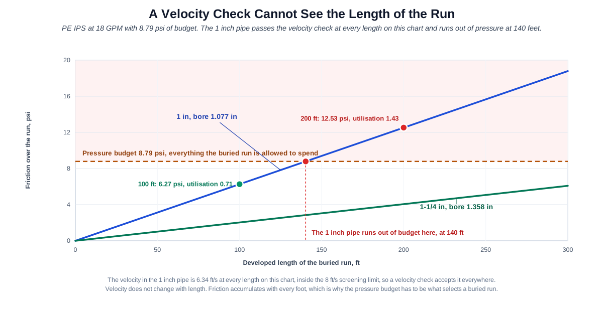
The arithmetic makes it plain. Take a design flow of 18 GPM through PE IPS with 8.79 psi of budget available. Over 100 feet, 1 inch loses 6.27 psi and fits at a utilisation of 0.71. Over 200 feet the same pipe at the same flow loses 12.53 psi, a utilisation of 1.43, and does not fit. Its velocity is 6.34 feet per second at both lengths, comfortably inside the usual 8 feet per second screening limit.
At 200 feet the answer is 1-1/4 inch, losing 4.06 psi at a utilisation of 0.46. At 300 feet the 1 inch pipe would lose 18.80 psi and even the 1-1/4 inch is up to 6.09 psi.
So the practical rule is that long runs need to be sized on pressure and short runs will usually agree with a velocity check. If you are working from a rule of thumb that says a house takes a 1 inch service, that rule was formed on short runs, and the further the main is from the building the less it holds.
Water Service Line Minimum Size
The code sets a floor and the floor is frequently mistaken for an answer.
IPC Section 603.1 requires the water service pipe to be sized to supply water to the structure in the quantities and at the pressures required by the code, and then adds that it shall be not less than 3/4 inch, which is 19.1 mm. IRC Section P2903.8 carries the same figure. The first sentence is the requirement. The 3/4 inch figure exists so that nobody installs a service smaller than that regardless of what the arithmetic says.
The minimum applies to the nominal trade size, not the internal diameter. That distinction matters more than it sounds, because several service materials at 3/4 inch nominal have a bore well under 0.75 inch. A 3/4 inch PE CTS service has an internal diameter near 0.681 inch and still satisfies the code minimum, because the code speaks in trade sizes.
Local jurisdictions raise the floor. New York City requires a minimum water service diameter of 1 inch, which is 25 mm, with no exception for small buildings. Others set their own figures, and the serving water purveyor may add a requirement of its own on top of the plumbing code. Check locally before ordering pipe.
Two things follow. A calculation that returns a size below 3/4 inch is raised to it, and the result should say that the floor governed rather than the hydraulics, because that is a different situation from a size chosen with margin. And a calculation that returns 3/4 inch on its own merits is not automatically compliant either, since the local minimum may be higher.
PE IPS Versus PE CTS and Internal Diameter
Nominal size is a label, not a measurement, and on this page the difference is not academic.
Polyethylene service pipe comes in two dimensional series. IPS follows iron pipe size outside diameters and CTS follows copper tube size outside diameters. Both are sold as 3/4 inch, 1 inch and so on, and both are correct in their own series, but they are not the same pipe. The wall thickness differs too: the IPS service pipe modelled here is SDR 11 and the CTS service pipe is SDR 9, so the CTS wall is proportionally heavier as well as starting from a smaller outside diameter.
The bores differ substantially. A 3/4 inch PE IPS service has an internal diameter near 0.860 inch. A 3/4 inch PE CTS service has an internal diameter near 0.681 inch. That is a difference of about 0.18 inch, and because friction depends on the diameter raised to the power 4.8655, it produces a friction difference of roughly 3.1 times at the same flow.
On a real job that changes the pipe on the order. Take the 200 foot run with 8.79 psi of budget at 18 GPM. In PE IPS the answer is 1-1/4 inch, bore 1.358 inch, losing 4.06 psi at a utilisation of 0.46. In PE CTS the 1-1/4 inch bores 1.069 inch, loses 13.00 psi at a utilisation of 1.48 and does not fit, so the answer is 1-1/2 inch at 5.75 psi and a utilisation of 0.65. Same house, same flow, same length, same budget, and a different pipe on the order.
The same principle applies across materials. Copper Type K, Type L and Type M share an outside diameter and differ in wall thickness, so they differ in bore at the same nominal size. PVC Schedule 40 and Schedule 80 do the same.
This is why the calculator requires the material and the series together and will not compute a size from the nominal figure alone. A tool that accepts PE and 3/4 inch has not been told enough to answer, and one that quietly assumes a series will be wrong for a large share of its users.
Water Service Line Burial Depth
Burial depth is set by two conditions at once and the deeper of them governs.
IPC Section 305.4 requires exterior water supply system piping to be installed not less than 6 inches, which is 152 mm, below the frost line, and not less than 12 inches, which is 305 mm, below grade. IRC Section P2603.5 carries the same rule.
Both apply together, so the answer depends on the local frost line. Where the frost line is 30 inches, the frost condition governs and the pipe goes at least 36 inches deep. Where the frost line is 4 inches, the frost condition would allow 10 inches but the 12 inch floor governs instead. Neither condition alone is the answer.
Without a frost line depth the calculation cannot be completed, and this calculator says so rather than presenting the 12 inch floor as though it were sufficient. Frost depth varies enormously between jurisdictions and it is published by the local building department, so it is worth asking for rather than estimating.
Local amendments raise the requirement, sometimes considerably. Philadelphia requires exterior water supply piping at not less than 36 inches below grade to the top of the pipe regardless of the frost line. A pipe buried above the frost line will freeze in a hard winter, and the remedy is the same excavation that installing it correctly would have avoided.
One practical note that is not about depth. Plastic service piping underground commonly requires a tracer wire or another approved means of locating it later, since a plastic pipe leaves no trace for a metal detector. Conductor size, insulation type and termination are set by the local code edition and the water purveyor rather than by a single universal figure.
Water Service Line and Sewer Separation
The water service and the building sewer frequently run from the same side of the property, and the code is specific about how they may share that ground.
IPC Section 603.2 sets the general rule. Where the water service is installed in the same trench as the building sewer, that sewer must be constructed of materials listed in Table 702.2. Where it is not, the two must be separated horizontally by at least 5 feet, which is 1524 mm, of undisturbed or compacted earth.
Two exceptions cover the cases that actually arise on site.
The first is a crossing. The separation requirement does not apply where the water service crosses the sewer, provided the service pipe is sleeved to at least 5 feet horizontally from the sewer centreline on both sides of the crossing. The sleeve is what makes the crossing acceptable, not the crossing itself.
The second is vertical separation. The requirement also does not apply where the bottom of the water service pipe, within 5 feet of the sewer, is at least 12 inches, which is 305 mm, above the highest point of the sewer. Water above sewer with that clearance is treated as adequate protection.
The reasoning is straightforward. A sewer leak beside a water service under negative pressure is a contamination path, and the separation, the material requirement and the sleeve all exist to break it. Local jurisdictions amend the distances and the authority having jurisdiction is the final word, so confirm before the trench is dug rather than after.
When No Pipe Size Works
Sometimes the honest answer is that the pipe is not the problem.
Run the subtraction chain and the available pressure can come out at zero or below. Take a service with 45 psi at the main, a building 20 feet above it costing 8.66 psi, a 5.25 psi meter, a 12.5 psi loaded filter and 30 psi required at the entry. The chain lands at minus 11.41 psi. The pressure ran out before the pipe was reached, and there is no diameter that changes that, because a larger pipe reduces friction and friction was never the binding constraint.
A calculator that returns its largest modelled size here is producing something that looks like an answer and is not one. This one says the supply cannot serve the building, shows the chain, and names the largest single subtraction, because that is where the conversation has to go next.
The remedies are all outside the pipe. A booster pump adds pressure and is the usual answer when the main is simply too weak for the site. A lower required entry pressure means resizing the interior distribution, which is sometimes available and sometimes not. Reducing a device loss can help, and the loaded filter is often the largest one that can actually be changed, by moving to a larger housing rather than a coarser cartridge. A different point of connection occasionally exists on a stronger part of the main. Elevation is almost never negotiable.
There is a second, milder version of the same result. The available pressure is positive but no size in the modelled ladder fits, usually on a very long run. That is not the same as saying no pipe exists, because service lines are made larger than the residential and light commercial range this page models. It means the job has moved into engineered service design and needs the utility involved.
What is a Water Service Line
The water service line is the buried pipe running from the public water main, or from a private source, to the point where water enters the building. It is one continuous run with no branches, usually between 40 and 300 feet long, and it is the only part of the potable system that is under the ground and outside the building envelope.
That position gives it a set of constraints nothing inside the building has. It must be rated for at least 160 psi at 73.4 F under the plumbing code, a higher pressure rating than interior distribution piping, because it sees main pressure without the benefit of anything upstream reducing it. It must be buried deep enough to stay below the frost line and at least 12 inches below grade. It must keep its distance from the building sewer, or be sleeved where it crosses one. If it is plastic it usually needs a means of locating it later, since nothing about a buried plastic pipe shows on a metal detector.
Hydraulically it is simple. One diameter, one flow, one length, no branches to balance and no most remote fixture to find. What makes it interesting is that it is sized last in the pressure chain and first in the physical order. Everything downstream is decided before this pipe is chosen, so the pipe gets whatever pressure is left, and it is installed before any of those downstream devices exist.
That is also what makes a mistake here expensive. An oversized meter can be swapped, a filter housing can be upsized, a valve can be reset, and interior pipe is behind a wall but reachable. The service line is under the driveway.
Key Facts
- The minimum water service size under IPC Section 603.1 is 3/4 inch, which is 19.1 mm. IRC Section P2903.8 carries the same figure. It is a floor, not a design answer, and it applies to the nominal trade size rather than to the internal diameter.
- Local jurisdictions raise the minimum. New York City requires a minimum water service diameter of 1 inch, which is 25 mm, with no exception for small buildings.
- Water service piping must have a rated working pressure of at least 160 psi at 73.4 F, which is 1103 kPa at 23 C, under IPC Section 605.3. Interior distribution piping is rated at 100 psi at 180 F, which is 689 kPa at 82 C, under Section 605.4. A material acceptable indoors is not automatically acceptable buried.
- 160 psi is a minimum rating rather than a guarantee for any supply condition. Where the main pressure approaches or exceeds it, the product rating and the utility requirements govern.
- Exterior water supply piping must be installed not less than 6 inches, which is 152 mm, below the frost line and not less than 12 inches, which is 305 mm, below grade under IPC Section 305.4. Both conditions apply at once and the deeper governs.
- Local amendments raise burial depth too. Philadelphia requires exterior water supply piping at not less than 36 inches below grade to the top of the pipe regardless of the frost line.
- Where the service shares a trench with the building sewer, IPC Section 603.2 requires that sewer to be built of materials listed in Table 702.2. Otherwise the two need 5 feet, which is 1524 mm, of horizontal separation in undisturbed or compacted earth.
- The separation does not apply where the service crosses the sewer and is sleeved to at least 5 feet horizontally from the sewer centreline on both sides, nor where the bottom of the service within 5 feet of the sewer is at least 12 inches above the highest point of the sewer.
- Permitted service materials under IPC Table 605.3 include copper Types K, L and M, PEX, CPVC, PVC, ductile iron, galvanized steel, PE, PP and stainless steel. Everything in contact with drinking water must conform to NSF 61, and NSF 372 sets the weighted average lead content at 0.25 percent.
- The internal diameter drives friction, and it depends on the dimensional series as well as the material. A 3/4 inch PE IPS service has an internal diameter near 0.860 inch and a 3/4 inch PE CTS service near 0.681 inch. At 18 GPM the friction differs by a factor of about 3.1.
- Every foot of rise from the main to the building entry costs 0.433 psi, which is 2.99 kPa. A fall returns it at the same rate.
- Hazen-Williams is the standard friction method for water service conditions. It is an approximation for ordinary water temperatures in turbulent flow, not a universal fluid equation.
- A useful check on any implementation: 18 GPM through an internal diameter of 0.860 inch at a coefficient of 150 loses 43.25 feet per 100 feet, which is 18.73 psi per 100 feet.
- Velocity limits of 8 feet per second for cold water, and 4 feet per second where the water is aggressive, are field practice rather than a code requirement on the service line specifically.
- Plastic service piping underground commonly requires a tracer wire or another approved locating means. Conductor size, insulation and termination are set locally rather than by one universal figure.
Applications
- A designer finishing a pressure budget has sized the meter, the backflow assembly and the filter and needs to know whether anything is left for the pipe that carries water to the building.
- A contractor quoting a new service on a long rural lot checks whether the run length pushes the size up before the trench is dug, since the cost difference between sizes is small and the cost of redoing it is not.
- An engineer working a site with a fall from the main to the building finds out how much pressure the slope returns, which sometimes turns a marginal service into a comfortable one.
- A homeowner with weak pressure and a long buried service checks whether the existing line is the constraint or whether the pressure was already spent before it.
- A plans reviewer checks that the service size on a submittal was derived from an available pressure rather than from a velocity check, and that the code minimum and local minimum were both applied.
- A contractor choosing between two materials at the same nominal size sees that the dimensional series changes the answer, and orders the right one rather than the one the catalogue listed first.
Example Calculations
Example 1. Where the pressure went
Given: 60 psi at the main, which is 413.7 kPa. The building sits 8 feet above the main. The meter loses 5.25 psi, a loaded filter loses 12.5 psi, and the interior calculation needs 30 psi at the building entry.
Elevation costs 8 times 0.433, which is 3.46 psi. The chain runs 60 minus 3.46 minus 5.25 minus 12.5 minus 30, and what is left for the service line is 8.79 psi, or 60.6 kPa.
Result: the pipe gets 8.79 psi out of 60. The meter, the filter, the slope and the building itself claimed the rest, and the largest single claim was the building at 30 psi. That is the number worth showing, because it tells you which term to attack if the answer comes back uncomfortable.
Example 2. The same pipe, twice the length, a different answer
Given: the budget from Example 1, a design flow of 18 GPM, which is 68.14 L/min, and PE IPS service pipe.
Over a 100 foot run, 1 inch loses 6.27 psi against the 8.79 available, a utilisation of 0.71. It fits.
Over a 200 foot run the same pipe at the same flow loses 12.53 psi, a utilisation of 1.43. It does not fit. Its velocity has not changed: 6.34 feet per second at both lengths, comfortably inside the 8 feet per second limit.
Result: a velocity check accepts 1 inch at both lengths. The pressure budget accepts it at one. At 200 feet the answer is 1-1/4 inch, losing 4.06 psi at a utilisation of 0.46 and running at 3.99 feet per second. The service line went up a size for pressure, not for velocity, and nothing about the flow changed.
Example 3. The series changes the pipe on the order
Given: the 200 foot run from Example 2, but the material is PE CTS rather than PE IPS.
The nominal sizes are the same and the internal diameters are not. PE CTS at 1-1/4 inch bores 1.069 inch against 1.358 inch for IPS, and it loses 13.00 psi over the run, a utilisation of 1.48. It does not fit. The next size up, 1-1/2 inch, loses 5.75 psi at a utilisation of 0.65 and does.
Result: same house, same flow, same length, same budget, and a different pipe. IPS selects 1-1/4 inch and CTS selects 1-1/2 inch. This is why the calculator asks for the series and will not compute a size without it. A tool that accepts material PE and nominal 3/4 has not been told enough to answer.
Example 4. A fall in the ground returns pressure
Given: the Example 1 devices, but the building sits 10 feet below the main rather than 8 feet above it.
Elevation is now a gain of 10 times 0.433, which is 4.33 psi. The chain runs 60 plus 4.33 minus 5.25 minus 12.5 minus 30, leaving 16.58 psi for the service line, which is 114.3 kPa.
Result: nearly twice the budget of Example 1 from the ground alone. The elevation is entered as a positive 10 feet with the building below the main, not as a negative number, and the result labels the term a gain rather than a loss.
Example 5. When no pipe helps
Given: 45 psi at the main, the building 20 feet above it, the same meter and filter losses, and 30 psi required at the entry.
Elevation costs 8.66 psi. The chain runs 45 minus 8.66 minus 5.25 minus 12.5 minus 30, which is minus 11.41 psi. There is nothing left, and the shortfall exists before the pipe is considered.
Result: no diameter solves this. The calculator says so, shows the chain, names the largest subtraction, and points at a booster pump. Returning the largest pipe in the list would look like an answer and would not be one.
Example 6. The code minimum overrides the arithmetic
Given: a short run at a low flow where the friction calculation would allow 1/2 inch comfortably.
The code minimum service size is 3/4 inch nominal under IPC 603.1, so the size is raised. If the local jurisdiction requires 1 inch, as New York City does, it is raised again.
Result: 3/4 inch, or 1 inch locally, and the result says the floor governed rather than the hydraulics. The comparison is on the nominal trade size, not the internal diameter, which matters because several materials at 3/4 inch nominal have a bore well under 0.75 inch.
Example 7. A static reading is not a flowing one
Given: the Example 1 site, but the only pressure figure available is a 60 psi static reading taken at a hose bibb with nothing running. No flowing or residual figure has been obtained from the utility.
The calculation still runs, and it returns the same 8.79 psi of available pressure and the same recommended size, because the arithmetic does not know the difference. What changes is the confidence attached to it: the result is flagged as based on a static figure and described as optimistic.
Result: usable for a first pass, not for a final size. The real flowing pressure at peak demand is lower by an amount that cannot be estimated from the static reading, so the true budget is smaller than 8.79 psi and the true answer may be one size larger. Ask the utility for the residual pressure at the design flow before the trench is dug.
Example 8. Clean filter or loaded filter changes the pipe
Given: the Example 2 site with the 200 foot run, and a cartridge filter on the service. Its clean pressure drop is 2.5 psi and its loaded drop at change-out is 12.5 psi.
Budget it clean and the available pressure is 18.79 psi. At that budget the 1 inch PE IPS at 12.53 psi fits, a utilisation of 0.67, and 1 inch is the answer.
Budget it loaded and the available pressure is 8.79 psi. Now the 1 inch does not fit at all and the answer is 1-1/4 inch.
Result: one input decides the pipe. The clean figure is the smallest drop the filter will ever produce and it describes one day in the cartridge's life, while the loaded figure describes the day before it is changed. Use the loaded number here, because the service line has to work on that day too and it is the one component that cannot be upsized afterwards.
Standards & References
- 2024 International Plumbing Code, Chapter 6, Water Supply and Distribution Contains Section 603.1 for the minimum water service size, Section 603.2 for separation from the building sewer, and Section 605.3 with Table 605.3 for approved service materials and the 160 psi rating requirement.
- 2024 International Plumbing Code, Section 605, Materials, Joints and Connections The section that carries the service material table and the pressure rating requirements, including the difference between the 160 psi at 73.4 F service rating and the 100 psi at 180 F interior distribution rating.
- 2024 International Plumbing Code, Chapter 3, General Regulations Contains Section 305.4 with the burial depth requirement of not less than 6 inches below the frost line and not less than 12 inches below grade. Both conditions apply at once and the deeper governs.
- UpCodes, Section 603.1, Size of Water Service Pipe The text of the section across several code editions and jurisdictions, free to read. Useful for checking whether a local amendment has raised the 3/4 inch minimum where the work is being done.
- NSF/ANSI/CAN 61, Drinking Water System Components Every material in contact with drinking water must conform to this standard, and NSF 372 sets the weighted average lead content at 0.25 percent. The searchable listing confirms what a specific product is certified to.
Units
Pressure is entered and reported in pounds per square inch and kilopascals, with the equivalent in feet of head where useful. Convert with 1 psi equal to 6.895 kPa and 1 psi equal to 2.31 feet of head. The 160 psi service rating is 1103 kPa.
Flow is entered in gallons per minute or litres per minute. Convert with 1 GPM equal to 3.785411784 L/min, so 18 GPM is 68.14 L/min.
Length is entered in feet or metres, with 1 foot equal to 0.3048 m, so a 200 foot service run is 60.96 m. Burial depth and the frost line are reported in inches or millimetres, with 1 inch equal to 25.4 mm, so the 12 inch floor is 305 mm and a 36 inch depth is 914 mm. The friction gradient is stated in psi per 100 feet in Imperial and kPa per 100 m in Metric.
Nominal pipe sizes stay in inches in both unit systems, because that is how service pipe is specified, ordered and inspected wherever these codes apply. A 1-1/4 inch service is a 1-1/4 inch service whichever units the rest of the calculation is in.
Internal diameters are reported in inches to three decimals, because friction depends on the diameter raised to the power 4.8655 and a rounded bore produces a visibly different answer. Metric adds the millimetre equivalent beside the inch figure rather than replacing it.
The internal unit selector governs the fields, labels, math, on-screen result and any exported result, and it takes priority over any site-wide unit switch. Switching converts the values you entered rather than reinterpreting them, so 60 psi becomes 413.7 kPa and returns to exactly 60 psi when switched back.
Limitations
- This calculator sizes one buried run from the main to the building entry. It does not size the interior distribution network, which is a branching system with a most hydraulically remote fixture and belongs to the water pipe sizing calculation.
- It does not derive the device losses it subtracts. The meter loss, the backflow assembly loss and the filter loss each come from their own calculation, and this page takes them as inputs.
- It does not model a pressure reducing valve as a loss. A valve sets the pressure downstream of itself rather than consuming pressure in proportion to flow, and a valve at the building entry sits downstream of the service line entirely. The required entry pressure already expresses what the building needs.
- Only devices between the main and the building entry belong in the chain. A meter, backflow assembly or filter located inside the building belongs to the interior calculation, and entering it here as well will understate the available pressure.
- The material and dimensional series are required for size selection, and the calculation will not proceed to a diameter without them. The internal diameter depends on both, and there is no safe default.
- The internal diameter table covers PE in IPS SDR 11 and CTS SDR 9, PEX in CTS SDR 9, PVC in Schedule 40 and Schedule 80, copper in Types K and L, and CPVC in CTS SDR 11. Ductile iron, galvanized steel, PP, stainless steel and copper Type M are permitted service materials under IPC Table 605.3 and are not modelled here.
- Hazen-Williams is an approximation for water at ordinary service temperatures in turbulent flow. It does not replace a manufacturer flow table or a utility requirement, and it does not apply to other fluids. Aged galvanized steel has a roughness coefficient that falls with service life and is not modelled.
- The velocity limits shown are field practice rather than a code requirement on the service line. They are a sanity check on the selected size and they do not select it.
- The modelled size ladder runs from 3/4 inch to 2 inch nominal, which covers residential and light commercial service. A larger service is an engineered design and this page will say so rather than extrapolate.
- Burial depth, sewer separation and locating requirements are reported from the model code. Local jurisdictions amend all three, and the serving water purveyor may add requirements of its own that override what is shown here.
Common Mistakes to Avoid
- Sizing the service line on velocity alone. A velocity check does not know how long the run is, so it will accept a pipe that spends more pressure over 200 feet than the budget contains. The pressure budget governs and the gap between the two grows with every foot.
- Using interior pipe sizing as the service line answer. The interior network and the buried service answer different questions. The service line is sized from the pressure remaining at the building entry, not from the branch and riser layout inside the building, and the two frequently come out at different sizes.
- Using static main pressure. The static reading is taken with nothing flowing and it is the highest pressure the main will ever show. Size on the flowing figure at peak demand, or on the utility residual pressure, or the answer is optimistic in the direction that matters.
- Entering a material without its dimensional series. PE IPS and PE CTS at the same nominal size have different bores, and on a long run they select different pipe. Naming the material is not enough to size the line.
- Using the nominal size as the internal diameter. Friction depends on the bore raised to the power 4.8655, so a 3/4 inch pipe with a 0.681 inch bore behaves nothing like one with a 0.860 inch bore.
- Budgeting the clean filter loss. A cartridge is only clean on the day it is fitted, and the loaded figure is several times larger. Using the clean number here produces a service line that works for a few weeks.
- Subtracting a device twice. A meter or filter inside the building belongs to the interior calculation, and the required entry pressure already accounts for what happens downstream of the entry point. Only devices on the buried run belong in this chain.
- Treating a pressure reducing valve as a loss. It sets downstream pressure rather than consuming it, and the required entry pressure already expresses the downstream requirement. Adding a valve loss on top counts the same pressure twice.
- Forgetting irrigation in the design flow. A service line frequently carries a hose bibb or an irrigation zone that can run alongside domestic demand, and if it can run at the same time it belongs in the peak flow.
- Burying to the frost line and stopping there. The requirement is the greater of two conditions, so a shallow frost line still needs 12 inches of cover, and local amendments raise both figures.
- Assuming the code minimum is a design answer. Three quarters of an inch is a floor. The first sentence of the section requires the pipe to be sized to supply the structure at the required pressures, and that is the actual requirement.
Frequently Asked Questions
What size water service line do I need?
What is the minimum water service line size?
How deep does a water service line need to be buried?
Why does my service line need to go up a size when nothing about the flow changed?
Does the pipe material change the size I need?
Can I use the static pressure reading from the utility?
What if the calculation says no pipe size works?
Does the service line need to be the same size as the interior piping?
What pressure should I have at the building entry?
Should I include the meter and the backflow preventer in this calculation?
Does a loaded filter really matter for sizing a service line?
What if my service line is longer than 300 feet?
Can a fall from the main to the building help?
Frequently Used Together
Engineers often use these calculators in combination for complete project workflows:
Related Calculators
Explore similar calculators that might be useful for your project:
Plumbing Quick Reference — Keep It On Your Phone On Site
A 10-page field reference for catching pressure, velocity, slope, and pump-sizing mistakes before you order pipe, close a wall, or add a booster.
- Velocity limits, fixture pressure minimums, drain slope, and the 80 psi ceiling in one table
- Worked examples that show why a single pressure number gives four different answers
- Keep it on your phone, or print the two field-check pages
Free PDF. Calculators stay free. Unsubscribe anytime.
Calculate
This selector governs every field, label, result and export on this page, and it takes priority over the site header switch. Switching converts the values you entered rather than reinterpreting them, so 60 psi becomes 413.7 kPa and returns to exactly 60 psi when you switch back. Nominal pipe sizes stay in inches in both systems, because that is how service pipe is specified, ordered and inspected wherever these codes apply.
Supply and Demand
The only credit in this calculation; everything else is a debit. Use the flowing pressure at peak demand, or better, the residual pressure the utility records at a stated flow from hydrant flow testing. A static reading taken at a hose bibb with nothing running is the highest figure the main will ever show and it is not the figure this calculation needs.
The basis changes the confidence in the answer rather than the arithmetic. Static pressure is measured with nothing flowing and is higher than what you will have at peak demand, sometimes considerably, and the difference cannot be estimated from the static reading. The calculator flags a static or unknown basis rather than quietly treating it as flowing.
The peak simultaneous demand the buried run has to carry. It normally comes from a fixture unit conversion. Anything able to run alongside domestic demand belongs in this figure, which on a service line usually means a hose bibb or an irrigation zone.
Where the flow figure came from. A fixture unit conversion is the usual source on a dwelling; a direct entry is normal where the demand is specified. An unknown basis is flagged rather than assumed, because the design flow is one of only two terms in the friction calculation.
A service line frequently carries irrigation or a hose bibb that can run at the same time as domestic demand, and forgetting it is one of the more common ways a design flow comes out low. If it can run at the same time, it belongs in the peak flow rather than beside it.
Measured from the tap at the main to the point where the pipe enters the building, following the route the trench will take rather than the straight line on the plan. Length is the variable people underestimate: velocity does not change with it at all, and friction accumulates with every foot.
Taken from the interior calculation rather than invented here. It is the pressure the distribution system needs at the point of entry, before interior distribution begins, so the most hydraulically remote fixture still receives its required flowing pressure after interior elevation and interior friction. It is usually the largest single term in the chain.
Service Material
Required for size selection, and the pressure budget is returned without it. There is no safe default: the internal diameter depends on the material and there is no generic plastic to fall back on. IPC Table 605.3 permits more service materials than this page models, and a material that is not tabulated returns a state rather than a guess.
Required alongside the material, because naming the material is not enough to size a service line. A 3/4 inch PE IPS service bores 0.860 inch and a 3/4 inch PE CTS service bores 0.681 inch, and since friction depends on the bore raised to the power 4.8655 the two differ by a factor near 3.1 at the same flow. On a long run they select different pipe. The series shown in brackets is the material each one belongs to.
Elevation and Device Losses (all optional)
Always a positive distance. The direction is the separate choice below, so there is no negative number to enter and no sign to get wrong. Every foot of rise costs 0.433 psi and every foot of fall returns the same, which on a sloping site is frequently larger than the friction in the pipe.
A rise costs pressure and a fall returns it, at the same 0.433 psi per foot. The result labels the elevation row a loss or a gain according to this choice rather than according to the sign of the number you typed.
The pressure the meter takes at the design flow, from the water meter sizing calculation. Only enter it where the meter sits between the main and the building entry point you are working to. A meter inside the building belongs to the interior calculation and subtracting it in both places counts the same pressure twice.
The pressure the backflow prevention assembly takes at the design flow, from the backflow preventer calculation. A reduced pressure assembly takes considerably more than a double check, and both impose a minimum loss before any water moves at all. Same location rule as the meter.
The pressure a cartridge filter takes when it is loaded and due for changing, not when it is clean. The clean figure is the smallest drop the cartridge will ever produce and it describes one day in its life. This budget needs the figure from the day before the cartridge is changed, because the service line has to work on that day too.
A generic line for anything else that consumes pressure between the main and the building entry. There is deliberately no pressure reducing valve field: a valve sets the pressure downstream of itself rather than consuming pressure in proportion to flow, and a valve at the building entry sits downstream of the service line entirely. Where a valve genuinely sits on the buried run, enter its measured loss here.
Fittings and the corporation stop add friction, and both forms of allowance are in common use. The equivalent length form adds a stated distance to the run; the percentage form adds a proportion of it. Either way the allowance is added to the developed length before friction is calculated.
Added to the developed length of the run. A buried service has few fittings compared with an interior network, but the tap, the corporation stop, the curb stop and the entry bend are all real and they all cost pressure.
Installation Checks (all optional)
Published by the local building department and worth asking for rather than estimating, because it varies enormously between jurisdictions. Without it the burial depth cannot be evaluated: IPC Section 305.4 sets the greater of two conditions and only one of them can be read without a frost depth. Left blank, the calculator says the depth was not evaluated rather than presenting the 12 inch floor as though it were sufficient.
IPC Section 603.2 governs how the water service and the building sewer may share ground, and the requirement depends entirely on the relationship between them. Left unknown, the calculator reports the separation as not evaluated and never implies a pass, because a sewer leak beside a water service under negative pressure is a contamination path.
Local jurisdictions raise the code floor and the serving water purveyor may add a requirement of its own. New York City requires a minimum water service diameter of 1 inch with no exception for small buildings. Where a local minimum is larger than the size the hydraulics chose, the calculator raises the size and names the local requirement as what governed.