Water Meter Sizing Calculator — Safe Maximum Flow, Continuous Duty, and Pressure Loss
On this page
Calculate
This selector governs every field, label, result and export on this page, and it takes priority over the site header switch. Switching converts the values you entered rather than reinterpreting them.
The maximum concurrent flow through the meter. If irrigation or a process load can run at the same time as domestic demand, include it here. A water supply fixture unit calculation is the usual source for this number.
Sustained Load (Optional)
Irrigation, tank filling, cooling makeup or a process draw. This is a duration check on part of the peak, not an extra load added to it, so do not enter irrigation twice.
The allowance on the safe maximum is 2 hours in a 24-hour period for displacement meters. Left blank, a sustained flow above the continuous rating is measured against that continuous rating rather than passing silently.
Checks (Optional)
A single fixture or a small continuous draw. Leaving it blank returns an advisory rather than a silent pass on registration.
Check a specific meter instead of receiving a recommendation. The recommendation is still shown alongside for comparison.
The share of the pressure budget allocated to the meter. The test uses the governing loss, which is the larger of the loss at peak flow and the loss at sustained flow.
Manufacturer Loss Curve (Optional)
A published loss for the actual meter. Enter it together with the flow it was stated at. Published curves for the same nominal size differ by roughly a factor of two, so this is worth entering whenever the budget is tight.
Both override fields are required together. The calculator scales from your point with the same square law instead of using its own curve.
Overview
A water meter is not selected by the size of the pipe it sits in. It has to pass the peak flow, survive sustained duty inside its continuous rating, keep pressure loss within the budget available at the building, and still register low flows accurately enough to show normal use and leaks. This calculator runs all four checks against the AWWA displacement meter ratings and returns a size, a verdict, and the pressure the meter will cost you.
Two facts drive most of the wrong answers in the field. The first is that the safe maximum operating capacity printed against each meter size is not a rating for continuous use. It carries a duration limit, so a load that clears the safe maximum on paper can still be outside the standard once it runs for hours. The second is that a meter can be wrong in both directions. Too small produces heavy pressure loss and operation past the rating. Too large measures low flow with no assured accuracy, which loses both billed water and the ability to see a leak in the consumption record. The safest-looking larger meter is often the one that loses low-flow accuracy.
This calculator sizes the meter only. It does not size pipe, select a pump, or compute system pressure. It produces the meter loss figure that a pressure budget needs, and it hands off to the water pressure and pipe sizing tools from there.
What to Look at First
Recommended size and the governing utilization. The headline result is the meter size plus the governing utilization, and the output names which check produced it. Utilization at or below 0.85 is a pass, above 0.85 to 1.00 is marginal, and above 1.00 is past the governing AWWA rating. When a sustained load is present the governing rating is often the continuous maximum, which is half the safe maximum, so the duty check can govern even when the peak check looks comfortable.
The duty state, not just the number. A sustained flow between the continuous maximum and the safe maximum is legitimate while it stays brief and becomes a violation once it runs for hours. The result reports one of three outcomes: inside the continuous rating, limited duration use within the 2-hour allowance, or measured against the continuous rating because the allowance was exceeded or the hours were left blank.
Meter loss in the pressure budget. The governing loss is the larger of the loss at peak flow and the loss at sustained flow, reported in psi and kPa with the equivalent feet of head. This is the meter line for a pressure budget, and at a small meter carrying a large flow it can exceed 12 psi, more than many designers allocate to the entire service.
The sizing and registration line. Capacity and sizing are separate verdicts on separate lines. An oversize caution or an under-registration risk can sit beside a green capacity pass, and that combination is the more common error in practice: the meter passes every flow check and still measures ordinary use with no assured accuracy.
How to Use This Calculator
Choose the unit system with the calculator's own selector. Every field, label, result and export follows that selector, and switching it converts the values you already entered.
Enter the peak design flow. This is the maximum concurrent flow through the meter. If irrigation or a process load can run at the same time as domestic demand, include it here. A fixture unit calculation is the usual source for this number.
If part of that flow runs for a long stretch, enter it as the sustained flow together with the hours per day it runs. Irrigation, tank filling, cooling makeup and process loads belong here. This is a duration check on part of the peak, not a second load added on top, so do not enter irrigation twice.
Enter the expected typical low flow if you know it. A single fixture or a small continuous draw is the case that matters. Leaving it blank returns an advisory rather than a silent pass.
Enter a candidate meter size if you want to check a specific meter instead of receiving a recommendation.
If you have a pressure budget for the meter, enter the allowable loss in psi or kPa, and the calculator will test the selected meter against it.
If you have the manufacturer loss curve, enter a known loss and the flow it was stated at. The calculator will scale from your point instead of the representative curve, which matters because published curves differ widely.
Read the recommended size, the governing utilization and which check produced it, the pressure loss at peak and at sustained flow, and any flags for duration, registration, oversizing or budget.
The safe maximum operating capacity is not a rating for continuous use. It carries a duration limit of roughly 10 percent of usage or 2 hours in a 24-hour period for displacement meters, which is why the hours per day field changes the answer rather than decorating it.
Inputs & Outputs
Inputs
Outputs
Water Meter Sizing Formula
The sizing comes down to four checks. The size you want is the one that clears all of them.
- Peak check, the peak flow against the safe maximum for that size:
U_peak = peak_gpm / safe_max - Duty check, the sustained flow against the continuous rating, or against
safe_maxwhen the load is brief:U_duty = duty_gpm / continuous - Governing utilization, the worse of the two, rounded to 2 decimals before banding:
U = max(U_peak, U_duty) - Loss, the square law on the k for that meter size:
loss = k * flow ^ 2
The calculator uses a fixed model. Values are stored at full precision and rounded only for display, so converting between unit systems and back returns the original numbers.
INPUTS
peak_gpm: peak design flow, the maximum concurrent flow through the meter. Required.duty_gpm: sustained flow, irrigation or process. Optional.duty_hours: hours per day at the sustained flow. Optional.low_gpm: expected typical low flow. Optional.size: candidate meter size. Optional.budget_psi: allowable meter loss in the pressure budget. Optional.override_loss_psiandoverride_flow_gpm: a manufacturer loss and the flow it was stated at. Optional, entered together.
LADDER, AWWA C700 displacement meters
  size      safe_max   continuous   low_reg        k
  5/8          20          10        0.25      0.0373
  3/4          30          15        0.50      0.0162
  1            50          25        0.75      0.0055
  1-1/2       100          50        1.50      0.00187
  2           160          80        2.00      0.00068
  continuous is 50 percent of safe_max at every size
  allowed_hours = 2 per day for displacement meters

INPUT GUARDS
  IF peak_gpm is blank                         THEN INCOMPLETE
  IF peak_gpm <= 0, or any value is negative   THEN OUT_OF_RANGE
  IF duty_hours entered without duty_gpm       THEN INCOMPLETE
  IF override entered with flow <= 0,
     or only one of the two override fields    THEN OUT_OF_RANGE
  IF duty_gpm > peak_gpm                       THEN warn, peak is understated
  IF peak or duty above the largest size       THEN refer to turbine or compound

PEAK CHECK
  U_peak = peak_gpm / safe_max

DUTY CHECK, a duration test on part of the peak, not an extra load
  IF duty_gpm blank or 0
     U_duty = none                          duty_state = NOT_EVALUATED
  ELSE IF duty_gpm <= continuous
     U_duty = duty_gpm / continuous         duty_state = CONTINUOUS_OK
  ELSE IF duty_gpm <= safe_max AND duty_hours <= allowed_hours
     U_duty = duty_gpm / safe_max           duty_state = LIMITED_DURATION_USE
  ELSE IF duty_gpm <= safe_max AND duty_hours blank
     U_duty = duty_gpm / continuous         duty_state = DURATION_UNKNOWN
  ELSE IF duty_gpm <= safe_max
     U_duty = duty_gpm / continuous         duty_state = DURATION_LIMIT_EXCEEDED
  ELSE
     U_duty = duty_gpm / continuous         duty_state = EXCEEDS_SAFE_MAX

GOVERNING UTILIZATION
  U = max(U_peak, U_duty when numeric), rounded to 2 decimals BEFORE banding
  the output names which check governs

RECOMMENDATION, targets the PASS band rather than the bare AWWA rating
  the smallest size where rounded U <= 0.85
     and duty_state is NOT_EVALUATED, CONTINUOUS_OK or LIMITED_DURATION_USE
  the smallest size merely within the rating is also reported when it differs

PRESSURE LOSS, square law
  IF an override is entered
     k = override_loss_psi / override_flow_gpm ^ 2   MANUFACTURER_OVERRIDE_ACTIVE
  ELSE
     k = the representative k for that size          REPRESENTATIVE_CURVE_NOTE

  loss_peak      = k * peak_gpm ^ 2
  loss_duty      = k * duty_gpm ^ 2       (0 when duty is not entered)
  loss_governing = max(loss_peak, loss_duty)

VERDICT BANDS, applied to U after rounding
  U <= 0.85          PASS, within rating with headroom
  0.85 < U <= 1.00   MARGINAL, within rating with no headroom
  U > 1.00           FAIL, past the governing AWWA rating

INDEPENDENT FLAGS, none of which change the band
  duty above continuous, within safe max, inside allowance  LIMITED DURATION USE
  duty above continuous, hours blank                        DURATION UNKNOWN
  duty above continuous, hours over the allowance           DURATION LIMIT EXCEEDED
  low_gpm < low_reg                                         UNDER REGISTRATION RISK
  a smaller size satisfies both flow checks                 OVERSIZED
  loss_governing > budget_psi                               LOSS OVER BUDGET

UNIT CONVERSIONS
  L/min = GPM * 3.785411784
  kPa   = psi * 6.895
  feet of head = psi * 2.31, taken from the psi figure as displayed, so the
                 same loss reads the same feet of head in both unit systems
  every entry is held internally in GPM and psi at full precision and is
  converted only when it is drawn into a field, so the math never works from
  a rounded figure and a unit switch never changes what you entered
Water Meter Size Chart
This is the domestic displacement meter ladder the calculator works from. Each size carries three numbers that matter, and they are not interchangeable: the safe maximum is a short-burst ceiling, the continuous maximum is what the meter can hold indefinitely, and the low-flow figure is where the specified accuracy band begins.
5/8 in, often listed as 5/8 x 3/4: safe maximum 20 GPM or 75.7 L/min, continuous maximum 10 GPM or 37.9 L/min, low-flow registration 0.25 GPM or 0.95 L/min.
3/4 in: safe maximum 30 GPM or 113.6 L/min, continuous maximum 15 GPM or 56.8 L/min, low-flow registration 0.5 GPM or 1.89 L/min.
1 in: safe maximum 50 GPM or 189.3 L/min, continuous maximum 25 GPM or 94.6 L/min, low-flow registration 0.75 GPM or 2.84 L/min.
1-1/2 in: safe maximum 100 GPM or 378.5 L/min, continuous maximum 50 GPM or 189.3 L/min, low-flow registration 1.5 GPM or 5.68 L/min.
2 in: safe maximum 160 GPM or 605.7 L/min, continuous maximum 80 GPM or 302.8 L/min, low-flow registration 2.0 GPM or 7.57 L/min.
Two patterns are worth carrying in your head. The continuous maximum is exactly half the safe maximum at every size on this ladder, so once you know one you know the other. And the pressure loss at the continuous rating stays in a narrow band across the whole ladder, from about 3.4 psi at 1 in to about 4.7 psi at 1-1/2 in, which means the sizes are scaled so that continuous duty costs roughly the same pressure whichever one you land on.
The AWWA displacement standard covers meters from 1/2 in upward. This calculator starts the ladder at 5/8 in because that is the smallest size in common domestic service, and it stops at 2 in because above that the practical choice moves to turbine and compound meters.
Safe Maximum vs Continuous Duty
The safe maximum operating capacity is the number most people read off the table, and it is the one most often misread. It is not a rating for running the meter all day. It carries a duration limit: operation at that rate should stay within roughly 10 percent of usage, or about 2 hours in a 24-hour period, for a displacement meter. Turbine meters carry a more permissive allowance.
The continuous maximum is the rate the meter can hold indefinitely, and on this ladder it is exactly half the safe maximum. Between those two numbers sits a band that is neither clearly allowed nor clearly forbidden, and that band is where sizing decisions actually go wrong. A flow in that band is legitimate as a burst and becomes a violation once it runs for hours.
This is why duration is an input on this page rather than a footnote. Take a 5/8 in meter with a 12 GPM load. Against the 10 GPM continuous rating that flow is too high, but against the 20 GPM safe maximum it is comfortable. Run it for 1 hour a day and it is a limited-duration load measured against the safe maximum, giving 0.60. Run the same 12 GPM for 3 hours and it has become continuous duty, measured against the continuous rating, giving 1.20 and a failure. Identical flow, identical meter, opposite answers.
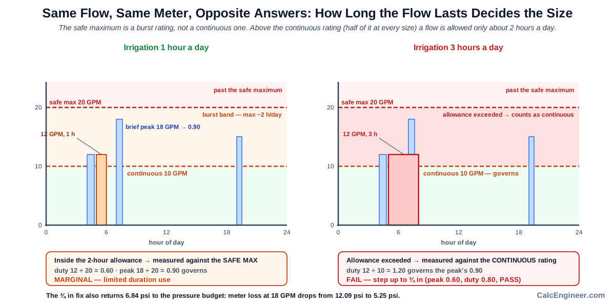
The loads that fall into this trap are always the long ones: irrigation zones, tank and pool filling, cooling tower makeup, and process draws. Domestic fixture demand is bursty by nature and rarely triggers it. If a page asks only for peak GPM and never asks how long the flow lasts, it cannot tell these cases apart.
Water Meter Pressure Loss
Every mechanical meter takes pressure to drive it, and the amount is not small at the lower end of the ladder. Loss rises with the square of flow, so it climbs far faster than most people expect. On a 5/8 in meter, 5 GPM costs about 0.93 psi, 10 GPM costs about 3.73 psi, 20 GPM costs about 14.92 psi, and 30 GPM would cost about 33.6 psi. Doubling the flow roughly quadruples the loss.
Stepping up one size collapses that number. At 20 GPM the representative loss is about 14.92 psi at 5/8 in, 6.48 psi at 3/4 in, and 2.20 psi at 1 in, which is 103, 45 and 15 kPa. That is 8.44 psi recovered from a single size step and 12.72 psi from two, which is more pressure than many designers allocate to the entire service.
This is the number the calculator exists to produce for the rest of the design. A pressure budget starts from the pressure available at the main and subtracts the meter, elevation, devices and pipe friction on the way to the worst fixture. The meter line is often the largest single item after elevation, and it is the one most often left out because there is nowhere obvious to look it up.
One caution about the figures above. They come from a representative curve, not from a standard. The AWWA standards define capacity ratings and accuracy, but the pressure loss of any specific meter is product data, and published curves for the same nominal size differ by roughly a factor of two. A modern low-loss 5/8 in model may list about 7 psi at 20 GPM where a generic curve gives about 15 psi. When you have the manufacturer curve, enter a known loss together with the flow it was measured at and the calculator will scale from your point using the same square law instead of its own curve. That is worth doing whenever the budget is tight, because the difference is large enough to change which size you buy.
Low-Flow Registration and Oversizing
Sizing has an upper bound as well as a lower one, and the upper bound is invisible to a capacity check. Every displacement meter has a flow below which its accuracy is no longer specified: 0.25 GPM on a 5/8 in meter, rising through 0.5, 0.75 and 1.5 to 2.0 GPM on a 2 in. Above that figure the meter reads within its accuracy band. Below it, the measuring element is barely being driven and what gets recorded is no longer assured.
That matters because most water use is small. A single fixture, a slow fill, a running toilet or a dripping joint all sit at the bottom of the range. Put a 2 in meter on a building whose typical draw is half a gallon a minute and ordinary consumption falls below the point where the meter is specified to be accurate. The water is delivered and imperfectly recorded, and a leak that would show up as a rising baseline never appears in the data at all.
Oversizing is the more common error, not the rarer one, and it has a clear cause. Fixture unit methods were calibrated when fixtures used far more water than they do now, so peak estimates come out high, and a margin often gets added on top of an already conservative number. Research that logged flow at 10-second intervals for two weeks across 43 buildings with water-conserving fixtures concluded that 37 of them would likely have been better served by a smaller meter.
The practical rule is that a comfortable capacity utilization is not by itself a good result. If a smaller size still passes the peak and duty checks, the larger one is buying pressure headroom at the cost of low-end accuracy, and that trade should be made deliberately. The calculator raises an oversize flag on its own line rather than burying it under a green verdict, and it compares one size down and one size up so the trade is visible. One qualifier: the low-flow figure marks where specified accuracy begins, not a hard cutoff where the register stops turning.
What Is Water Meter Sizing
A displacement water meter measures volume mechanically. Water entering the chamber moves an oscillating piston or a nutating disc, each cycle carries a fixed quantity through, and a register counts the cycles. Because the measuring element is physically driven by the water, the meter has both a floor and a ceiling. Below a certain flow the element barely moves and accuracy is no longer assured. Above a certain flow the element is being driven harder than it was designed for, wear accelerates, and the pressure needed to push water through climbs steeply.
The AWWA standard for these meters puts numbers on both ends. Each size carries a safe maximum operating capacity, a maximum rate for continuous duty that is half of it, and a low-flow figure marking where the specified accuracy band begins. Sizing means fitting your demand pattern between those limits, not matching the meter to the pipe.
Sizing is therefore a four-check problem rather than a lookup. The flow has to fit under the ceiling, the part of it that runs for hours has to fit under the continuous rating, the pressure it costs has to fit the budget, and the small flows the building actually spends most of its time at have to sit above the accuracy floor. A meter can pass any three of those and still be the wrong choice.
Key Facts
- The governing standard for these meters is AWWA C700, cold-water meters of the displacement type. The current edition is C700-2024.
- This calculator models the common domestic ladder from 5/8 in through 2 in. The standard itself starts at 1/2 in, a size rarely used for domestic service.
- Safe maximum operating capacity by size: 20 GPM at 5/8 in, 30 at 3/4 in, 50 at 1 in, 100 at 1-1/2 in, 160 at 2 in. In metric that is 75.7, 113.6, 189.3, 378.5 and 605.7 L/min.
- Maximum rate for continuous duty is exactly 50 percent of the safe maximum at every one of those sizes: 10, 15, 25, 50 and 80 GPM, or 37.9, 56.8, 94.6, 189.3 and 302.8 L/min.
- The safe maximum carries a duration limit. Operation at that rate should not exceed about 10 percent of usage or 2 hours in a 24-hour period for displacement meters. Turbine meters carry a more permissive allowance.
- Low-flow registration by size: 0.25 GPM at 5/8 in, 0.5 at 3/4 in, 0.75 at 1 in, 1.5 at 1-1/2 in, 2.0 at 2 in. In metric that is 0.95, 1.89, 2.84, 5.68 and 7.57 L/min. These mark where the specified accuracy band begins, not a hard cutoff where registration stops.
- AWWA accuracy band: 98.5 to 101.5 percent at normal and high flow, and 95 to 101 percent at the specified low flow.
- Pressure loss through a mechanical meter follows a square law. Doubling the flow roughly quadruples the loss.
- Representative loss at 20 GPM: about 14.92 psi at 5/8 in, 6.48 psi at 3/4 in, and 2.20 psi at 1 in. That is 103, 45 and 15 kPa.
- Manufacturer loss curves for the same nominal size differ by roughly a factor of two. A low-loss model may list about 7 psi at 20 GPM on 5/8 in where a generic curve gives about 15 psi.
- Under-registration of low flows is the main source of apparent water loss, commonly estimated at 5 to 10 percent of water sold, and higher for aged meters.
- Displacement meters lose accuracy with age, roughly 1 to 3 percent per decade.
- Meters built to the AWWA displacement standard are not intended for water service piping used to extinguish fire. Fire service and combined domestic-fire products are covered by other standards.
- AWWA M22, Sizing Water Service Lines and Meters, is the industry manual for this calculation. The fourth edition introduced a new approach for sizing residential meters.
Applications
- Sizing a new residential or light commercial water service: convert a fixture unit total into peak GPM, pick the meter, and take the loss figure into the pressure calculation.
- Investigating a low pressure complaint: check how much of the missing pressure is being spent in the meter itself.
- Adding irrigation zones to an existing service: test whether the sustained flow stays inside the continuous rating of the meter already installed, and for how many hours a day it may run above it.
- Reviewing an existing account: test whether the installed meter is larger than the building needs, which is the usual reason low flows and small leaks never appear in the consumption record.
- Preparing a submittal: document the capacity checks and the meter loss line so the service sizing calculation can be reviewed by the utility.
- Closing a pressure budget: produce the meter loss line that the water pressure calculation needs but has no obvious source for.
- Screening a proposed meter against a tight pressure budget using the manufacturer loss curve instead of a generic chart.
Example Calculations
Example 1. A house with irrigation, and why the peak check alone is not enough
Given: peak design flow 18 GPM, which is 68.14 L/min. An irrigation zone draws 12 GPM, which is 45.42 L/min, and runs 3 hours a day.
Step 1, the peak check on a 5/8 in meter. The safe maximum is 20 GPM, so peak utilization is 18 divided by 20, which is 0.90. On this check alone the meter passes, and a simple calculator would stop here.
Step 2, the duty check on the same meter. The continuous maximum for 5/8 in is 10 GPM. The irrigation load of 12 GPM is above it, and 3 hours exceeds the 2-hour allowance, so the load counts as continuous duty and is measured against the continuous rating: 12 divided by 10 is 1.20.
Step 3, the governing result. The worse of the two checks governs, so utilization is 1.20, the verdict is FAIL, and the duration limit flag is raised.
Step 4, the pressure cost. At 18 GPM the 5/8 in meter loses about 12.09 psi, which is 83.3 kPa or 27.93 feet of head. A 3/4 in meter at the same flow loses about 5.25 psi, which is 36.2 kPa or 12.13 feet.
Step 5, the correct size. On 3/4 in the peak utilization is 18 divided by 30, which is 0.60, and the irrigation load of 12 GPM sits inside the 15 GPM continuous rating, giving 0.80. The governing utilization is 0.80, a PASS, with no flags.
Result: the 3/4 in meter is correct, and choosing it returns about 6.84 psi, or 47.1 kPa, to the pressure budget compared with the 5/8 in meter that passed the peak check.
Example 2. The same house with a shorter irrigation run
Given: everything as above, but the irrigation runs 1 hour a day instead of 3.
Now the 12 GPM load is still above the 10 GPM continuous rating, but it is below the 20 GPM safe maximum and it stays inside the 2-hour allowance. It is measured against the safe maximum instead: 12 divided by 20 is 0.60. The peak check at 0.90 now governs, the verdict is MARGINAL, and the result carries a limited duration use note rather than a failure.
Result: same flow, same meter, different answer, because the standard limits how long the safe maximum may be used rather than forbidding it outright. Duration is a real input, not a detail.
Example 3. An oversized meter that passes every capacity check
Given: a building with a peak of 25 GPM, which is 94.64 L/min, and a typical draw between 0.5 and 2 GPM, which is normal where fixtures are water conserving.
On capacity, the larger meters look comfortable. Utilization is 0.50 on 1 in, 0.25 on 1-1/2 in and 0.16 on 2 in. Every one of them passes.
On registration they do not. The low-flow figure is 0.75 GPM at 1 in, 1.5 GPM at 1-1/2 in, and 2.0 GPM at 2 in, which is 2.84, 5.68 and 7.57 L/min. A typical 0.5 GPM draw, or 1.89 L/min, falls below all three, so ordinary use is measured with no assured accuracy.
The 3/4 in meter carries a utilization of 0.83, a PASS, and its low-flow figure of 0.5 GPM covers the typical draw.
Result: 3/4 in is the correct answer, and the larger meters that looked safer would under-record normal consumption and hide small leaks.
Example 4. Using a manufacturer loss curve
Given: a published low-loss 5/8 in model listing 7.0 psi at 20 GPM, against a representative curve that gives about 14.92 psi at the same flow.
The calculator scales from the entered point using the square law. The coefficient becomes 7.0 divided by 20 squared, which is 0.0175. At 10 GPM the loss is 0.0175 times 100, which is 1.75 psi or 12.1 kPa. At 18 GPM it is 0.0175 times 324, which is 5.67 psi.
Result: the loss figure roughly halves against the representative curve, which can change whether the meter fits a tight pressure budget. When you have the manufacturer curve, use it.
Example 5. The pressure budget fails while the capacity passes
Given: peak flow 20 GPM, which is 75.71 L/min, a 5/8 in candidate meter, and a pressure budget that allows 8 psi, or 55.2 kPa, for the meter.
On capacity the meter is inside its rating. Peak utilization is 20 divided by 20, which is exactly 1.00, so the verdict is MARGINAL rather than a failure. Nothing about the AWWA capacity check rules this meter out.
On pressure it does not fit. Representative loss at 20 GPM on a 5/8 in meter is about 14.92 psi, or 102.9 kPa, which is nearly twice the budget, so the loss over budget flag is raised. Stepping up to 3/4 in brings utilization to 0.67 and loss to about 6.48 psi, or 44.7 kPa, which fits.
Result: the size went up because of pressure, not because of capacity. This is a common outcome on long services, on upper floors, and anywhere the incoming pressure is modest, and it is invisible to any tool that checks flow ratings alone.
Standards & References
- ANSI/AWWA C700, Cold-Water Meters, Displacement Type, Metal Alloy Main Case The governing standard for the meters modelled here, covering sizes 1/2 in through 2 in and defining the characteristics table that carries safe maximum operating capacity. C700-2024 is the current edition. The standard was retitled from Bronze Main Case to Metal Alloy Main Case with the 2015 edition, which is worth knowing when searching for it.
- ANSI/AWWA C700-09 preview pages Publicly available preview of an earlier edition, then titled Bronze Main Case. The preview carries the scope, the foreword and the table of contents, and it records that a footnote to safe maximum operating capacity was added to Table 1 in that edition. Useful for reading the scope and structure without purchase, but note that the standard has been revised several times since.
- AWWA store listing for C700-09 Confirms the revision history of the displacement meter standard, including the addition of the safe maximum operating capacity footnote that carries the duration limit used on this page.
- AWWA M22, Sizing Water Service Lines and Meters, fourth edition The industry manual for this calculation. The fourth edition introduces a new approach for sizing residential meters and adjusts the sizing curves for nonresidential meters.
- AWWA M22, third edition Retained for reference where a project or utility still cites the earlier edition of the sizing manual.
- Douglas 2019, Systematic oversizing of service lines and water meters, AWWA Water Science Flow was logged at 10-second intervals for two weeks across 43 buildings fitted with water-conserving fixtures, and 37 of the 43 sites would likely have benefited from a smaller water meter. This is the peer-reviewed basis for treating oversizing as the more common error. DOI 10.1002/aws2.1165. The paper sits behind the publisher paywall.
Units
Flow is entered in gallons per minute or litres per minute. Convert with 1 GPM equal to 3.785411784 L/min.
Pressure loss is reported in pounds per square inch and kilopascals, with the equivalent in feet of head. Convert with 1 psi equal to 6.895 kPa, and 1 psi equal to 2.31 feet of head.
Useful reference points: a 5/8 in meter has a safe maximum of 20 GPM, which is 75.7 L/min, and a continuous maximum of 10 GPM, which is 37.9 L/min. A loss of 5.25 psi is 36.2 kPa or 12.13 feet of head. A low-flow figure of 0.5 GPM is 1.89 L/min.
Meter sizes stay in inches in both unit systems, because that is how they are ordered and installed everywhere the AWWA standards are used. A 5/8 in meter is often listed as 5/8 x 3/4, where the second figure is the connection size rather than the meter size.
The internal unit selector governs the fields, labels, math, on-screen result and any exported result, and it takes priority over any site-wide unit switch. Switching converts the values you entered rather than reinterpreting them, so 18 GPM becomes 68.14 L/min and returns to exactly 18 GPM when switched back. Every entry is stored internally in one fixed unit, GPM for flow and psi for pressure, at full precision, and is converted only when it is drawn into a field. The figure on screen is rounded for legibility, the stored one is not, so the calculation always runs on what you entered and repeated switching never shifts a value.
Limitations
- This calculator models cold domestic water displacement meters from 5/8 in through 2 in. It does not calculate turbine or compound meters. Flows above the modelled range return a referral to those types rather than an extrapolated size, because their continuous ratings vary by class and must come from manufacturer and utility data.
- It does not cover fire service or combined domestic and fire service meters. The AWWA displacement standard states plainly that these meters are not designed for piping intended to extinguish fire.
- It does not cover electronic, ultrasonic or electromagnetic meters, which impart far less pressure loss and have very different low-flow behaviour, nor hot water submeters.
- The pressure loss figures come from a representative curve, not from a standard. Published curves for the same nominal size differ by roughly a factor of two between a modern low-loss model and a generic table. Treat the calculated loss as a conservative estimate and enter the manufacturer figure whenever you have it.
- The low-flow registration values are the flows at which the specified accuracy band begins. They are not a hard threshold below which nothing records at all. Below them, accuracy is simply not assured and under-registration risk increases.
- The duration allowance applied here, roughly 10 percent of usage or 2 hours a day, is the figure published with AWWA operating-characteristics tables and reproduced in utility sizing references. Confirm it against the edition of the standard your project cites.
- The calculator checks engineering sizing and pressure loss. The serving utility may require or approve the final installed meter size, and its rules govern.
- Meter size and service line size are separate decisions. A meter can be smaller than the service connection, and a service line can be upsized to cut friction while the meter size stays where it is.
Common Mistakes to Avoid
- Selecting a meter from peak GPM alone. Peak flow is only the first of four checks. A meter that clears the peak can still fail sustained duty, blow the pressure budget, or sit above the flows the building actually spends its time at.
- Matching the meter to the pipe. The pipe is sized for velocity and friction over a distance. The meter is sized for the flow it must pass and the accuracy it must hold. They frequently come out at different sizes, and that is not an error.
- Treating the safe maximum as a continuous rating. It carries a duration limit of roughly 10 percent of usage or 2 hours a day. A load that clears it on paper can still be outside the standard once it runs all afternoon.
- Checking peak flow and ignoring how long the flow lasts. Irrigation is the classic case: the peak check passes and the duty check fails, and only the duty check reflects what the meter actually experiences.
- Counting irrigation twice. The sustained flow is a duration test on part of the peak, not a second load stacked on top of it. Entering it in both places inflates the peak and oversizes the meter.
- Assuming a larger meter is the safer choice. It is the more common error. Larger meters lose the low end, which costs billed water and removes the ability to spot a leak from consumption data.
- Leaving the meter out of the pressure budget. At a small meter carrying a large flow the loss can exceed 12 psi, which is more than many designers allocate to the entire service.
- Using a generic loss chart when the manufacturer curve is available. The two can differ by a factor of two at the same size and flow, which is enough to change the selected size.
- Reading the low-flow figure as a hard cutoff. Below it, accuracy is not assured. It does not mean the register freezes at that flow.
- Sizing once and never revisiting. Adding bathrooms, irrigation or occupants changes the demand pattern, and a meter that was correctly sized can become undersized or oversized without anyone touching it.
- Forgetting that the utility has the final say. The engineering answer sets the requirement, but the serving utility approves what actually goes in the box.
Frequently Asked Questions
What size water meter do I need for a house?
Should the meter be the same size as the water service line?
What is the difference between safe maximum capacity and continuous duty?
How much pressure does a water meter use up?
Can a water meter be too big?
What happens if the water meter is too small?
Does irrigation change the meter size?
What is low-flow registration and why does it matter?
Can I fit a 1 in meter instead of 3/4 in just to reduce pressure loss?
Does this calculator include the pressure loss in the service line?
What if my peak flow is above 160 GPM?
Frequently Used Together
Engineers often use these calculators in combination for complete project workflows:
Related Calculators
Explore similar calculators that might be useful for your project:
Plumbing Quick Reference — Keep It On Your Phone On Site
A 10-page field reference for catching pressure, velocity, slope, and pump-sizing mistakes before you order pipe, close a wall, or add a booster.
- Velocity limits, fixture pressure minimums, drain slope, and the 80 psi ceiling in one table
- Worked examples that show why a single pressure number gives four different answers
- Keep it on your phone, or print the two field-check pages
Free PDF. Calculators stay free. Unsubscribe anytime.
Calculate
This selector governs every field, label, result and export on this page, and it takes priority over the site header switch. Switching converts the values you entered rather than reinterpreting them.
The maximum concurrent flow through the meter. If irrigation or a process load can run at the same time as domestic demand, include it here. A water supply fixture unit calculation is the usual source for this number.
Sustained Load (Optional)
Irrigation, tank filling, cooling makeup or a process draw. This is a duration check on part of the peak, not an extra load added to it, so do not enter irrigation twice.
The allowance on the safe maximum is 2 hours in a 24-hour period for displacement meters. Left blank, a sustained flow above the continuous rating is measured against that continuous rating rather than passing silently.
Checks (Optional)
A single fixture or a small continuous draw. Leaving it blank returns an advisory rather than a silent pass on registration.
Check a specific meter instead of receiving a recommendation. The recommendation is still shown alongside for comparison.
The share of the pressure budget allocated to the meter. The test uses the governing loss, which is the larger of the loss at peak flow and the loss at sustained flow.
Manufacturer Loss Curve (Optional)
A published loss for the actual meter. Enter it together with the flow it was stated at. Published curves for the same nominal size differ by roughly a factor of two, so this is worth entering whenever the budget is tight.
Both override fields are required together. The calculator scales from your point with the same square law instead of using its own curve.