Pressure Reducing Valve Sizing Calculator — Required Cv, Turndown, and Cavitation Check
On this page
Calculate
This selector governs every field, label, result and export on this page, and it takes priority over the site header switch. Switching converts the values you entered rather than reinterpreting them.
The inlet pressure at the valve with nothing running, which is the highest it will ever see. The cavitation index and the reduction ratio are screened on this figure, because it produces the largest drop the valve will ever be asked to make.
The inlet pressure at the valve while the system is passing peak demand, after the service line, the meter and upstream fittings have taken their share. The capacity calculation uses this figure. Left blank it falls back to the static value, which overstates the drop available and tends to undersize the valve, and the result says so.
The pressure the valve is to hold downstream. IPC 604.8, IRC P2903.3.1 and UPC 608.2 cap distribution pressure at 80 psi, which is 552 kPa, and common practice sets 60 to 70 psi to leave margin below it.
The maximum concurrent flow through the valve. A water supply fixture unit calculation is the usual source for this number.
Demand Range (Optional)
The smallest flow the valve will actually be asked to regulate, such as one slow fixture overnight. This is the point an oversized valve fails at, and it is invisible at peak. Enter the smallest real flowing demand rather than zero: a no-flow condition is not a controllable flow point.
The flow the system spends most of its working day at. It adds a third operating point to the required Cv, between the peak and the overnight minimum.
Candidate Valve (Optional)
The rated flow coefficient of a valve from a catalogue. Entering it turns the requirement into a verdict and unlocks the Cv utilization screening at peak and at minimum flow. Left blank, capacity and low-flow stability are reported as not evaluated rather than passed.
The margin applied to the calculated peak requirement to give a selection Cv. Left blank the calculator applies 25 percent, the common figure for a regulator, and the result says the default was used.
Wording only: it does not change any number. Direct acting single diaphragm valves are listed to ASSE 1003-23/CSA B356:23 and pilot operated valves to ASSE 1103. Pilot operated valves in particular need enough differential to drive the pilot circuit.
Service Conditions (Optional)
Sets the vapour pressure used in the cavitation index. Left blank the screen runs at 60 F, the temperature the flow coefficient itself is defined at, and the result says so. The effect is modest at ordinary domestic service pressures and becomes material for hot service or a low absolute inlet.
The working difference between inlet and setpoint the valve needs to regulate at all. The figure is device specific and there is no single published value, so left blank the calculator returns a manufacturer advisory rather than a false pass or fail.
Overview
A pressure reducing valve is not selected from the pipe size it sits in, and not from peak flow alone. It has to pass peak demand while still holding its setpoint, stay stable at the small hours when demand collapses to a trickle, and survive the pressure it is asked to drop without cavitating. This calculator runs all three checks and returns the required flow coefficient, the stability screening across the demand range, the cavitation index, and the arrangement to use when one valve cannot do the job. It reports the remedy, not only the valve size.
Two things drive most wrong answers. The first is that a single inlet pressure cannot serve the whole calculation. Capacity sizing needs the lowest pressure available while the valve is passing peak flow, because that is the least drop it will have to work with. Cavitation needs the highest static pressure, because that is the largest drop it will ever be asked to make. Using one figure for both understates one risk or the other, and in the worked case on this page it undersizes the valve by 26 percent.
The second is that the parameters pull against each other. A larger pressure drop makes the capacity calculation easier and lowers the required Cv, and the same larger drop is what pushes the valve into cavitation. A larger valve looks safer on capacity and is usually the one that hunts at low demand. There is no single direction that is always the safe one, which is why the page reports three separate verdicts rather than one.
Installing the valve also has a consequence beyond the valve. A pressure reducing valve acts as a check valve, so everything downstream becomes a closed system, and where a storage water heater is served that triggers a thermal expansion control requirement in the plumbing code.
What to Look at First
Three verdicts, not one number. Capacity, stability and cavitation are reported on separate lines because a valve has to clear all three and they pull against each other. A capacity pass sitting beside a cavitation risk is the most dangerous result this page can produce, and it never renders as a green result with the warning tucked underneath.
Which inlet pressure produced which number. The capacity drop comes from the minimum inlet pressure at peak flow and the cavitation drop comes from the maximum static inlet pressure, and each one is labelled with the check it feeds. If the flowing figure was left blank the result says so plainly: the static value stood in, which overstates the drop available and tends to undersize the valve.
The stability line, evaluated at minimum flow. Capacity is the axis least likely to fail. The failure that actually happens is overnight, when demand collapses to a single slow fixture and the valve is barely cracked open. If no minimum flowing demand was entered, that line reads not tested rather than passed.
The code consequence, on every valid result. Installing the valve closes the system, and where a storage water heater is served that triggers a thermal expansion control requirement in IPC 607.3 and UPC 608.3. It is a requirement created by the valve, not a note, and it is never suppressed.
How to Use This Calculator
Choose the unit system with the calculator's own selector. Every field, label, result and export follows that selector, and switching it converts the values you already entered.
Enter the maximum static inlet pressure at the valve. This is the pressure with nothing running, and it is the figure the cavitation and reduction ratio checks use.
Enter the minimum inlet pressure available while the system is passing peak flow. This is lower than static, because the service line, the meter and upstream fittings have already taken their share. The capacity calculation uses this figure. If you leave it blank the calculator falls back to the static value and raises a flowing inlet defaulted flag on the result, because that fallback overstates the available drop and can undersize the valve.
Enter the required downstream setpoint. The plumbing code caps distribution pressure at 80 psi, and common practice sets 60 to 70 psi to leave margin.
Enter the peak design flow. A fixture unit calculation is the usual source.
Enter the minimum flowing demand if you know it, such as one fixture or a slow draw. This is what the stability check uses, and it is the check that catches an oversized valve. Enter the smallest real flowing demand rather than zero; a no-flow condition is not a controllable point and the calculator will say so.
Enter the water temperature if the service is not cold, and the manufacturer minimum operating differential if you have it.
Enter a candidate valve rated Cv to check a specific valve rather than receive a requirement.
Read the required Cv, the selection Cv with margin, the stability screening, the cavitation index and ratio, any staging or parallel arrangement recommendation, and the closed system consequence.
Nothing on this form except the static inlet pressure, the setpoint and the peak flow is required, and no optional field blocks the Calculate button. Blank, defaulted and an explicit zero are three different states: a blank minimum flowing demand is reported as not tested, while a minimum flowing demand entered as zero returns a no-flow static condition, because a no-flow point is not a controllable flow point and no turndown can be computed from it.
Inputs & Outputs
Inputs
Outputs
Pressure Reducing Valve Sizing Formula
The sizing comes down to three independent checks. The valve you want is the one that clears all of them.
- Capacity, the peak flow against the drop actually available: cv_peak = q_peak divided by the square root of dp_capacity
- Stability, the required Cv at minimum flow as a fraction of the rated Cv: cv_util_min = cv_min divided by rated_cv
- Cavitation, the ISA index on absolute pressures: sigma = (p1_abs - pv) divided by (p1_abs - p2_abs)
- Staging, the intermediate setpoint for an equal split: the geometric mean of inlet and setpoint
The calculator uses a fixed model. Values are stored at full precision and rounded only for display, so converting between unit systems and back returns the original numbers.
FORMULA BLOCK START

  INPUTS
    p1_static_max_psi: maximum static inlet pressure at the valve, at no flow. Required.
    p1_flow_min_psi:   minimum inlet pressure while passing peak flow. Optional.
    setpoint_psi:      required downstream pressure. Required.
    q_peak_gpm:        peak design flow. Required.
    q_normal_gpm:      typical daytime flow. Optional.
    q_min_gpm:         minimum flowing demand. Optional.
    temp_f:            water temperature for vapour pressure. Optional, default 60 F.
    rated_cv:          rated Cv of a candidate valve. Optional.
    margin_pct:        sizing margin above the peak requirement. Optional, default 25 percent.
    min_diff_psi:      manufacturer minimum operating differential. Optional.

  FALLBACK RULE
    IF p1_flow_min_psi is blank THEN set p1_flow_min_psi equal to p1_static_max_psi
       and raise FLOWING INLET DEFAULTED on the result

  TWO PRESSURE DROPS, conservative in opposite directions
    dp_capacity   = p1_flow_min_psi - setpoint_psi
    dp_cavitation = p1_static_max_psi - setpoint_psi
    capacity uses the least drop available at peak flow
    cavitation uses the greatest drop the valve will ever make

  REQUIRED FLOW COEFFICIENT, water, specific gravity 1.00
    cv_peak      = q_peak_gpm / square root of dp_capacity
    cv_normal    = q_normal_gpm / square root of dp_capacity
    cv_min       = q_min_gpm / square root of dp_capacity, only when q_min_gpm is above zero
    cv_selection = cv_peak multiplied by (1 + margin_pct / 100)
    Kv equals Cv divided by 1.156

  CAVITATION INDEX, ISA, absolute pressures
    p1_abs = p1_static_max_psi + 14.7
    p2_abs = setpoint_psi + 14.7
    pv     = vapour pressure of water at temp_f, 0.26 psia at 60 F
    sigma  = (p1_abs - pv) / (p1_abs - p2_abs)

  PRESSURE RATIO AND STAGING
    ratio                 = p1_static_max_psi / setpoint_psi
    intermediate_setpoint = square root of (p1_static_max_psi multiplied by setpoint_psi)

  CV UTILIZATION, only when rated_cv is entered
    cv_util_peak_pct = cv_peak / rated_cv multiplied by 100
    cv_util_min_pct  = cv_min / rated_cv multiplied by 100
    U = cv_peak / rated_cv, rounded to 2 decimals BEFORE banding
    Cv utilization is a fraction of rated capacity, not stem travel

  TURNDOWN, only when q_min_gpm is above zero
    turndown = q_peak_gpm / q_min_gpm

  CAPACITY BANDS, applied to U after rounding
    U at or below 0.85            is PASS
    U above 0.85 and at or below 1.00 is MARGINAL
    U above 1.00                  is FAIL, the valve cannot pass peak flow at the available drop

  SCREENING FLAGS, none of which change the band
    IF cv_util_peak_pct is below 20      THEN raise OVERSIZED UNSTABLE
    IF cv_util_min_pct is below 5        THEN raise HUNTING AT LOW FLOW
    IF rated_cv exceeds twice cv_selection THEN raise CONTROL RESOLUTION LOST
    IF turndown exceeds 20 to 1          THEN raise PARALLEL ARRANGEMENT SUGGESTED
    IF sigma is at or below 1.5          THEN raise CAVITATION RISK
    IF ratio exceeds 3 to 1              THEN raise TWO STAGE REQUIRED
    IF ratio is above 2.5 and at or below 3 THEN raise RATIO MARGINAL
    IF setpoint_psi is above 80          THEN raise SETPOINT ABOVE CODE CEILING
    IF a valid result is produced        THEN raise CLOSED SYSTEM CREATED

  UNIT CONVERSIONS
    L/min        = GPM multiplied by 3.785411784
    kPa          = psi multiplied by 6.895
    feet of head = psi multiplied by 2.31

FORMULA BLOCK END
Required Cv for a Pressure Reducing Valve
The flow coefficient is the single number that says how much a valve can pass. Cv is defined as the flow of water in US gallons per minute through the fully open valve at a pressure drop of one psi, measured at 60 F. Because the specific gravity of water is 1.00, the sizing relationship collapses to something you can do in your head: divide the flow by the square root of the pressure drop.
For a house at 18 GPM peak with 50 psi of drop available while flowing, the required Cv is 18 divided by the square root of 50, which is 2.55. The metric equivalent coefficient is Kv, defined in cubic metres per hour at one bar, and Cv is about 1.156 times Kv, so 2.55 Cv is roughly 2.20 Kv.
Two details decide whether that number is any use. The drop you divide by must be the drop available at peak flow, not the drop measured at rest, because the valve does its hardest work exactly when the rest of the system has already taken its share of the pressure. And a regulator is normally selected with margin above the calculated figure, commonly 25 percent, which takes the example from 2.55 to a selection Cv of 3.18.
What Cv is not is a pipe size. A valve body and the pipe it connects to are separate decisions, and a smaller body carrying the right coefficient is frequently the better choice. Sizing the valve to match the pipe tends to oversize it, which is what causes the low-flow problems described further down this page.
Why the Calculator Uses Two Inlet Pressures
Most sizing tools ask for one inlet pressure. That is the shortcut this calculator does not take, because the two checks it runs need opposite extremes of the same quantity.
Capacity has to be sized on the lowest pressure that will be present at the valve inlet while it is passing peak flow. At peak demand the service line, the meter, the backflow assembly and every fitting upstream have already consumed part of the available pressure, so the valve has less to work with than the gauge shows on a quiet Sunday morning. Size on the resting figure and the drop looks larger than it is, the required Cv comes out smaller than it should, and the valve runs out of capacity at exactly the moment the house is asking for the most water.
Cavitation has to be screened on the highest static pressure the valve will ever see, because that is when the ratio across the seat is most severe. At night, with nothing running, inlet pressure is at its peak and the valve is holding the full difference. Screen on the flowing figure instead and the index comes out reassuringly high while the real worst case goes unexamined.
The size of the error is not academic. On a service with 140 psi static and 110 psi at the valve during peak flow, reduced to 60 psi, sizing capacity on the static figure returns a required Cv of 2.01 against the correct 2.55, an undersize of 26 percent. Screening cavitation on the flowing figure returns sigma 2.49 against the correct 1.93, which is the difference between a comfortable result and one close to the threshold.
If the flowing inlet pressure is genuinely unknown, the calculator falls back to the static value and says so on the result. That fallback is usable for a first pass, and it errs toward a valve that is too small, so the number should be confirmed before anything is ordered.
Pressure Reducing Valve Cavitation Check
Cavitation is what destroys pressure reducing valves that were sized correctly on flow. As water accelerates through the restriction at the seat, its local pressure falls, and if it falls below the vapour pressure of water the liquid briefly boils. Those vapour cavities then collapse violently as pressure recovers downstream, and the collapses happen against the trim. The damage looks like pitting with a spongy, porous surface, the seat stops sealing, and the valve announces the whole process with a noise like gravel moving through the pipe.
The screening test is the ISA cavitation index, written sigma. It is the inlet pressure minus the vapour pressure of water, divided by the difference between inlet and outlet, and every term must be in absolute pressure rather than gauge. Practice against ISA RP75.23 treats sigma above 1.5 as acceptable, indicating low to medium risk, and sigma at or below 1.5 as high potential for cavitation damage.
Absolute pressure is the detail most often missed, because the Cv calculation immediately above it can be done in gauge pressure quite legitimately. Cv uses only the difference between two pressures, so the offset cancels. Sigma does not, because vapour pressure is an absolute quantity. Feeding gauge pressure into the index produces a plausible-looking number that is simply wrong.
Two things this check cannot do. It cannot replace the manufacturer cavitation curve, because the critical sigma at which a specific valve starts to cavitate depends on its style, its trim and how far open it is running. And it cannot be solved with a bigger valve. Cavitation is caused by the pressure ratio across the seat, not by a shortage of capacity, and a larger valve will simply run at a smaller opening, which can make the cavitation and the control both worse. The remedies are staged reduction, anti-cavitation trim, or relocating the valve to a point where the drop is smaller.
Single Valve or Two-Stage Pressure Reduction
There is a practical limit to how much pressure one valve should be asked to drop. Industry practice treats a reduction ratio of about 2 to 1 as comfortable and about 3 to 1 as the working maximum for a single valve, and at least one manufacturer recommends staying under 2.5 to 1 to keep clear of the cavitation zone entirely. These are practice figures rather than a code requirement, and the real limit for any particular valve comes from its cavitation curve.
Above that ratio the accepted answer is staged reduction: two or more valves in series, each taking a share of the total drop. The point is not to divide the pressure evenly for its own sake but to keep the ratio at each individual stage inside the range where cavitation does not start.
The intermediate setpoint that splits a reduction evenly is the geometric mean of the inlet pressure and the final setpoint, not the arithmetic average. For a 200 psi supply reduced to 50 psi, the geometric mean is the square root of 200 times 50, which is 100 psi. That gives 200 to 100 as the first stage and 100 to 50 as the second, a ratio of exactly 2 to 1 at each. The arithmetic average of 125 psi would have given 1.6 to 1 at the first stage and 2.5 to 1 at the second, loading the second valve unnecessarily.
Each stage still has to be verified on its own. The intermediate setpoint the calculator returns is a starting point for a two valve station, and both valves need their own capacity, stability and cavitation checks against the manufacturer data.
Pressure Reducing Valve Hunting and Turndown
A valve that hunts is cycling: opening, overshooting, closing, overshooting the other way, over and over. It sounds like chattering or rapid knocking, it wears the seat and the pilot, and it holds the setpoint poorly. The usual cause is not a fault in the valve. It is that the valve is too large for what the building is asking of it at that moment.
Domestic demand has an enormous range. A house at 18 GPM peak may fall to half a gallon a minute overnight when a single fixture drips or a toilet seeps, which is a turndown of 36 to 1. The required Cv scales with flow, so the same valve that needs a coefficient of 2.55 at peak needs 0.071 at that minimum, under three percent of what it needed a few hours earlier. At that point the plug is sitting almost against the seat, in the steepest part of the curve where a tiny movement produces a large flow change, and stable control is not available.
The instinct to fit a larger valve makes this worse rather than better. Running the whole ladder for that house shows it clearly: a valve rated Cv 2.5 fails capacity outright at 101.8 percent, Cv 3.0 passes at 84.9 percent, Cv 3.5 passes comfortably at 72.7 percent, and Cv 8.0 passes easily at 31.8 percent. At the overnight minimum those same valves sit at 2.83, 2.36, 2.02 and 0.88 percent of rated. Every one of them is below the five percent screening threshold, and the figure gets worse as the valve gets larger. Even the smallest valve that clears the capacity band still lands at 2.36 percent.
That is the real finding: the 36 to 1 turndown is the problem, not any particular valve choice. No single valve on the ladder holds stable control across that span. The remedy is the arrangement rather than the size, a small valve carrying low demand in parallel with a larger valve carrying peak, which is how a properly designed pressure reducing station handles a wide range. It is also a failure completely invisible to a Cv calculation, because that calculation is only ever evaluated at the peak operating point.
Pressure Reducing Valves and the Expansion Tank Requirement
Installing a pressure reducing valve changes the plumbing system in a way that has nothing to do with pressure regulation. The valve passes water in one direction and will not let it back out toward the street main, so it behaves as a check valve. Everything downstream of it becomes what the codes call a closed system.
That matters as soon as a storage water heater is involved. Water expands by roughly 2 percent when it is heated from 40 F to 120 F. In an open system that extra volume simply pushes back into the municipal main and nothing happens. In a closed system it has nowhere to go, and because water is nearly incompressible the pressure rises fast, often far enough to lift the temperature and pressure relief valve on the heater. A relief valve that weeps every time the heater runs is a common symptom of exactly this.
IPC Section 607.3 requires a thermal expansion control device wherever a storage water heater is supplied with cold water passing through a check valve, a pressure reducing valve or a backflow preventer, installed downstream of all of them. UPC Section 608.3 carries the parallel requirement and permits a listed expansion tank or another approved device. The tank goes on the cold water line feeding the heater, downstream of the valve.
This combination, a pressure reducing valve plus a storage water heater with no expansion control, is among the most frequently cited omissions at inspection. It is easy to miss because the valve was installed to solve a completely different problem, high street pressure, and the requirement it creates is somewhere else in the code. The calculator raises the consequence on every valid result rather than leaving it to be discovered, and the tank itself is sized with the Expansion Tank Sizing calculator.
What Is Pressure Reducing Valve Sizing
A water pressure reducing valve holds a chosen downstream pressure regardless of what the supply is doing. Inside, a spring loaded diaphragm senses outlet pressure and positions a plug against a seat. When downstream pressure falls the plug opens further, when it rises the plug closes in. The valve is a variable restriction that constantly repositions itself, and everything that can go wrong with it follows from that.
Sizing means finding a valve whose adjustment range matches the demand it will see. The flow coefficient, written Cv, is the standard measure of that range. That calculation alone does not select a valve, for three reasons. It is evaluated at one operating point, and a domestic system spends most of its life nowhere near that point. It assumes a pressure drop, when in fact the drop available at peak flow and the drop present at rest are different numbers. And it says nothing about whether the energy being destroyed across the seat will tear the valve apart, which is what cavitation does when the pressure ratio is severe.
The device standards separate the two common constructions. Direct acting valves with a single diaphragm, the type found on most residential services, are covered by ASSE 1003, published jointly with CSA as ASSE 1003-23/CSA B356:23. Pilot operated valves, which use a small pilot circuit to drive a larger main valve and are usual on larger commercial and municipal services, have their own standard, ASSE 1103. Both reduce static and flowing pressures, and both are sized by the same three checks. Temperature actuated mixing valves under ASSE 1017 are a different device class entirely and are not sized here, and neither are pressure relief valves, which exist to open during overpressure rather than to regulate during normal operation.
Key Facts
- The plumbing code caps static pressure in the distribution piping at 80 psi, which is 552 kPa. IPC Section 604.8, IRC Section P2903.3.1 and UPC Section 608.2 all carry the requirement, and above that threshold an approved pressure reducing valve with a strainer is required on the water service pipe.
- Common practice sets the valve at 60 to 70 psi, which is 414 to 483 kPa, leaving margin below the ceiling.
- Position: downstream of the meter and the main shutoff, upstream of the first branch connection and the water heater.
- Direct acting single diaphragm valves are covered by ASSE 1003-23/CSA B356:23. Pilot operated valves are covered by ASSE 1103. They are different standards for different constructions.
- ASSE 1003 devices cover connection sizes from 1/2 to 3 NPS, are designed for a minimum working pressure of 250 psi, which is 1724 kPa, and for temperatures from 33 F to 140 F, which is 0.6 C to 60 C.
- For water the flow coefficient relationship is Cv equals flow divided by the square root of the pressure drop, because the specific gravity of water is 1.00. Cv is defined at 60 F. Kv is the metric equivalent, and Cv is approximately 1.156 times Kv.
- Valves are selected so the design point falls within a stable control range, and control quality degrades sharply near the seat. This calculator uses Cv utilization, the required Cv as a percentage of the rated Cv, as a screening proxy for that position. It is not stem travel. A very low Cv utilization indicates poor control resolution and hunting risk.
- Common sizing margin for a regulator is 25 percent above the calculated peak requirement, and beyond about twice the calculated Cv control resolution is lost.
- The ISA cavitation index is sigma equals inlet pressure minus vapour pressure, divided by inlet minus outlet, all in absolute pressure. Practice against ISA RP75.23 takes sigma above 1.5 as acceptable and at or below 1.5 as high potential for cavitation damage.
- Vapour pressure of water: about 0.26 psia at 60 F, 0.36 at 70 F, 0.95 at 100 F, 1.69 at 120 F, 2.89 at 140 F.
- Cavitation calculations require absolute pressure. The Cv calculation may use gauge pressure because it uses only the difference.
- A reduction ratio of 2 to 1 is comfortable and about 3 to 1 is the working maximum for a single valve, with one manufacturer recommending no more than 2.5 to 1 to stay clear of the cavitation zone. Above that, staged reduction in series is the remedy.
- For an equal split across two stages the intermediate setpoint is the geometric mean of the inlet pressure and the final setpoint. From 200 psi to 50 psi that is 100 psi, giving 2 to 1 at each stage.
- A pressure reducing valve acts as a check valve and creates a closed system. IPC Section 607.3 and UPC Section 608.3 require thermal expansion control where a storage water heater is supplied through it.
- Water expands by roughly 2 percent heating from 40 F to 120 F, and in a closed system that volume has nowhere to go.
Applications
- A plumber replacing a failed regulator on a house with high street pressure checks that the replacement will hold setpoint at peak demand and will not hunt overnight, and confirms whether an expansion tank is also required.
- A designer working on the lower floors of a tall building checks whether the static head at the base pushes the reduction ratio past what one valve can take, and gets the intermediate setpoint for a two stage station.
- A designer comparing arrangements weighs a single valve against a two stage station when the inlet pressure is high enough to trigger a cavitation or ratio warning, and uses the intermediate setpoint to see what each stage would actually be asked to do.
- An engineer sizing a commercial service compares the required Cv against a candidate valve from a catalogue, and sees whether the same valve still controls at the building's overnight minimum.
- A contractor troubleshooting a noisy valve checks whether the noise is cavitation from an excessive ratio or hunting from an oversized valve, because the two have opposite remedies.
- An inspector or plans examiner checks that a setpoint sits under the code ceiling and that thermal expansion control has been provided downstream where a storage water heater is served.
Example Calculations
Example 1. An ordinary house
Given: maximum static inlet 120 psi, which is 827.4 kPa. Minimum inlet at peak flow 110 psi, which is 758.5 kPa. Setpoint 60 psi, which is 413.7 kPa. Peak flow 18 GPM, which is 68.14 L/min. Water at 60 F.
Step 1, the two drops. Capacity uses the flowing inlet: 110 minus 60 is 50 psi, which is 344.8 kPa. Cavitation uses the static inlet: 120 minus 60 is 60 psi.
Step 2, required Cv. 18 divided by the square root of 50 is 2.55. With the 25 percent margin the selection Cv is 3.18. In metric that is a Kv of about 2.20.
Step 3, cavitation. Absolute inlet is 134.7 psia, absolute outlet 74.7 psia, vapour pressure 0.26 psia. Sigma is 134.44 divided by 60, which is 2.24, above the 1.5 threshold.
Step 4, ratio. 120 divided by 60 is 2.0 to 1, inside the single valve range.
Result: a valve with a rated Cv of about 3.2 suits this service. The capacity requirement, the cavitation screen, the ratio and the code ceiling all clear. Low-flow stability is not yet verified, because that depends on the rated Cv of the valve actually selected and on the minimum flowing demand, neither of which was entered here. Example 4 takes the same house and adds them. The closed system consequence applies regardless, so thermal expansion control is required downstream where a storage water heater is served.
Example 2. Why one inlet pressure is not enough
Given: the same house but a longer service, so static is 140 psi while the inlet at peak flow falls to 110 psi. Setpoint 60, peak 18 GPM.
Sized on the flowing inlet, the capacity drop is 50 psi and the required Cv is 2.55, the same as before. Sized on the static inlet, the capacity drop would appear to be 80 psi and the required Cv would come out at 2.01.
Result: using static pressure for capacity undersizes the valve by 26 percent, and the shortfall appears exactly when the house is at peak demand and the valve has the least pressure to work with. In the other direction, cavitation on the static drop gives sigma 1.93 while the flowing drop would have given 2.49, so using flowing pressure there would have hidden the worst case. The two checks take different inlet pressures because they are conservative in opposite directions.
Example 3. Severe reduction, where the capacity check misleads
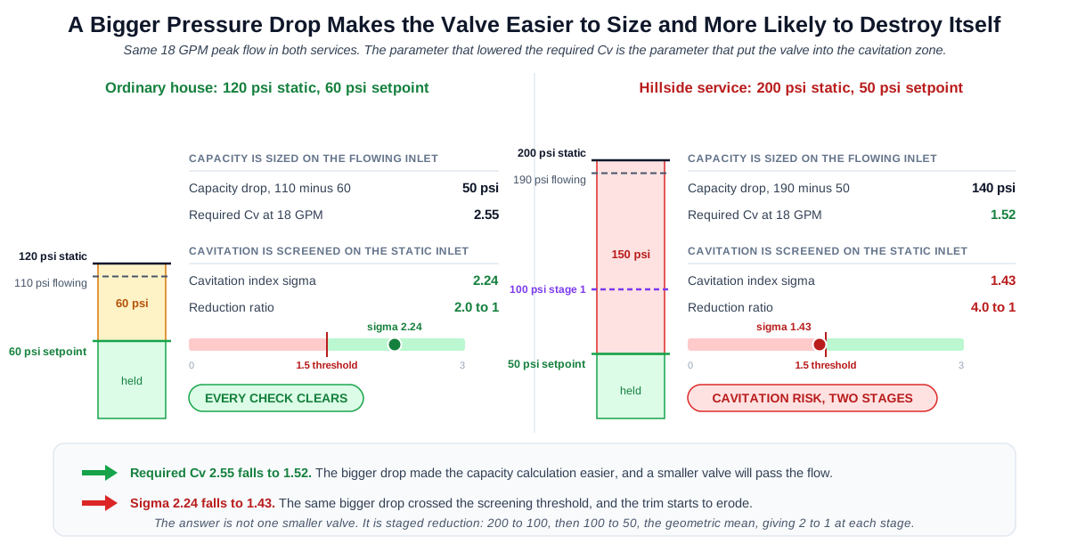
Given: the base of a high rise or a hillside service. Static inlet 200 psi, which is 1379 kPa. Inlet at peak flow 190 psi. Setpoint 50 psi, which is 344.8 kPa. Peak flow 18 GPM.
Step 1, capacity. The drop is 140 psi, so the required Cv is 1.52, lower than Example 1. On capacity alone this is an easier valve to find, and a smaller one will do.
Step 2, cavitation. Sigma is 1.43, at or below the 1.5 threshold, so the service is in the cavitation zone.
Step 3, ratio. 200 divided by 50 is 4 to 1, past the working maximum for a single valve.
Step 4, the remedy. The intermediate setpoint is the geometric mean of 200 and 50, which is 100 psi, or 690 kPa. That gives 2 to 1 at each stage, comfortably inside the range for both valves.
Result: staged reduction in two valves, not one smaller valve. Note what happened: the larger pressure drop made the capacity calculation more comfortable and put the installation into the zone where the trim erodes. A calculator returning only a required Cv gives its most confident answer here, and it is the wrong answer.
Example 4. The turndown no single valve can hold
Given: Example 1 inputs, plus a minimum overnight demand of 0.5 GPM, which is 1.89 L/min, from a single slow fixture.
Required Cv is 2.55 at peak and 0.071 at the minimum, so the demand turndown is 36 to 1.
Work down the ladder of candidate valves. Rated Cv 2.5 sits at 101.8 percent of rated at peak and fails capacity outright. Rated Cv 3.0 passes at 84.9 percent. Rated Cv 3.5 passes comfortably at 72.7 percent. Rated Cv 8.0 passes easily at 31.8 percent. Now look at the same four valves at the overnight minimum: 2.83, 2.36, 2.02 and 0.88 percent of rated. Every one is below the five percent screening threshold, and the number gets worse as the valve gets larger.
Result: the problem is the 36 to 1 turndown itself, not a badly chosen valve. Even the smallest valve that clears the capacity band, a rated Cv of about 3.0, still lands at 2.36 percent of rated overnight. No single valve on the ladder holds stable control across that span, so the remedy is the arrangement rather than the size: a small valve carrying low demand in parallel with a larger valve carrying peak. This failure is invisible at the peak operating point, which is the only point a plain Cv calculation looks at.
Standards & References
- ASSE 1003-23/CSA B356:23, Water Pressure Reducing Valves for Potable Water Distribution Systems The device standard for direct acting single diaphragm valves, the type found on most residential services. This is the first edition of the joint ASSE and CSA document and it supersedes ASSE 1003 published in 2020 and CSA B356 published in 2022. Scope covers reducing both static and flowing pressures.
- ASSE 1003-23/CSA B356:23, read-only access through the IAPMO codes library The full text of the device standard, readable without purchase, for confirming the scope and the performance requirements a listed valve has to meet.
- ASSE 1103-2024e1, Performance Requirements for Pilot Operated Water Pressure Reducing Valves for Potable Water The separate device standard for pilot operated diaphragm valves, usual on larger commercial and municipal services. Worth knowing because the codes cite ASSE 1003 for the residential case and a pilot operated valve is a different listing.
- ASSE 1017-2023, Temperature Actuated Mixing Valves for Hot Water Distribution Systems Named here to mark the boundary: mixing and tempering valves are a different device class and are not sized by this calculator.
- ISA RP75.23, Considerations for Evaluating Control Valve Cavitation The source of the sigma cavitation index used for the screening check on this page. The critical sigma for any particular valve depends on its style and its opening, and the manufacturer cavitation curve governs.
- ISA 75.01.01 and IEC 60534-2-1, Flow Equations for Sizing Control Valves The source of the liquid flow coefficient relationship. For water the specific gravity is 1.00, which is why the sizing relationship reduces to flow divided by the square root of the pressure drop.
- IPC Section 604.8 and IRC Section P2903.3.1, maximum water pressure Set the 80 psi ceiling on static pressure in the distribution piping and require an approved pressure reducing valve with a strainer above it. UPC Section 608.2 carries the parallel requirement.
- IPC Section 607.3, thermal expansion control Requires a thermal expansion control device wherever a storage water heater is supplied with cold water through a check valve, a pressure reducing valve or a backflow preventer, connected downstream of all such devices. UPC Section 608.3 carries the parallel requirement and permits a listed expansion tank or another approved device.
Units
Flow is entered in gallons per minute or litres per minute. Convert with 1 GPM equal to 3.785411784 L/min.
Pressure is entered and reported in pounds per square inch and kilopascals, with the equivalent in feet of head where useful. Convert with 1 psi equal to 6.895 kPa, and 1 psi equal to 2.31 feet of head. The 80 psi code ceiling is 552 kPa. A 60 psi setpoint is 414 kPa.
The flow coefficient stays as Cv in both unit systems, because that is how valves are catalogued. The metric equivalent is Kv, defined as cubic metres per hour at a drop of 1 bar, and Cv is approximately 1.156 times Kv. A required Cv of 2.55 corresponds to a Kv of about 2.20.
The cavitation index is dimensionless and requires absolute pressure. Absolute pressure is gauge pressure plus 14.7 psi, or plus 101.3 kPa. The Cv calculation may use gauge pressure because only the difference matters, and this is a common source of error when the two calculations are done side by side.
Water temperature is entered in degrees Fahrenheit or degrees Celsius, and 60 F is 15.6 C. The vapour pressure the cavitation index uses is reported in psia in both unit systems, because that is how steam tables list it.
The internal unit selector governs the fields, labels, math, on-screen result and any exported result, and it takes priority over any site-wide unit switch. Switching converts the values you entered rather than reinterpreting them, so 120 psi becomes 827.4 kPa and returns to exactly 120 psi when switched back. Every entry is stored internally in one fixed unit, GPM for flow, psi for pressure and degrees F for temperature, at full precision, and is converted only when it is drawn into a field. The figure on screen is rounded for legibility, the stored one is not, so the calculation always runs on what you entered and repeated switching never shifts a value.
Limitations
- Where the inlet pressure at peak flow is not entered, the calculator falls back to the static value and the result will tend to undersize the valve. The fallback is flagged on the result and is usable for a first pass, but the flowing figure should be confirmed before anything is ordered.
- This calculator screens a single stage of pressure reduction on potable water. It does not size thermostatic mixing valves, master mixing valves or other ASSE 1017 devices, and it does not size pressure relief valves or safety valves, which follow entirely different rules.
- The cavitation index here is a screening test, not a selection. The critical sigma at which a particular valve begins to cavitate depends on its style, its trim and how far it is open, and the manufacturer cavitation curve is the authoritative check. A result above the threshold is not a guarantee, and a result below it is a signal to look further rather than a final verdict.
- The stability thresholds, the 20 percent and 5 percent Cv utilization figures and the 20 to 1 turndown limit, are screening values drawn from control valve practice generally. A small residential direct acting regulator has different trim geometry from a globe control valve, so the manufacturer minimum controllable flow governs. Of the four, the turndown ratio is the most robust.
- Cv utilization is a fraction of rated capacity. It is not stem travel and not a percentage open, because the relationship between lift and flow is not linear.
- The reduction ratio guidance varies by source between 2 to 1 as comfortable, 2.5 to 1 as a conservative manufacturer limit and 3 to 1 as the working maximum. This page uses 3 to 1 as the staging trigger and 2.5 to 1 as a caution. Both are industry practice, not a code requirement.
- The minimum operating differential is device specific and there is no single published figure, so it is an optional input. Left blank, the calculator gives a manufacturer advisory rather than a false pass or fail.
- The temperature input adjusts the vapour pressure in the cavitation screen. Its effect is modest at ordinary domestic service pressures and becomes material for hot service or a low absolute inlet pressure. It does not make this a hot water calculator.
- The 80 psi code ceiling is applied at exactly 80 psi, which is 551.6 kPa. Code documents publish the metric figure as the rounded 552 kPa, so a setpoint entered as 552 kPa is 80.06 psi and raises the ceiling flag.
Common Mistakes to Avoid
- Treating a required Cv as a valve selection. The coefficient only proves the valve can pass peak flow at the drop available. It says nothing about low-flow stability, cavitation, the minimum operating differential, or the code consequences of installing the valve at all.
- Using one inlet pressure for the whole calculation. Capacity needs the lowest pressure available at peak flow and cavitation needs the highest static pressure. In the worked case on this page, using static for capacity undersizes the valve by 26 percent, and using flowing pressure for cavitation hides the worst case entirely.
- Sizing the valve to the pipe. The valve body size and the pipe size are separate decisions. A smaller body with the right Cv is often the better choice, and matching the pipe is not a sizing method.
- Checking only the peak operating point. The peak is where a plain Cv calculation is evaluated and it is the least likely check to fail. The failure that actually happens is at the other end of the range, overnight, when the valve is barely cracked open.
- Assuming a larger valve is the safer choice. It is the more common error. A larger valve works closer to its seat at every flow, which makes hunting worse and does nothing for cavitation.
- Trying to fix cavitation with a bigger valve. Cavitation is caused by the pressure ratio, not by capacity. The remedies are staged reduction, anti-cavitation trim, or moving the valve to a point with a smaller drop.
- Using gauge pressure in the cavitation index. Sigma requires absolute pressure. Using gauge pressure produces a number that looks plausible and is wrong, which is worse than an obvious error.
- Setting the valve higher than needed to cover uncertainty. Excess setpoint increases leakage, pipe stress and water loss, and can push the downstream side back above the code ceiling once thermal expansion is added.
- Forgetting the expansion tank. Installing the valve closes the system. Where a storage water heater is served, thermal expansion control is required by code, and its omission is among the most frequently cited failures at inspection.
- Reading the reduction ratio as a hard rule. The 3 to 1 figure is practice, not a standard, and the real limit for a given valve comes from its cavitation curve.
- Confusing a pressure reducing valve with a pressure relief valve. One holds a downstream pressure during normal operation. The other opens to protect against overpressure. They are sized by different methods and to different standards.
Frequently Asked Questions
What size pressure reducing valve do I need for a house?
Should the valve be the same size as the pipe?
Why does the calculator ask for two inlet pressures, and does a valve control flowing pressure or only static?
What is cavitation and how do I know if my valve will cavitate?
Can I fix cavitation by fitting a larger valve?
When do I need two valves in series?
Why does my pressure reducing valve hunt or make noise at night?
What pressure should a pressure reducing valve be set to?
What if I do not know the inlet pressure at peak flow?
Do I need an expansion tank if I install a pressure reducing valve?
Is a pressure reducing valve the same as a pressure relief valve?
Frequently Used Together
Engineers often use these calculators in combination for complete project workflows:
Related Calculators
Explore similar calculators that might be useful for your project:
Plumbing Quick Reference — Keep It On Your Phone On Site
A 10-page field reference for catching pressure, velocity, slope, and pump-sizing mistakes before you order pipe, close a wall, or add a booster.
- Velocity limits, fixture pressure minimums, drain slope, and the 80 psi ceiling in one table
- Worked examples that show why a single pressure number gives four different answers
- Keep it on your phone, or print the two field-check pages
Free PDF. Calculators stay free. Unsubscribe anytime.
Calculate
This selector governs every field, label, result and export on this page, and it takes priority over the site header switch. Switching converts the values you entered rather than reinterpreting them.
The inlet pressure at the valve with nothing running, which is the highest it will ever see. The cavitation index and the reduction ratio are screened on this figure, because it produces the largest drop the valve will ever be asked to make.
The inlet pressure at the valve while the system is passing peak demand, after the service line, the meter and upstream fittings have taken their share. The capacity calculation uses this figure. Left blank it falls back to the static value, which overstates the drop available and tends to undersize the valve, and the result says so.
The pressure the valve is to hold downstream. IPC 604.8, IRC P2903.3.1 and UPC 608.2 cap distribution pressure at 80 psi, which is 552 kPa, and common practice sets 60 to 70 psi to leave margin below it.
The maximum concurrent flow through the valve. A water supply fixture unit calculation is the usual source for this number.
Demand Range (Optional)
The smallest flow the valve will actually be asked to regulate, such as one slow fixture overnight. This is the point an oversized valve fails at, and it is invisible at peak. Enter the smallest real flowing demand rather than zero: a no-flow condition is not a controllable flow point.
The flow the system spends most of its working day at. It adds a third operating point to the required Cv, between the peak and the overnight minimum.
Candidate Valve (Optional)
The rated flow coefficient of a valve from a catalogue. Entering it turns the requirement into a verdict and unlocks the Cv utilization screening at peak and at minimum flow. Left blank, capacity and low-flow stability are reported as not evaluated rather than passed.
The margin applied to the calculated peak requirement to give a selection Cv. Left blank the calculator applies 25 percent, the common figure for a regulator, and the result says the default was used.
Wording only: it does not change any number. Direct acting single diaphragm valves are listed to ASSE 1003-23/CSA B356:23 and pilot operated valves to ASSE 1103. Pilot operated valves in particular need enough differential to drive the pilot circuit.
Service Conditions (Optional)
Sets the vapour pressure used in the cavitation index. Left blank the screen runs at 60 F, the temperature the flow coefficient itself is defined at, and the result says so. The effect is modest at ordinary domestic service pressures and becomes material for hot service or a low absolute inlet.
The working difference between inlet and setpoint the valve needs to regulate at all. The figure is device specific and there is no single published value, so left blank the calculator returns a manufacturer advisory rather than a false pass or fail.