Backflow Preventer Pressure Drop Calculator — RPZ and DCVA Loss, Minimum Pressure Loss, and Pressure Budget
On this page
Calculate
This selector governs every field, label, result and export on this page, and it takes priority over the site header switch. Switching converts the values you entered rather than reinterpreting them.
Reduced pressure assemblies are listed to ASSE 1013 and AWWA C511, double check assemblies to ASSE 1015 and AWWA C510. The four device classes marked as not modelled are named so you can see where this version stops: they return an out of scope result rather than a loss figure, because no verified curve stands behind one. This calculator does not decide which assembly you need, which is a hazard assessment governed by the code and the water purveyor.
Nominal assembly size, which stays in inches in both unit systems because that is how these assemblies are listed, ordered and approved. Verified published data is carried for a 3/4 in reduced pressure assembly and a 3 in double check assembly. For any other combination the calculator asks for the manufacturer minimum loss rather than printing an unverified figure as though it were data.
The flow the assembly has to pass. A water supply fixture unit calculation is the usual source for this number. Zero is not a design duty here: the zero flow case is the minimum loss, and it is reported on every result.
Low Demand (Optional)
The lowest flow the assembly will be asked to pass. Left blank it is taken as zero, which returns the spring floor exactly, and that is often the more revealing number because it is the pressure the assembly costs before anything is running.
Supply Pressure (Optional)
The static pressure upstream of the assembly with nothing running. It feeds the downstream pressure in the no-flow condition, against the spring floor. It is never used for the figure at design flow.
The pressure still available upstream of the assembly while the system is passing the design flow, after the service line, the meter and upstream fittings have taken their share. It feeds the downstream pressure at flow and the share of supply. It is never substituted by the static figure.
The pressure the budget allows this device, if one has been assigned. The calculated loss is tested against it and the result says by how much it clears or exceeds the allowance.
Manufacturer Data (Optional)
The minimum loss from the manufacturer chart, the figure at zero flow in the static test state. It replaces the representative floor, and for a size and type with no verified dataset it is what makes a result possible at all.
A loss read off the manufacturer chart at a specific flow. With the flow it was stated at, the estimate is fitted through your point instead of the representative one. A published loss below the minimum loss is rejected rather than fitted, because it would give a negative coefficient.
The flow the published loss belongs to. Both numbers must come from the same point on the chart: one without the other cannot be fitted.
Relief Discharge, Reduced Pressure Assemblies Only (Optional)
A test cock reading taken with a field test kit built to ASSE 1064. This is the quantity the relief valve actually watches, and it cannot be derived from the total loss across the assembly. Without it the relief check is reported as not evaluated rather than passed.
The differential at which the relief valve opens. Left blank the calculator uses 2 psi, the published relief opening point, and the result says so. The actual setting is device specific.
Closed System (Optional)
Wording only: it does not change any loss figure. Location decides which system the check function closes, which is why an assembly on an isolated irrigation branch does not necessarily close the domestic hot water system.
IPC Section 607.3 and UPC Section 608.3 require thermal expansion control where a storage water heater is supplied with cold water through a check valve, a pressure reducing valve or a backflow preventer. The requirement follows the water heater rather than the assembly on its own, so a definite answer here turns a conditional advisory into a definite one.
Overview
A backflow preventer is not just another fitting loss. Most pipe and meter losses approach zero as flow approaches zero, because they come from velocity. A spring loaded backflow assembly keeps a minimum pressure cost even at very low flow, because water has to push open two spring loaded check valves before it moves at all. The loss starts from a floor and climbs from there, and at ordinary domestic flows most of the cost is the floor rather than the flow.
This calculator returns what the assembly takes out of the supply: the loss at the flow you specify, the minimum loss set by the spring train, the pressure left downstream at rest and while flowing, and the share of the available pressure the device consumes. That figure is the line the water pressure calculation needs and currently has to be guessed at.
What the page does not do is choose the assembly for you. The hazard assessment and the water purveyor decide which type is required, and that is usually settled long before anyone asks about pressure. This calculator reports what the required assembly costs and whether the supply can afford it.
One more thing it will not do is pretend. The relief valve on a reduced pressure assembly watches the differential across the first check, not the total loss across the device, and the one cannot be derived from the other. Supply that differential from a test reading and the calculator checks it. Leave it out and the calculator says the check was not evaluated rather than inventing a number.
What to Look at First
The minimum loss, before you look at anything else. A reduced pressure assembly holds back pressure with nothing running at all, because water has to push open two spring loaded checks before it moves. Every other item in a pressure budget approaches zero loss as flow falls. This one does not, and a budget built from friction alone is short by that floor at every flow.
Which upstream pressure produced which answer. The downstream figure at rest comes from the static upstream pressure and the spring floor. The downstream figure at flow comes from the flowing upstream pressure and the full loss. They are two different numbers, and the calculator will not substitute one for the other: using the static value for both overstates what is left while the system is actually running.
The curve status line. Loss figures come from a representative published dataset unless you enter a point from the manufacturer chart, and two assemblies of the same size and type from different makers can differ enough to change whether a budget closes. The status sits in the top result block rather than in a footnote, because it tells you how much weight the number can carry.
The relief line, and what it does not say. The relief valve watches the differential across the first check, which is a different quantity from the total loss across the assembly and cannot be derived from it. Give the calculator a test cock reading and it checks the margin. Leave it out and it reports the check as not evaluated rather than passed.
How to Use This Calculator
Choose the unit system with the calculator's own selector. Every field, label, result and export follows that selector, and switching it converts the values you already entered rather than reinterpreting them.
Choose the assembly type. This version models reduced pressure assemblies, known as RPZ or RP, and double check valve assemblies, known as DCVA or DC. Other device classes are listed so you can see where the boundary is, and the calculator returns an out of scope result for them rather than a figure with no verified curve behind it.
Choose the assembly size and enter the design flow through it. A water supply fixture unit calculation is the usual source for the flow. Where no verified curve exists for that type and size, the calculator says so and asks for the manufacturer figures instead of inventing one.
Enter the minimum or standby flow if you want the loss at low demand. Left blank it is taken as zero, which returns the spring floor, and that is often the more revealing number.
Enter the upstream pressure. There are two fields because they are two different numbers: the static pressure with nothing running, and the pressure still available upstream while the system is passing design flow. Each one feeds a different output, and the calculator will not substitute one for the other.
Enter the allowable loss for this device if the pressure budget assigns one, and the calculator will test the result against it.
If you have the manufacturer loss chart, enter the minimum loss at zero flow, and a published loss with the flow it was stated at. The estimate is then fitted through your own point instead of the representative one. Published curves differ between makers, so this is worth doing whenever the budget is tight.
For a reduced pressure assembly, enter the differential across the first check if you have a test reading taken with a field test kit. That unlocks the relief discharge check. Without it the check is reported as not evaluated.
Read the loss at design flow, the minimum loss, the downstream pressures, the budget share, the curve status, and the flags for the budget, the relief and the closed system consequence.
Only the assembly type, the size and the design flow are required, and no optional field blocks the Calculate button. Blank and an explicit zero are different states: a blank minimum flow is taken as zero and reported as the spring floor case, while a blank upstream pressure leaves the downstream figures reported as not evaluated rather than passed.
Inputs & Outputs
Inputs
Outputs
Backflow Preventer Pressure Drop Formula
The loss has two parts. A floor set by the check springs, which is there before any water moves, and a term that grows with flow. It is not the square law that describes a water meter.
- Loss at flow: loss_design = static_floor + b times the square root of q_gpm
- Minimum loss: at zero flow the loss equals static_floor exactly
- Coefficient from a maker point: b = (published_loss_psi - static_floor) divided by the square root of published_at_gpm
- Downstream at the static condition: p_down_static = upstream_static_psi - static_floor
- Downstream at flow: p_down_flowing = upstream_flowing_psi - loss_design
- Share of supply: share = loss_design divided by upstream_flowing_psi
- Relief margin: relief_margin = first_check_diff_psi - relief_threshold_psi
The square root form is fitted to published datasets for small assemblies and reproduces them closely. It is an estimate inside the range of that data, not a general law. A published 6 in reduced pressure assembly loses 12.0 psi at 140 GPM and 9.5 psi at 840 GPM, so on larger assemblies at high flow the curve can fall rather than rise.
The calculator uses a fixed model. Values are stored at full precision in one canonical unit and rounded only for display, so switching unit systems and back returns the numbers you entered.
INPUTS
- assembly_type: RPZ or DCVA. Required.
- size_in: nominal assembly size. Required.
- q_gpm: design flow through the assembly. Required.
- q_min_gpm: minimum or standby flow. Optional, default 0.
- upstream_static_psi: pressure upstream at no flow. Optional.
- upstream_flowing_psi: pressure upstream at design flow. Optional.
- allowable_loss_psi: budget allowed for this device. Optional.
- published_static_psi: minimum loss from the maker chart. Optional.
- published_loss_psi: maker loss at a stated flow. Optional.
- published_at_gpm: the flow that loss was stated at. Optional.
- first_check_diff_psi: differential across check one. Optional, RPZ only.
- relief_threshold_psi: relief opening point. Optional, default 2.
- location and heater_downstream: wording only, no effect on any loss figure.
FORMULA BLOCK START

GUARDS
  IF assembly_type, size_in or q_gpm is blank        THEN INCOMPLETE
  IF the type is a vacuum breaker, a dual check
     or a detector assembly                          THEN OUT OF SCOPE,
     no loss figure is returned for a device class with no verified curve
  IF any entered value is negative                   THEN OUT OF RANGE
  IF q_gpm is at or below zero                       THEN OUT OF RANGE,
     zero flow is the minimum loss case, not a design duty
  IF no verified floor exists for that type and size
     and published_static_psi is blank               THEN CURVE NOT VERIFIED
  IF published_loss_psi is below the floor           THEN the point is not
     fitted: the coefficient would be negative. The representative curve is
     used instead and the result says why
  IF published_loss_psi or published_at_gpm is
     entered alone, or published_at_gpm is at or
     below zero                                      THEN the point is not fitted
  IF neither upstream pressure is entered            THEN the downstream figures
     and the share of supply read NOT EVALUATED, never passed
  IF only one upstream pressure is entered           THEN only the output it
     supports is produced. One is never substituted for the other
  IF the assembly is not a reduced pressure assembly THEN the relief check reads
     NOT APPLICABLE, never passed
  IF first_check_diff_psi is blank                   THEN the relief check reads
     NOT EVALUATED. It is never inferred from the total loss
  IF q_min_gpm is above q_gpm                        THEN warn, the design flow
     is understated

MINIMUM LOSS, the spring floor that is there before any water moves
  IF published_static_psi is entered
     static_floor = published_static_psi                    MANUFACTURER FLOOR
  ELSE
     static_floor = the verified floor for that type and size
                                                            REPRESENTATIVE CURVE
  verified floors    3/4 in reduced pressure    8.0 psi
                     3 in double check          4.0 psi
  it is check spring tension rather than friction, so it is present at zero flow
  where no verified floor exists for the selected type and size and none was
  entered, no figure is returned at all rather than an unverified one

MANUFACTURER POINT OVERRIDE
  IF published_loss_psi and published_at_gpm are both entered
     AND published_at_gpm is above zero
     AND published_loss_psi is at or above static_floor
       b = (published_loss_psi - static_floor) / square root of published_at_gpm
                                                     MANUFACTURER POINT FITTED
  ELSE
       b = the coefficient of the representative dataset for that type and size
                                                     REPRESENTATIVE CURVE
  representative coefficients are derived from the published anchor points
  rather than typed in, so those points reproduce exactly:
       b = (anchor loss - static_floor) / square root of the anchor flow
  a single fitted point improves the estimate. It does not reproduce the full
  product curve, because the shape between points belongs to the product

LOSS AT FLOW, a floor plus a square root term, not the square law of a meter
  loss_design = static_floor + b multiplied by the square root of q_gpm
  loss_min    = static_floor + b multiplied by the square root of q_min_gpm
  q_min_gpm blank is taken as zero, where loss_min equals static_floor exactly
  IF q_gpm is past the flow range the dataset was checked against
     THEN the figure is an extrapolation rather than a fitted estimate
  IF the assembly is a double check
     THEN loss_design is reported against the 10 psi maximum loss permitted
     through a double check assembly, a device requirement on the listed
     product rather than a project budget

DOWNSTREAM PRESSURE, each figure from its own upstream pressure
  p_down_static  = upstream_static_psi - static_floor
  p_down_flowing = upstream_flowing_psi - loss_design
  the static figure never uses the flowing pressure, and the flowing figure
  never uses the static one
  IF either result is at or below zero THEN it reads None remaining and the
  shortfall is reported as a positive deficit, never as a negative pressure

BUDGET SHARE, screening bands, a presentation choice and not a code limit
  computed only where upstream_flowing_psi is above zero
  share = loss_design / upstream_flowing_psi
  share at or below 0.15                    MODEST
  share above 0.15 and at or below 0.30     SIGNIFICANT
  share above 0.30                          DOMINANT
  no flowing upstream pressure entered      NOT EVALUATED

BUDGET TEST, only when allowable_loss_psi is entered
  IF loss_design is above allowable_loss_psi THEN LOSS OVER BUDGET
  ELSE                                            WITHIN ALLOWANCE
  an assembly can be operating well inside its own rating and still not fit
  the budget it was given: what fails here is the budget, not the device

RELIEF DISCHARGE, reduced pressure assemblies only
  the relief watches the differential across the first check, which is a
  different quantity from the total loss and is never derived from it
  relief_threshold_psi blank is taken as 2 psi, the published opening point
  relief_margin = first_check_diff_psi - relief_threshold_psi
  relief_margin at or below zero            RELIEF DISCHARGE RISK
  relief_margin above zero                  MARGIN ABOVE THE RELIEF SETTING
  IF first_check_diff_psi is below 5 psi while the margin is still positive
     THEN raise FIRST CHECK BELOW THE FIELD TEST CRITERION. The AWWA field
     test criteria ask the first check to hold at least 5 psi, which keeps a
     buffer of at least 3 psi above the relief opening point

CLOSED SYSTEM
  IF a storage water heater is served downstream
     THEN THERMAL EXPANSION CONTROL REQUIRED, IPC 607.3 and UPC 608.3
  IF that was not stated
     THEN ADVISORY, HEATER NOT STATED
  ELSE NO REQUIREMENT FROM THIS DEVICE
  the check function closes the branch either way. The requirement follows the
  water heater, not the assembly on its own
  location and heater_downstream change the wording only, never a loss figure

UNIT CONVERSIONS
  L/min = GPM multiplied by 3.785411784
  kPa   = psi multiplied by 6.895
  feet of head = psi multiplied by 2.31, taken from the psi figure as displayed,
                 so the same loss reads the same feet of head in both unit
                 systems
  every entry is held internally in GPM and psi at full precision and is
  converted only when it is drawn into a field, so the math never works from
  a rounded figure and a unit switch never changes what you entered

FORMULA BLOCK END
RPZ vs Double Check Pressure Loss
The reduced pressure assembly costs more pressure than the double check, and the difference is not marginal. It is the price of the higher level of protection, and it is built into the hardware rather than into the sizing.
Both assemblies carry two independently acting check valves. The reduced pressure assembly adds a relief valve between them and, more importantly for pressure, a much heavier first check spring. The first check in a reduced pressure assembly is held closed by a spring of about 5 psi so that it can maintain a buffer above the relief opening point. A double check has no relief to protect, so its springs need only hold the check shut: the standard requires each to be at least 1 psi, and manufacturers keep them near 1.5 psi precisely because the assembly is used where pressure loss matters, such as fire service.
The published figures make the gap concrete. A representative 3/4 in reduced pressure assembly has a minimum loss of about 8.0 psi, which is 55.2 kPa. A representative 3 in double check assembly has a minimum loss of about 4.0 psi, which is 27.6 kPa. Half the loss on an assembly four times the nominal size. At flow the gap widens in practical terms: the 3 in double check is still near 5.0 psi at 150 GPM, while the small reduced pressure assembly has passed 12 psi by 20 GPM.
AWWA also caps the two differently in practice. The maximum loss through a double check assembly is not permitted to exceed 10 psi, and a double check is rated to a maximum working pressure of 175 psi over a 34 F to 180 F range.
None of this is a reason to fit a double check where a reduced pressure assembly is required. The hazard decides. A reduced pressure assembly protects against high hazard contamination, and a double check is only permitted where the assessment says a pollutant rather than a contaminant is involved. The comparison on this page exists so you know what the required assembly costs, and for the narrower case where the assessment genuinely permits either.
Backflow Preventer Pressure Loss by Flow and Size
Loss through a backflow assembly depends on the type, the nominal size, the flow through it and, more than anything else, the specific product. Two assemblies of the same size and type from different makers can differ enough to change whether a pressure budget closes.
For the representative 3/4 in reduced pressure assembly this page is anchored on, the published figures run from about 8.0 psi at zero flow, through 10.25 psi at 5 GPM, to 12.5 psi at 20 GPM, and about 14.4 psi at 40 GPM. In metric that is 55.2, 70.7, 86.2 and 99.0 kPa, at 0, 18.9, 75.7 and 151.4 L/min. Notice how flat that is: doubling the flow from 20 to 40 GPM adds under two psi, because the checks open further as flow rises and the flow area grows with them.
That flatness has a limit, and it is worth knowing where the model stops being safe. On larger assemblies the curve can actually turn over. One published example gives a 6 in reduced pressure assembly at 12.0 psi at 140 GPM and 9.5 psi at 840 GPM: six times the flow, and the loss falls. No simple rising formula reproduces that, including the one this calculator uses. The square root form fits the small assembly dataset it was built from and should be treated as an estimate inside that range, not as a general law of backflow assemblies.
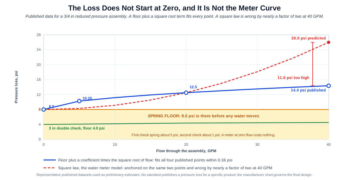
Which is why the manufacturer chart is not a nicety. Standards define what the device must do to be listed; none of them publish a pressure loss for a specific product. Where the budget is tight, get the loss curve for the assembly you are actually installing. If you have one published point, enter it here and the estimate is fitted through your figure and the verified floor. That is better than the generic curve and it is still not the full product curve, because the real shape between points is the manufacturer's to describe, not ours to infer.
Why a Reduced Pressure Assembly Has a Minimum Pressure Loss
In a pipe, a fitting or a water meter, pressure loss comes from velocity. Slow the water down and the loss falls away with it. Stop the water and the loss is nothing at all.
A backflow assembly does not work that way, because the resistance is mechanical rather than frictional. Water arriving at a reduced pressure assembly meets a check valve held shut by a spring of roughly 5 pounds, and behind it a second check held by about 1 pound. Nothing moves until that spring resistance is overcome, and the springs do not care how much water is being asked for. The resistance is the same whether the building is drawing forty gallons a minute or barely anything.
That is why the loss curve has a floor. The published figure for the representative 3/4 in reduced pressure assembly in the dataset this page uses is at least 8.0 psi, which is 55.2 kPa, measured in the static test state at zero flow. In the same dataset a 3 in double check assembly sits at about 4.0 psi, or 27.6 kPa, because its springs only need to hold the checks closed rather than maintain a buffer above a relief valve.
Two cautions about that number. It belongs to a representative published dataset for one size and construction, not to every assembly with that label on it, and the actual figure for a product comes from its own chart. And the static test state is a specific measurement condition, the one a certified tester uses because the checks are closed drip tight at zero flow, rather than a promise about what any gauge downstream will read after a long period with nothing running.
What is reliably true, and what matters for design, is that the loss does not begin at zero. A pressure budget assembled from friction alone is short by that floor at every flow, and short by nearly all of it at low demand.
Backflow Relief Valve Discharge Check
The relief valve is the part of a reduced pressure assembly that most often brings someone out to look at it, because when it opens it discharges water to the drain and that looks like a failure.
What it is actually doing is watching one number continuously: the pressure difference across the first check valve. The AWWA field test criteria give the design intent precisely. The first check must hold at least 5 psi of differential, which maintains a buffer of at least 3 psi above the relief opening point, and the relief must open at no less than 2 psi of differential between the supply and the intermediate zone. When that differential collapses toward 2 psi, the relief opens and dumps the zone rather than risk water moving backward.
The differential across the first check is not the total loss across the assembly, and it cannot be worked out from it. They are different measurements: the total loss is what the whole device costs the system, while the first check differential is an internal pressure relationship read at a test cock with a field test kit built to ASSE 1064. This calculator will check the margin when you give it that reading, and will report the check as not evaluated when you do not. It will not infer it.
As for the cause, a discharging relief often means the supply sagged: a large draw elsewhere, a main break, a partly closed upstream valve, or an assembly undersized for the flow so that the pressure drop across it eats into the differential. But persistent or unexplained discharge can equally mean debris under a check, a fouled or damaged check valve, a relief valve problem, or an installation fault. The honest answer is that the symptom points at pressure first and the device second, and that a field test settles which. Do not condemn the assembly before measuring, and do not dismiss a discharge that will not stop.
What Is Backflow Preventer Pressure Drop
A backflow prevention assembly stops water in the building from travelling back into the public main. A reduced pressure assembly does it with two independently acting check valves, each held closed by its own spring, separated by an intermediate chamber with a relief valve that vents that chamber to atmosphere. A double check assembly has the two checks without the relief.
The springs are the whole reason this device costs pressure differently from everything else in the system, and the reason its loss curve has a floor rather than starting at zero.
That gives the curve a shape with two parts: a floor set by the spring train, and a rise that grows with flow as the checks are pushed further open. The rise is gentler than most people expect, precisely because pushing the checks further open increases the flow area at the same time as it increases the flow, and on large assemblies at high flow the curve can even turn back down.
The relief valve adds a behaviour rather than a loss. It watches the pressure difference across the first check continuously, and opens when that difference falls to around two pounds.
Key Facts
- A reduced pressure assembly has a minimum pressure loss from its check springs. In the representative dataset used here, a 3/4 in assembly shows at least 8.0 psi, which is 55.2 kPa, in the static test state at zero flow.
- The same representative 3/4 in assembly shows about 12.5 psi, which is 86.2 kPa, at 20 GPM or 75.7 L/min, and about 14.4 psi, which is 99.0 kPa, at 40 GPM.
- In the same dataset a 3 in double check assembly shows about 4.0 psi, which is 27.6 kPa, at zero flow and about 5.0 psi, or 34.5 kPa, at 150 GPM.
- The loss curve is not a square law. Fitting one to the reduced pressure points predicts 26.0 psi at 40 GPM against a published figure near 14. A floor plus a square root term reproduces those points within 0.36 psi.
- The curve is not always rising either. A published 6 in reduced pressure assembly gives 12.0 psi at 140 GPM and 9.5 psi at 840 GPM, so no simple formula covers the full range and the manufacturer chart governs.
- The first check valve in a reduced pressure assembly is held closed by a spring of about 5 psi and the second by about 1 psi. In a double check assembly each check spring must be at least 1 psi, and makers keep them near 1.5 psi to hold loss down.
- AWWA field test criteria: the first check must hold at least 5 psi differential, maintaining a buffer of at least 3 psi above the relief opening, and the relief must open at no less than 2 psi differential. Each check in a double check assembly must hold tight at 1.0 psid or greater.
- The maximum loss through a double check assembly must not exceed 10 psi, which is 68.9 kPa. A double check is rated to 175 psi maximum working pressure over 34 F to 180 F.
- Under AWWA C511 a reduced pressure assembly must withstand at least 150 psi, which is 1034 kPa, and cold water assemblies are designed for 33 F to 140 F, or 1 C to 60 C.
- A reduced pressure assembly must not be installed in a pit and its relief must never be submerged, because the relief discharges to atmosphere through an air gap. A double check does not carry that restriction.
- A reduced pressure assembly must not be installed vertically unless specifically tested and approved for that orientation.
- Any check function makes the downstream system closed. IPC Section 607.3 and UPC Section 608.3 require thermal expansion control where a storage water heater is supplied through a check valve, a pressure reducing valve or a backflow preventer.
- The 2021 revision of the reduced pressure and double check standards removed the double check fire protection category, because no manufacturer produced that low loss assembly. Fire service uses ASSE 1047 or ASSE 1048 detector assemblies.
- Standards define device performance and listing. None of them publish a pressure loss figure for a specific product; loss curves are manufacturer data.
Applications
- A designer building a pressure budget needs a number for the backflow line and has nowhere to get one. This page produces it, and the budget is assembled on the water pressure page.
- A contractor investigating low pressure in a building with a reduced pressure assembly checks how much of the missing pressure is the assembly, and specifically how much of it is present even at low demand.
- A service technician called out to an assembly that is discharging water uses the relief section to understand what the relief actually measures, and to see that a field test rather than a guess settles whether the cause is supply or device.
- An engineer comparing a marginal supply against a required assembly checks whether the pressure left downstream still supports the system, and hands the figure to the booster pump calculation if it does not.
- A designer comparing two manufacturer charts for the same nominal size and type finds that the product choice alone decides whether the pressure budget closes, which is the case for entering a published point rather than accepting a generic figure.
- A plans reviewer checks that the loss assumed in a submitted pressure calculation is consistent with the assembly actually specified, and that manufacturer data was used where the margin is tight.
Example Calculations
Example 1. What the assembly costs before anything is running
Given: a 3/4 in reduced pressure assembly from the representative dataset. Minimum flow left blank, so zero.
The loss is the spring floor, at least 8.0 psi, which is 55.2 kPa or 18.5 feet of head. There is no flow, no velocity and no friction, and the assembly is still holding back that much pressure, because the check springs have to be overcome before water moves at all.
Result: this is the number that separates a backflow assembly from every other device in the budget. A meter at zero flow costs nothing. This costs 8 psi.
Example 2. The same assembly under load
Given: the same assembly at 20 GPM, which is 75.7 L/min.
The loss is about 12.5 psi, which is 86.2 kPa or 28.9 feet of head. Of that, 8.0 psi is the floor and only about 4.5 psi came from the flow. At 40 GPM, which is 151.4 L/min, the loss is about 14.4 psi. Doubling the flow from 20 to 40 added under two psi.
Result: the curve is flat compared with what most people expect, because the checks open further as flow rises and the flow area grows with them. Most of the cost is the floor.
Example 3. Why the meter model is the wrong model
Given: the same two anchor points, 8.0 psi at zero flow and 12.5 psi at 20 GPM.
A water meter loses pressure by a square law, so doubling flow roughly quadruples loss. Fit that shape to these points and it predicts 26.0 psi at 40 GPM. The published figure is about 14.4 psi.
Result: the square law is wrong here by nearly a factor of two, and it errs high, which sends a designer looking for a booster pump that the system does not need.
Example 4. Reduced pressure against double check
Given: the representative datasets for both. A 3/4 in reduced pressure assembly and a 3 in double check assembly, each at zero flow and then at their published flow points.
At zero flow the reduced pressure assembly is at 8.0 psi, or 55.2 kPa, and the double check at 4.0 psi, or 27.6 kPa. At flow the reduced pressure assembly reaches 12.5 psi by 20 GPM, while the double check is still at 5.0 psi, or 34.5 kPa, at 150 GPM.
Result: the double check costs a fraction of the pressure, on a considerably larger assembly. That difference is the price of the relief valve and the heavier first check spring, which is to say the price of protection against a contaminant rather than a pollutant. It is information about cost, not a licence to substitute. The hazard assessment decides which assembly is permitted.
Example 5. The pressure budget, with two upstream figures
Given: upstream static 60 psi, which is 413.7 kPa. Upstream at design flow 50 psi, which is 344.8 kPa. A 3/4 in reduced pressure assembly at 20 GPM, so a design loss of 12.5 psi.
Downstream at the static condition: 60 minus the 8.0 psi floor leaves 52.0 psi, which is 358.5 kPa.
Downstream at design flow: 50 minus 12.5 leaves 37.5 psi, which is 258.6 kPa.
Share of the flowing upstream pressure: 12.5 divided by 50 is 25 percent, a significant share.
Result: two upstream numbers, two downstream answers, and neither one substitutes for the other. Using the static figure for both would overstate what is available at flow by ten psi.
Example 6. Inside its rating and over the budget
Given: the same assembly and duty, with the project assigning an allowable device loss of 8 psi, which is 55.2 kPa.
The calculated loss is 12.5 psi against an allowance of 8. The result is over budget.
Result: note what has and has not happened. The assembly is operating perfectly well within its own rated range; nothing about the device is wrong. What has failed is the budget, which means either the allowance was set without accounting for the spring floor, or a larger assembly with a lower loss at this flow is needed, or the pressure has to come from somewhere else. A device can be entirely healthy and still not fit the design.
Example 7. Where the expansion requirement does and does not follow
Given, case A: the assembly sits on the building service, and a storage water heater is served downstream. The check function closes the system, water expanding as it heats has nowhere to return to, and thermal expansion control is required under IPC Section 607.3 and UPC Section 608.3.
Given, case B: the assembly sits on an isolated irrigation branch with no water heater downstream of it. The branch is closed, but the domestic hot water system is not affected by this device, so no thermal expansion requirement follows from it.
Result: the requirement follows the water heater, not the assembly on its own. Where a pressure reducing valve is also present on the same service, the requirement exists once, not twice.
Standards & References
- ASSE 1013-2021, Performance Requirements for Reduced Pressure Principle Backflow Prevention Assemblies The device standard for reduced pressure assemblies, revised in 2021 from the previous edition. It describes two independently acting check valves, internally force loaded to a normally closed position, separated by an intermediate zone with a hydraulically operated relief means force loaded to a normally open position. Read-only access through the IAPMO codes library.
- ASSE 1015-2021, Performance Requirements for Double Check Backflow Prevention Assemblies The device standard for double check valve assemblies. The 2021 revision removed the double check fire protection category, because no manufacturer produced that low loss assembly; fire service now uses detector assemblies under ASSE 1047 and ASSE 1048. Read-only access through the IAPMO codes library.
- ASSE International, product standards overview The scope statement for each ASSE product standard, including 1020 for pressure vacuum breakers, 1024 for dual check devices, 1047 and 1048 for detector assemblies, 1056 for spill resistant vacuum breakers, and 1064 for the backflow prevention assembly field test kits the first check differential is read with.
- ANSI/AWWA C511, Reduced-Pressure Principle Backflow Prevention Assembly Sets the device envelope used on this page: a working water pressure of at least 150 psi, which is 1034 kPa, without damage or impairment of function, and a cold water design range of at least 33 F to 140 F, which is 1 C to 60 C. A complete assembly is a hydraulically dependent relief valve between two independently operating internally loaded check valves, between two resilient seated shutoff valves, with four test cocks.
- ANSI/AWWA C510, Double Check Valve Backflow Prevention Assembly The parallel AWWA standard for double check assemblies, which carries the maximum working pressure and the loss limit quoted on this page.
- AWWA Manual M14, Backflow Prevention and Cross-Connection Control The source of the field test criteria quoted on this page: the first check holding at least 5 psi differential, the relief opening at no less than 2 psi differential, and each double check valve holding tight at 1.0 psid or greater.
- IPC Section 608 and Section 607.3, backflow protection and thermal expansion control IPC Section 608 lists the assembly types and the standards each must conform to. IPC Section 607.3 requires thermal expansion control where a storage water heater is supplied with cold water through a check valve, a pressure reducing valve or a backflow preventer, installed downstream of all of them.
- UPC Section 608.3, thermal expansion control The Uniform Plumbing Code carries the parallel requirement to IPC Section 607.3. Where a pressure reducing valve is also present on the same service the requirement is raised once, not twice, and the tank is sized with the Expansion Tank Sizing calculator.
- Attribution note on the loss figures The code sections decide which assembly is required and the ASSE and AWWA standards define what the device must do to be listed. Neither publishes a pressure loss figure for a specific product. The loss values on this page are representative figures from published datasets, used as preliminary estimates. For final design the manufacturer loss curve for the actual assembly governs.
Units
Flow is entered in gallons per minute or litres per minute. Convert with 1 GPM equal to 3.785411784 L/min.
Pressure is entered and reported in pounds per square inch and kilopascals, with the equivalent in feet of head. Convert with 1 psi equal to 6.895 kPa, and 1 psi equal to 2.31 feet of head. A floor of 8.0 psi is 55.2 kPa or 18.5 feet. A loss of 12.5 psi is 86.2 kPa or 28.9 feet.
Assembly sizes stay in inches in both unit systems, because that is how they are listed, ordered and approved wherever these standards apply.
The relief threshold of about 2 psi is 13.8 kPa, and the 5 psi first check criterion is 34.5 kPa. The AWWA working pressure requirement of 150 psi is 1034 kPa, and the 10 psi double check loss cap is 68.9 kPa.
The internal unit selector governs the fields, labels, math, on-screen result and any exported result, and it takes priority over any site-wide unit switch. Switching converts the values you entered rather than reinterpreting them, so 50 psi becomes 344.8 kPa and returns to exactly 50 psi when switched back.
Limitations
- This version models reduced pressure assemblies and double check valve assemblies only, and only for the sizes where a loss curve has been verified. Pressure vacuum breakers, spill resistant vacuum breakers, dual check devices and detector assemblies for fire service are named on the page but return an out of scope result rather than a number, because their curves are not verified and, in the case of vacuum breakers, because critical level and installation height rules govern their use as much as pressure does.
- Verified published data is carried for a 3/4 in reduced pressure assembly and a 3 in double check assembly. For any other size and type the calculator asks for the manufacturer minimum loss and returns no figure without it, rather than scaling an unverified estimate from a size it does have.
- The loss model has a range of validity. The square root form is fitted to published datasets for small assemblies and reproduces them closely, but it is not a general law. A published 6 in reduced pressure assembly loses 12.0 psi at 140 GPM and 9.5 psi at 840 GPM, so on larger assemblies at high flow the curve can fall rather than rise. Treat the calculated figure as an estimate within the range of the dataset behind it and use the manufacturer chart beyond that.
- The loss figures are representative values from published datasets, not standard requirements and not product data. No standard publishes a pressure loss for a specific product. Where the budget is tight the manufacturer curve for the actual assembly should replace the representative one.
- Entering one published point improves the estimate but does not import the manufacturer curve. The shape between points belongs to the product, and a single point plus a floor cannot describe it. For final selection use the full chart.
- The relief discharge check requires the differential across the first check valve, read at a test cock with a field test kit. It cannot be derived from the total loss across the assembly, and where it is absent the check is reported as not evaluated rather than passed. A relief that discharges persistently needs a field test, because debris, a fouled or damaged check and an installation fault produce the same symptom as a pressure sag.
- The budget share labels of modest, significant and dominant are a presentation choice made to give the result a shape. They are screening labels, not code limits.
- This calculator does not select the assembly. Hazard assessment under the code and the rules of the water purveyor decide which type is required. The comparison between the two modelled types is pressure information only and must not be used to justify a lower level of protection than the hazard requires.
- The page reports pressure at the assembly. It does not check pressure at the worst fixture, which needs elevation, downstream friction and the other device losses. Take the loss figure from here into the water pressure calculation for that.
- The thermal expansion requirement follows the storage water heater rather than the assembly alone.
Common Mistakes to Avoid
- Treating a backflow assembly as an ordinary fitting loss. It is the one device in the service whose loss does not fall away toward zero at low flow, because the check springs have to be overcome before any water moves. A budget built from friction alone is short by that floor.
- Using a square law for the loss curve. That is the correct model for a water meter and the wrong one here. Anchored on the same points it overstates the loss at 40 GPM by nearly a factor of two, in the direction that buys an unnecessary booster pump.
- Assuming the loss always rises with flow. On larger assemblies it can fall: one published 6 in reduced pressure assembly loses less at 840 GPM than at 140. Extrapolating any formula past the data behind it is guesswork.
- Treating one manufacturer point as the complete product curve. A single published point improves the estimate, but it does not describe the shape between points across the full flow range. Use the full chart for final selection.
- Using one upstream pressure for everything. The static figure and the pressure still available at design flow are different numbers, and each feeds a different output.
- Assuming a discharging relief means a broken assembly, or assuming it never does. A sagging supply and a fouled check produce the same symptom. Measure the first check differential and test before deciding.
- Trying to calculate relief discharge from the total loss. The relief watches the differential across the first check only. That is a different quantity and the total cannot produce it.
- Using the pressure comparison to pick a cheaper assembly. The hazard assessment decides the type. Comparing a reduced pressure assembly against a double check is useful only where the assessment already permits either.
- Forgetting the expansion tank. A check function closes the system, and where a storage water heater is served downstream, thermal expansion control is required by code.
- Checking the pressure at the assembly and calling it done. What matters is the pressure that survives to the worst fixture after elevation, friction and every other device.
- Assuming an assembly can go in a pit. A reduced pressure assembly must not, because its relief has to discharge to atmosphere and must never be submerged.
Frequently Asked Questions
How much pressure does a backflow preventer take?
Why does a backflow preventer lose pressure even at very low flow?
Which loses more pressure, an RPZ or a double check?
Why is water pouring out of my backflow preventer?
Can I calculate the loss from the pipe size?
Does a backflow preventer require an expansion tank?
Why does the calculator ask for both static and flowing upstream pressure?
Is the pressure loss shown here an AWWA or ASSE requirement?
Frequently Used Together
Engineers often use these calculators in combination for complete project workflows:
Related Calculators
Explore similar calculators that might be useful for your project:
Plumbing Quick Reference — Keep It On Your Phone On Site
A 10-page field reference for catching pressure, velocity, slope, and pump-sizing mistakes before you order pipe, close a wall, or add a booster.
- Velocity limits, fixture pressure minimums, drain slope, and the 80 psi ceiling in one table
- Worked examples that show why a single pressure number gives four different answers
- Keep it on your phone, or print the two field-check pages
Free PDF. Calculators stay free. Unsubscribe anytime.
Calculate
This selector governs every field, label, result and export on this page, and it takes priority over the site header switch. Switching converts the values you entered rather than reinterpreting them.
Reduced pressure assemblies are listed to ASSE 1013 and AWWA C511, double check assemblies to ASSE 1015 and AWWA C510. The four device classes marked as not modelled are named so you can see where this version stops: they return an out of scope result rather than a loss figure, because no verified curve stands behind one. This calculator does not decide which assembly you need, which is a hazard assessment governed by the code and the water purveyor.
Nominal assembly size, which stays in inches in both unit systems because that is how these assemblies are listed, ordered and approved. Verified published data is carried for a 3/4 in reduced pressure assembly and a 3 in double check assembly. For any other combination the calculator asks for the manufacturer minimum loss rather than printing an unverified figure as though it were data.
The flow the assembly has to pass. A water supply fixture unit calculation is the usual source for this number. Zero is not a design duty here: the zero flow case is the minimum loss, and it is reported on every result.
Low Demand (Optional)
The lowest flow the assembly will be asked to pass. Left blank it is taken as zero, which returns the spring floor exactly, and that is often the more revealing number because it is the pressure the assembly costs before anything is running.
Supply Pressure (Optional)
The static pressure upstream of the assembly with nothing running. It feeds the downstream pressure in the no-flow condition, against the spring floor. It is never used for the figure at design flow.
The pressure still available upstream of the assembly while the system is passing the design flow, after the service line, the meter and upstream fittings have taken their share. It feeds the downstream pressure at flow and the share of supply. It is never substituted by the static figure.
The pressure the budget allows this device, if one has been assigned. The calculated loss is tested against it and the result says by how much it clears or exceeds the allowance.
Manufacturer Data (Optional)
The minimum loss from the manufacturer chart, the figure at zero flow in the static test state. It replaces the representative floor, and for a size and type with no verified dataset it is what makes a result possible at all.
A loss read off the manufacturer chart at a specific flow. With the flow it was stated at, the estimate is fitted through your point instead of the representative one. A published loss below the minimum loss is rejected rather than fitted, because it would give a negative coefficient.
The flow the published loss belongs to. Both numbers must come from the same point on the chart: one without the other cannot be fitted.
Relief Discharge, Reduced Pressure Assemblies Only (Optional)
A test cock reading taken with a field test kit built to ASSE 1064. This is the quantity the relief valve actually watches, and it cannot be derived from the total loss across the assembly. Without it the relief check is reported as not evaluated rather than passed.
The differential at which the relief valve opens. Left blank the calculator uses 2 psi, the published relief opening point, and the result says so. The actual setting is device specific.
Closed System (Optional)
Wording only: it does not change any loss figure. Location decides which system the check function closes, which is why an assembly on an isolated irrigation branch does not necessarily close the domestic hot water system.
IPC Section 607.3 and UPC Section 608.3 require thermal expansion control where a storage water heater is supplied with cold water through a check valve, a pressure reducing valve or a backflow preventer. The requirement follows the water heater rather than the assembly on its own, so a definite answer here turns a conditional advisory into a definite one.