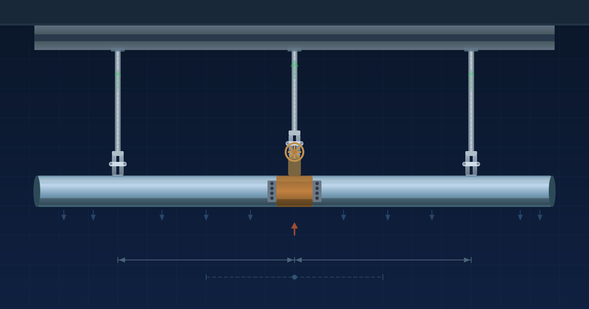
Pipe hanger load and weight per foot are not the same number, and sizing a hanger to the per-foot weight instead of the actual support load understates the hanger by a factor of the span length.
Why Weight per Foot and Hanger Load Are Different Numbers
The weight per foot and the hanger load are two numbers that look similar but measure completely different things, and confusing them is the most common hanger-sizing error: weight per foot (lb/ft) is a property of the pipe, while the hanger load (lb, a force) is what one support actually carries over its span.
Weight per foot describes how heavy the pipe is along its length. Hanger load describes the total force one support must carry. A pipe that weighs 5.1 lb/ft does not put 5.1 lb on each hanger. An interior hanger collects the weight of pipe over its full tributary length, from midspan on one side to midspan on the other.
A 2-inch steel water line weighs about 5.1 lb/ft, but a hanger on a 10-foot span does not carry 5.1 lb: it carries 5.1 × 10 = 51 lb. The per-foot weight is distributed along the pipe; each hanger gathers its whole tributary span's worth. Sizing a hanger to 5.1 lb when it carries 51 lb understates the support by a factor of the span length. The hanger and its rod are selected against the load (51 lb), not the per-foot weight — sized against that force at the support, not the linear property of the pipe.
Two questions decide support design, and this article and the Pipe Support Spacing article answer them in sequence. The Pipe Support Spacing article computed the span (how far apart supports can go, from bending stress and sag). This article computes the load (what each support carries: weight per foot times that span, plus any concentrated valve load). MSS SP-58 Table 4 sets the maximum spacing; the hanger is then selected against the resulting load. Spacing first, load second: the two halves of support design.
Calculator Inputs: Material, Size, Contents, Spacing, Insulation, Concentrated Load
The calculator covers two modes. Size mode computes the hanger load and returns the MSS SP-58 Table 4 maximum spacing. Check mode verifies a proposed spacing or a hanger's allowable capacity against the calculated load.
Unit system selects US (lb, ft, in) or Metric (N, kgf, m, mm). Hanger load is a force: newtons (N) are the primary metric unit, with kilogram-force (kgf) shown in parentheses.
Pipe material controls both the pipe weight per foot and the code maximum spacing. Steel Schedule 40 follows ASME B36.10M; Copper Type L follows ASTM B88. Nominal pipe size runs from ½ in to 12 in (copper to 6 in). Inside diameter and empty weight come from the schedule, not from the nominal label.
Contents selection sets the fluid weight component: Water full-bore (table basis, mandatory on water lines), Empty/Gas (contents zero), or Other fluid (enter specific gravity). Spacing input accepts a user value or defaults to the MSS SP-58 Table 4 maximum. Optional inputs include insulation thickness and density (mineral wool 4–8 lb/ft³ = 64–128 kg/m³, fiberglass 0.6–3 lb/ft³, calcium silicate 15 lb/ft³ = 240 kg/m³), a concentrated load at the support for valves or in-line equipment (lb or N), and additional distributed load per foot for heat tracing or jacketing.
Check mode adds a proposed hanger rated allowable capacity (the manufacturer working load, not ultimate strength) and a check basis: spacing check, capacity check, or both. The calculator returns OD and ID, empty pipe weight per foot, contents weight per foot, insulation weight per foot, total weight per foot, code maximum spacing, tributary length used, and total hanger load. Check mode reports a spacing ratio (proposed/maximum), a capacity ratio (load/allowable), and a verdict by tier.
The calculator does not account for bending stress, deflection, or sag between supports (that is the Pipe Support Spacing Calculator), end spans, unequal spans, trapeze configurations, structure or attachment design, rod tension, seismic, wind, thermal, dynamic, water-hammer, vertical riser clamps, or specific hanger product ratings.
Weight per Foot: Pipe, Water Full-Bore, Insulation, and the Inside-Diameter Rule
The weight per foot is the total distributed weight the pipe carries per unit length: the empty pipe metal, the water it holds full-bore, and any insulation. The water weight uses the inside diameter from the schedule, never the nominal size.
Weight builds up component by component:
weight_per_ft = empty_weight + contents_weight + insul_weight + additional

empty_weight  = pipe schedule weight [lb/ft, ASME B36.10M / ASTM B88]
water_weight  = (π/4 × ID_in²) × 62.4 / 144   [lb/ft, full bore, water at 62.4 lb/ft³]
fluid_weight  = water_weight × SG              [other fluid at specific gravity SG]
insul_weight  = π/4 × [(OD + 2t)² − OD²] / 144 × ρ   [lb/ft; t in inches, ρ lb/ft³]
The inside-diameter rule: water fills the bore, and the bore is the ID, not the nominal size. Nominal is a label. For 2-in Schedule 40 steel, the actual ID is 2.067 in (52.5 mm), not 2.000 in. Using nominal overstates the bore area and the water weight.
Worked example for a 2-in Schedule 40 steel water line (matching calculator Example 1):
ID = 2.067 in (52.5 mm), OD = 2.375 in (60.3 mm)

empty = 3.65 lb/ft (5.43 kg/m)  from ASME B36.10M schedule

water = (π/4 × 2.067²) × 62.4 / 144
       = (0.7854 × 4.273) × 0.4333
       = 3.356 × 0.4333
       = 1.45 lb/ft (2.16 kg/m)

weight_per_ft = 3.65 + 1.45 = 5.10 lb/ft (7.59 kg/m)
Water is approximately 28% of the total (1.45 of 5.10). MSS SP-58 Table 4 spacing values assume water-full pipe, so the water component is mandatory on water lines. An empty or gas line uses the same Table 4 spacing (spacing limits sag and stress regardless of contents), but the computed hanger load is lower because water weight drops to zero.
Insulation adds weight for steam, hot-water, and chilled-water lines. On small pipe with dense insulation (calcium silicate at 15 lb/ft³ = 240 kg/m³), insulation can be a substantial share of total weight. The calculator adds insulation weight from thickness and density together.
Per ASME B36.10M and MSS SP-58: weight per foot is pipe schedule weight plus water at full bore (computed at the schedule ID) plus insulation. The bore uses the schedule ID, never the nominal size.
Tributary Span and the Hanger Load: Weight per Foot Times Spacing
The hanger load is a force: the weight per foot times the tributary span, the length of pipe that one support carries. For a uniform interior hanger, the tributary span equals the spacing.
hanger_load = weight_per_ft × tributary_span + concentrated_load   [lb or N]

tributary_span = spacing (interior support, uniform pipe)
Worked example (2-in steel water, 10-ft spacing, no valve):
hanger_load = 5.10 lb/ft × 10 ft = 51 lb (227 N, 23.1 kgf)
Not 5.10 lb. Each interior hanger supports half the span on each side, totaling one full span's worth of pipe weight. The distributed weight along the pipe is gathered by the hanger over its tributary length. End supports carry half the tributary: a hanger at the pipe terminus of the same system carries 5.10 × 10/2 = 25.5 lb (113 N, 11.6 kgf), half the interior load.
The hanger and rod carry the force (51 lb), not the distributed weight (5.10 lb/ft). Sizing to 5.10 lb/ft understates the actual load by a factor of the span length. On a 10-foot span, that is a 10-fold understatement.
Force units: hanger load is a force. US pounds are the working unit; metric uses newtons (primary) with kilogram-force in parentheses. 51 lb × 4.4482 N/lb = 227 N; 51 lb × 0.4536 kgf/lb = 23.1 kgf.
Per MSS SP-58: hanger load equals weight per foot times tributary span plus any concentrated load. It is a force in pounds (or newtons), and hangers are selected against it, not against the per-foot weight.
MSS SP-58 Spacing: Read from Table 4, Not Calculated
The maximum hanger spacing is not calculated from the load; it is read from a table set by the standard. ANSI/MSS SP-58 Table 4 gives the maximum horizontal spacing for each pipe material and nominal size, on a water-full basis.
tributary_span = user spacing if entered, else MSS SP-58 Table 4 maximum
The spacing exists to limit sag and bending stress between supports (which the Pipe Support Spacing article computes from beam theory). MSS SP-58 Table 4 codifies those limits so a load check alone does not need to re-derive them. A load check does not address sag; the spacing table does. The Pipe Support Spacing Calculator computes the beam-theory span from first principles; this calculator reads the Table 4 result.
Representative Table 4 values (water-full basis):
2-in steel:    10 ft (3.0 m)
4-in steel:    14 ft (4.3 m)
6-in steel:    17 ft (5.2 m)
2-in copper:    8 ft (2.4 m)
4-in copper:   12 ft (3.7 m)
Table 4 values are discrete by material and size. The calculator uses them directly; no interpolation. An empty or gas line uses the same table spacing because spacing limits sag and stress regardless of whether the pipe is temporarily empty.
Per MSS SP-58 Table 4: spacing is read by material and size, not calculated, on a water-full basis. It limits sag and stress; the load follows from it.
Material Drives Spacing: Why Copper Is Supported Closer Than Steel
Material drives the spacing as much as size, because stiffness and strength differ by material. Steel spans furthest; copper closer; plastic closest.
Comparison at 2-in nominal, per MSS SP-58:
2-in steel:    10 ft (3.0 m)   E ≈ 29 Mpsi (200 GPa)
2-in copper:    8 ft (2.4 m)   E ≈ 17 Mpsi (117 GPa)
2-in plastic:   much closer, temperature-dependent (separate table)
Steel's higher modulus (E ≈ 29 Mpsi = 200 GPa) means less sag and lower bending stress at the same span. Copper (E ≈ 17 Mpsi = 117 GPa) is softer and sags more at the same span, so Table 4 sets a closer spacing. Material controls two things in the calculator simultaneously: the pipe weight per foot from its schedule (ASME B36.10M for steel, ASTM B88 for copper) and the Table 4 maximum spacing. Both differ significantly by material.
The hanger takeoff consequence is not trivial — at the same nominal size, copper requires 25% more hangers than steel on a 2-in line (every 8 ft vs every 10 ft). Over a 100-foot run that is 13 hangers for copper vs 10 for steel.
Plastic (PVC, CPVC, PEX) has much lower stiffness than metal and is subject to temperature-dependent creep; its allowable spacing drops sharply as temperature rises. Plastic spacing tables are separate and incompatible with metal tables. This calculator covers steel and copper, where spacing is well established in normal service conditions.
Per MSS SP-58: never use steel spacing values for copper pipe. Material governs both the weight per foot and the maximum spacing.
Concentrated Loads: Valves and Equipment at a Support
A valve, actuator, or in-line piece of equipment is a concentrated (point) load added directly to the hanger at that support, on top of the distributed pipe weight. Heavy components are placed at or near a support precisely for this reason.
hanger_load = distributed_load + concentrated_load
distributed_load = weight_per_ft × tributary_span
Worked example for a 2-in steel water line with a 75-lb (334 N) valve at the support (matching calculator Example 2):
distributed  = 5.10 lb/ft × 10 ft     =  51 lb  (227 N)
concentrated = 75 lb valve             =  75 lb  (334 N)
total        = 51 + 75                 = 126 lb  (560 N, 57.2 kgf)
The valve support carries 126 lb, 2.5 times the plain interior load of 51 lb. Sizing all hangers on the system to 51 lb would under-size the valve support by the full valve weight (75 lb).
Placing a valve mid-span adds a point load between hangers, introducing bending at the valve location and potential overstress of the span. Placing it at a support transfers the load directly to the hanger and avoids mid-span bending. This is standard practice in plumbing and mechanical piping.
Concentrated load sources include gate and globe valves, ball valves, actuators, strainers, flanged specialties, and in-line equipment. Each is assigned to its nearest support and added as a point load to that hanger. Additional distributed loads (heat tracing cable, insulation jacketing) are added per foot to the distributed weight before multiplying by span — a different category from point loads.
Per MSS SP-58: place hangers at heavy in-line components and size those hangers for distributed load plus concentrated load. Do not average the valve weight across multiple hangers.
Capacity Check: Allowable Working Load, Not Ultimate Strength
The capacity check compares the hanger load against the hanger's rated allowable (working) load: the load it is certified to carry in service, with its safety factor already built in. This is not the ultimate strength (the failure load, which is several times higher).
capacity_ratio = hanger_load / rated_allowable_capacity

Verdict tiers:
  ≤ 1.00     adequate
  1.00-1.15  marginally overloaded
  1.15-1.50  overloaded
  > 1.50     significantly overloaded
Allowable (working) load is the rated service load with the safety factor already incorporated — from MSS SP-58 and manufacturer tables, typically 5:1 for hanger components. Comparing to ultimate strength instead would eliminate that safety factor entirely.
Worked examples (matching calculator Example 4):
2-in steel, 10-ft spacing, hanger load = 51 lb (227 N)

Hanger rated  50 lb allowable:  51/50  = 1.02 → Marginally overloaded
Hanger rated 150 lb allowable:  51/150 = 0.34 → Adequate, ample margin
The 150-lb-rated hanger at 0.34 ratio provides comfortable margin. A 3/8-in diameter rod hanger assembly typically carries 600–800 lb allowable per manufacturer tables (Anvil/ASC Engineered Solutions, Cooper B-Line/Eaton, Erico/nVent CADDY, Grinnell): more than adequate for a 51-lb interior load. The correct selection checks the full assembly — rod, clevis, and clamp — against the allowable, not the rod alone.
Per MSS SP-58 and manufacturer allowable-load tables: compare hanger load to the rated allowable (working) load. Select a hanger assembly whose allowable capacity exceeds the computed load.
MSS SP-58 vs IPC and UPC: Why the Spacings Differ
ANSI/MSS SP-58, the International Plumbing Code (IPC), and the Uniform Plumbing Code (UPC) do not always agree on hanger spacing. MSS SP-58 can be more conservative (shorter spacing) than IPC or UPC, especially for larger pipe sizes.
MSS SP-58 grew from industrial piping practice, where higher temperatures, larger pipe sizes, dynamic loads, and more demanding service conditions are common. Its spacing values reflect that background. The building codes (IPC, UPC) are written for typical plumbing conditions and may allow longer spacing on some sizes.
The consequence: following MSS SP-58 satisfies most building codes but may require more hangers than the code strictly demands. Following a building code alone may allow longer spans that exceed what SP-58 would set.
The project specification names the governing basis. If the spec references MSS SP-58, use SP-58 spacings. If the spec references IPC or UPC, use the code table. Do not mix values from different standards on the same project. The Authority Having Jurisdiction (AHJ) adopts a specific code edition; confirm which edition applies before using any table value.
Per MSS SP-58, IPC, and UPC: standards differ on spacing, especially for larger pipe. The project spec and AHJ-adopted edition govern. Use the basis named in the contract documents.
Size Mode Worked Example: 2-Inch Steel Water Line at 51 Pounds
Scenario: horizontal 2-in Schedule 40 steel pipe, water-full, uninsulated, building water or process distribution. This matches calculator Example 1.
Step 1. Empty pipe weight from ASME B36.10M schedule:
empty = 3.65 lb/ft (5.43 kg/m)
Step 2. Water weight full-bore at the schedule ID (2.067 in = 52.5 mm):
water = (π/4 × 2.067²) × 62.4 / 144
       = (0.7854 × 4.273) × 0.4333
       = 3.356 × 0.4333
       = 1.45 lb/ft (2.16 kg/m)
Step 3. Total weight per foot:
weight_per_ft = 3.65 + 1.45 = 5.10 lb/ft (7.59 kg/m)
Step 4. Code maximum spacing from MSS SP-58 Table 4:
2-in steel = 10 ft (3.0 m)
Step 5. Hanger load (interior support, full tributary span):
hanger_load = 5.10 × 10 = 51 lb (227 N, 23.1 kgf)
Step 6. What the number means: each interior hanger carries 51 lb. Select hanger, rod, and clamp assembly for at least 51 lb allowable working load. Not 5.10 lb/ft.
Step 7. End support (half tributary):
end support = 5.10 × 10/2 = 25.5 lb (113 N, 11.6 kgf)
Step 8. Hanger selection: a 3/8-in rod hanger assembly rated at 600–800 lb allowable per Anvil, Cooper B-Line, or Grinnell manufacturer tables easily handles 51 lb. Confirm allowable for the full assembly (rod, clevis, clamp), not rod diameter alone.
Step 9. Insulated variant. Adding 2-in thick mineral wool insulation at 8 lb/ft³ (128 kg/m³):
OD = 2.375 in (60.3 mm); insulation thickness t = 2 in (50.8 mm)
OD + 2t = 2.375 + 4 = 6.375 in (161.9 mm)

insul = π/4 × [(6.375)² − (2.375)²] / 144 × 8
       = 0.7854 × [40.641 − 5.641] / 144 × 8
       = 0.7854 × 35.00 / 144 × 8
       = 0.7854 × 0.2431 × 8
       = 1.53 lb/ft (2.28 kg/m)

weight_per_ft = 5.10 + 1.53 = 6.63 lb/ft (9.87 kg/m)
hanger_load   = 6.63 × 10  = 66.3 lb (295 N, 30.1 kgf)
Insulation raises the hanger load 30% (51 lb to 66 lb). Select hangers for 66 lb allowable on insulated runs; do not use the bare-pipe load for insulated service.
Step 10. Summary:
Bare:       5.10 lb/ft × 10 ft = 51 lb per interior hanger, 10-ft MSS SP-58 spacing
Insulated:  6.63 lb/ft × 10 ft = 66 lb per interior hanger

Weight per foot (5.10 lb/ft) is NOT the hanger load (51 lb).
Select the hanger against the force, not the per-foot property.
Cross-reference Pipe Support Spacing Calculator: the 10-ft spacing derives from beam-theory stress and deflection limits; this example takes that spacing as given and computes the resulting load.
Check Mode Worked Examples: Over-Spacing and Capacity at the Limit
Two check scenarios correspond to calculator Examples 3 and 4.
Check 1: Spacing over the MSS SP-58 limit (calculator Example 3)
Scenario: same 2-in steel water line, proposed support every 14 ft (4.3 m). Code maximum from Table 4 is 10 ft (3.0 m).
Step 1. Spacing ratio:
spacing_ratio = 14 ft / 10 ft = 1.40 → Over-spaced (1.15-1.50 tier)
Step 2. Load at the over-spacing:
hanger_load = 5.10 × 14 = 71.4 lb (317 N) vs 51 lb at code spacing
Step 3. Verdict: the 14-ft spacing is 1.40 times the 10-ft MSS SP-58 maximum. Too few hangers, risking sag between supports, higher bending stress, and potential joint failure at threaded or mechanical couplings. Add hangers to reduce the span to 10 ft.
Check 2: Capacity at the limit (calculator Example 4)
Scenario: same 2-in steel, 10-ft spacing, 51-lb load. Proposed hanger rated 50 lb allowable.
Step 4. Capacity ratio:
capacity_ratio = 51 lb / 50 lb = 1.02 → Marginally overloaded (1.00-1.15 tier)
Step 5. Fix: a hanger rated 150 lb allowable gives 51/150 = 0.34, ample margin. Select the higher-rated assembly.
Verdict tier summary:
| Ratio | Spacing check | Capacity check |
|---|---|---|
| ≤ 1.00 | Adequate | Adequate |
| 1.00–1.15 | Marginally over-spaced | Marginally overloaded |
| 1.15–1.50 | Over-spaced | Overloaded |
| > 1.50 | Significantly over-spaced | Significantly overloaded |
A layout must pass both checks. Spacing (sag and stress) and capacity (hanger strength) are independent criteria: over-spacing risks pipe sag while the hanger still has reserve, and an overloaded hanger can fail even at proper spacing.
Per MSS SP-58 and manufacturer tables: spacing ratio is proposed/maximum; capacity ratio is load/allowable. Both must be at or below 1.00 for a passing result.
Application Boundaries: End Spans, Trapeze, Seismic, Rod and Structure Design
The calculator applies to interior single-pipe gravity load on a horizontal uniform run.
End spans and unequal spans: an interior support carries one full tributary span (half each side). End supports and unequal spans change the tributary load distribution and require separate treatment.
Trapeze and multi-pipe assemblies: a trapeze carrying several pipes across a horizontal beam distributes total load across the beam and its connections; the calculator sizes single-pipe interior hangers only.
Bending stress and deflection: the calculator does not evaluate pipe bending stress, deflection, or sag between supports. MSS SP-58 Table 4 spacing accounts for those limits. For beam-theory span from stress and deflection first principles, use the Pipe Support Spacing Calculator. A load check alone is not sufficient to verify span; the spacing table must also be satisfied.
Structure and attachment design: building structure, concrete inserts, embedded plates, beam clamps, and anchor design are separate from hanger load screening. Rod tension, bending, corrosion allowance, and temperature derating of rod capacity are not computed here.
Seismic, wind, and dynamic loads: gravity only. Seismic bracing (lateral and longitudinal), wind, water-hammer, vibration, and other dynamic loads require separate design per applicable code (ASCE 7, NFPA 13). Cross-reference Seismic Bracing for Pipes.
Thermal: thermal expansion guides and anchors are separate from gravity hangers. A clevis hanger allows axial movement; guides and anchors restrain it. Cross-reference Pipe Expansion Loop Sizing.
Vertical risers: riser clamps carry load axially at floor penetrations and are designed differently from horizontal hangers. Not covered here.
Plastic and other materials: PVC, CPVC, PEX, cast iron, and stainless steel use different schedule tables and spacing tables; plastic spacing is temperature-dependent. This calculator covers Steel Schedule 40 (ASME B36.10M) and Copper Type L (ASTM B88).
Per MSS SP-58 and manufacturer guidelines: interior single-pipe gravity screening is the calculator scope. End spans, trapeze, bending/deflection (see Pipe Support Spacing), structure, seismic, thermal, risers, plastic pipe, and specific product selection require separate qualified analysis and approval by the engineer of record.
Pipe Hanger Load Calculator
Pipe hanger load per MSS SP-58: computes the weight per foot (empty pipe from schedule, water full-bore at the schedule ID, insulation from thickness and density) and multiplies by the tributary span to give the force one support carries, plus any concentrated valve load. Size mode returns weight per foot, MSS SP-58 Table 4 maximum spacing, and the hanger load; Check mode verifies a proposed spacing or a hanger's allowable capacity with pass/fail ratios and tier verdicts. Covers Steel Schedule 40 (ASME B36.10M) and Copper Type L (ASTM B88), reporting force in pounds or newtons.
Open Pipe Hanger Load CalculatorFAQ
How do I calculate the load on a pipe hanger?
Per MSS SP-58: multiply weight per foot by the tributary span and add any concentrated load at the support. A 2-in steel water line at 5.1 lb/ft (7.6 kg/m) on a 10-ft (3.0-m) span carries 51 lb (227 N) per interior hanger. Select the hanger for 51 lb, not for 5.1 lb/ft.
What is the difference between weight per foot and hanger load?
Per MSS SP-58: weight per foot (lb/ft or kg/m) is a property of the pipe describing how heavy it is along its length. Hanger load (lb or N) is a force — what one support actually carries over its tributary span. For a 2-in steel water line: 5.1 lb/ft × 10 ft = 51 lb. Sizing a hanger to the per-foot weight understates it by a factor equal to the span length.
How far apart should pipe hangers be?
Per MSS SP-58 Table 4: spacing is read by material and nominal size from a table, not calculated from the load. On a water-full basis: 2-in steel 10 ft (3.0 m), 2-in copper 8 ft (2.4 m), with spacing increasing for larger sizes. Plastic pipe is supported closer and uses temperature-dependent separate tables.
Does the water in the pipe count toward the load?
Per MSS SP-58: yes. Table 4 spacing values use a water-full basis, and the hanger load must include water weight. For 2-in Schedule 40 steel: pipe metal 3.65 lb/ft (5.43 kg/m) plus water 1.45 lb/ft (2.16 kg/m) equals 5.10 lb/ft (7.59 kg/m) total. Water is about 28% of total weight on this size. An empty or gas line drops the water component; the spacing table value remains the same.
Why use inside diameter for water weight, not nominal size?
Per ASME B36.10M: water fills the bore, and the bore is the schedule inside diameter (ID), not the nominal size label. For 2-in Schedule 40 steel, ID is 2.067 in (52.5 mm), not 2.000 in. Using nominal size overstates the bore area and therefore the water weight.
What capacity should I check a hanger against?
Per MSS SP-58 and manufacturer allowable-load tables: check against the rated allowable (working) load, which already includes the safety factor (typically 5:1 for hanger components per Anvil/ASC Engineered Solutions, Cooper B-Line/Eaton, Erico/nVent CADDY, Grinnell). Do not check against ultimate strength; ultimate is the failure load and does not include the required service margin.
How is this different from pipe support spacing?
Per MSS SP-58 and beam theory: pipe support spacing determines how far apart supports can go, limited by bending stress and midspan sag (the Pipe Support Spacing Calculator). Hanger load determines what each support carries: weight per foot times the span. Spacing first, load second — the two are sequential steps in support design, not alternatives.
Related Calculators
- Pipe Support Spacing Calculator: Maximum span from bending stress and deflection; this hanger load calculator carries the reaction over the span that one determines (article).
- Pipe Slope Calculator: Gravity drainage slope per IPC 704 and Manning's equation; sag between hangers can reverse slope on drained lines (article).
- Pipe Expansion Loop Sizing Calculator: Thermal expansion loops; hangers allow axial movement while guides and anchors restrain it.
- Compressed Air Pipe Sizing Calculator: Darcy-Weisbach air main sizing; air mains need hangers sized for pipe plus content weight (article).
- Hazen-Williams Pipe Flow Calculator: Pressurized water pipe flow per AWWA M22 (article).
- Expansion Tank Sizing Calculator: Thermal expansion control per IPC Section 607.3 (article).
- Fire Pump Performance Curve Calculator: NFPA 20 curve acceptance (article).
Standards References
- ANSI/MSS SP-58 — Pipe Hangers and Supports: Materials, Design, Manufacture, Selection, Application and Installation, Manufacturers Standardization Society. Table 4: maximum hanger spacing by material and nominal size, water-full basis.
- IPC — International Plumbing Code, Chapter 3: pipe support provisions and spacing requirements.
- UPC — Uniform Plumbing Code, Table 313.3: hanger spacing by material.
- ASME B36.10M — Welded and Seamless Wrought Steel Pipe: OD, wall thickness, ID, and weight per foot for Schedule 40 steel pipe.
- ASTM B88 — Standard Specification for Seamless Copper Water Tube: OD, wall, ID, and weight for Type K, L, and M copper tube.
- ASME B31.1 — Power Piping: pipe support requirements for power plants.
- ASME B31.3 — Process Piping: pipe support requirements for process piping.
- Anvil (ASC Engineered Solutions) — Pipe Hanger and Support Catalog: allowable (working) load tables for rod, clevis, ring, and beam-clamp assemblies.
- Cooper B-Line (Eaton) — B-Line Series Pipe Hangers and Support Catalog: rod and hanger allowable loads by assembly type.
- Erico/nVent CADDY — CADDY Pipe Support Catalog: allowable working loads by rod diameter and hanger type.
- Grinnell (ASC Engineered Solutions) — Grinnell Pipe Hanger Products Catalog: allowable loads for hanger assemblies.