Sewage Ejector Pump Sizing Calculator — Table 712.4.2, the 2 ft/s Floor, and the Solids Passage
On this page
Calculate
This selector governs every field, label, result and export on this page, and it takes priority over the site header switch. Switching converts the values you entered rather than reinterpreting them, so 50 gpm becomes 189.3 L/min and returns to exactly 50 gpm when you switch back. Nominal pipe sizes stay in inches in both systems with millimetres alongside, because that is how discharge pipe is specified and ordered.
What Enters the Pit
This is the first question because it decides the solids passage, the device class and whether this is the right page. Water closets set the passage at 2 inches, which is 51 mm; sanitary fixtures without one set it at 1/2 inch, which is 13 mm, in the 2024 code. Clear water and storm sumps have no solids passage requirement, no Table 712.4.2 minimum and no velocity floor, and are sent to the Sump Pump Capacity page rather than answered here.
The Discharge Pipe
The line leaving the pump, not the gravity drain feeding the pit and not the drain that receives the discharge downstream. Nominal sizes are trade designations rather than measurements of anything on the pipe, which is why the bore is asked for separately below. Table 712.4.2 lists 2, 2-1/2 and 3 inch only; on the other three sizes no capacity is invented and the 2 feet per second floor is applied to the actual bore instead.
The solids passage and the velocity are both decided by the actual bore, not the nominal size. A 2 inch Schedule 80 pipe has a smaller bore than a 2 inch Schedule 40 pipe and will not pass 2 inch solids. Schedule 40 is applied as the default and the result says so. For cast iron, no hub, HDPE or any other material, choose the custom option and enter the actual inside diameter rather than accepting a schedule figure that does not describe the pipe.
The vertical rise from the pump discharge to the point where the line enters the gravity system. It does not change with flow, which is what separates it from friction. It is required because the total dynamic head has no floor without it.
The Pump, the Head and the Installation (none of these block Calculate)
Use the flow from the pump curve at the total dynamic head this page calculates, not the maximum flow printed on the box, which is quoted at or near zero head, and not a fixture unit total. Drainage fixture units size drain pipe and are not a pump capacity. Leave it blank to get the requirements without a verdict on a pump.
A candidate entered at its free flow rating will pass a velocity check it would fail in the installed condition, so the page asks where the number came from and says so where the basis is a headline rating. The result carries this as a confidence badge on the flow.
Left undecided, the page reports the requirements and names the device class that meets them rather than withholding the result. The choice matters for one check: an ejector passes solids whole and its bore must be at least as large as the solids, while a grinder and a macerating assembly break them down and are measured against a minimum discharge opening instead.
The head consumed by the pipe and its fittings, which rises roughly with the square of the flow. Working it out from the run length, the fittings and the material is a separate calculation. Without it the total dynamic head is reported as a floor rather than as the duty point.
Applies where the line enters a pressurised system rather than an open gravity drain. It converts to head by dividing by 0.433 psi per foot, so 5 psi is 11.55 feet. Multiplying instead returns 2.17 feet, which is wrong by more than five times and looks entirely reasonable in a column of figures. Leave blank for a discharge into gravity drainage.
Section 712.3.2 sets not less than 18 inches, which is 457 mm, unless otherwise approved. Left blank the check is reported as not evaluated rather than passed.
Section 712.3.2 sets not less than 24 inches, which is 610 mm, unless otherwise approved. Chicago requires 30 inches, which is 762 mm. Note that the depth is not usable depth: the level control has to keep the effluent clear of the inlet invert before the drawdown volume is even considered.
Measured down from the rim to the invert, meaning the bottom of the gravity drain where it enters the sump. Entered together with the maximum effluent level it turns the Section 712.3.4 level control requirement from a note into a check.
The highest level the control lets the effluent reach, measured down from the same rim as the invert above. A larger number means a lower level. Section 712.3.4 requires the effluent to be kept at least 2 inches, which is 51 mm, below the inlet invert at all times.
Section 712.3.5 allows the discharge to connect to a building drain, soil stack, waste stack or horizontal branch drain. Two extra rules attach only to a connection into horizontal drainage piping: the wye into the top, and the ten diameter clearance from a stack base.
Published guidance citing SSPMA Standard 101 warns that a grinder pump ahead of a septic system causes complete failure of the septic system, because grinding destroys the particle structure anaerobic digestion depends on. Answering this turns that from general advice into a check.
Overview
On a sewage force main the usual instinct about pipe size runs backwards. Every other pipe on a job is sized with the same reflex, that a larger diameter means less friction and more headroom. Here a larger discharge pipe lowers the velocity, and below 2 feet per second the solids stop moving and settle out along the pipe. The line chosen to be generous is the line that blocks.
Table 712.4.2 is that velocity floor written as a capacity. It gives 21 gallons per minute on a 2 inch discharge, 30 on 2-1/2 inch and 46 on 3 inch, and those figures match the flow needed to hold about 2 feet per second in Schedule 40 pipe, within rounding. The two rules never contradict each other because they are the same requirement from opposite ends.
Two inputs decide almost everything else. Whether water closets discharge into the pit sets the solids passage at 2 inches rather than 1/2 inch, and that in turn sets the minimum bore of the discharge pipe. And the bore is the actual inside diameter rather than the nominal size, which matters more than it sounds: a 2 inch Schedule 40 pipe has a 2.067 inch bore and passes 2 inch solids, while a 2 inch Schedule 80 pipe has a 1.939 inch bore and does not.
One thing this calculator will not do is turn a drainage fixture unit total into a pump flow. Fixture units size drain pipe. The relationship that does exist in this part of the code runs the other way: the pump discharge places a fixture unit load on the gravity drain downstream, at two fixture units per gallon per minute.
What to Look at First
Read the waste type before anything else. It decides the solids passage, the device class and whether this is even the right page. A clear water or storm sump has no solids passage requirement, no Table 712.4.2 minimum and no 2 feet per second floor, and those cases are routed to the sump pump page rather than answered here.
Then read the bore, not the nominal size. Two calculations depend on the inside diameter and neither can use the label. A 2 inch Schedule 40 pipe bores 2.067 inches and passes 2 inch solids; a 2 inch Schedule 80 pipe bores 1.939 inches and does not. Velocity depends on the square of the same figure.
Then read the velocity line, and read its direction. Where the velocity falls below 2 feet per second the pipe is too large for the flow rather than the flow too small for the pipe, so the useful move is usually a smaller discharge rather than a larger pump. That is the opposite of what every other pipe on the job rewards.
How to Use This Calculator
Say what enters the pit. Water closet discharge, sanitary fixtures without a water closet, clear water only, or storm water and groundwater. The last two are a different device under different rules and the calculator will send you to the sump pump page rather than answer them here.
Enter the discharge pipe nominal size and its bore basis. The default is Schedule 40. Change it where the force main is Schedule 80, or enter a custom inside diameter for cast iron, HDPE or anything else, because the solids passage and the velocity are both decided by the actual bore.
Enter the static lift, meaning the vertical rise from the pump discharge to the point of connection. Add the friction loss through the discharge piping and fittings if you have it. Without friction the calculator reports the static lift as a floor and says the head is incomplete.
Enter a candidate pump flow if you are checking a specific pump, and say where the figure came from. Use the flow from the pump curve at the calculated head, not the headline number on the box, which is usually quoted at or near zero head.
Leave the flow blank if you are working out the requirement rather than checking a pump. The calculator still returns the solids passage, the Table 712.4.2 minimum, the minimum flow to hold the velocity floor and the head.
Add the pit dimensions, the inlet invert depth, the connection details and the septic answer to get the installation checks. Anything left blank is reported as not evaluated rather than passed.
Only what enters the pit, the discharge pipe size and the static lift are required. The candidate flow, the friction, the discharge pressure, the pit dimensions, the level control figures, the connection answers and the septic answer are all optional and none of them block Calculate; each one left blank is reported as not evaluated, which is not the same as compliant.
Inputs & Outputs
Inputs
Outputs
Sewage Ejector Sizing Formula
The arithmetic is short. What matters is which diameter goes into it.
Velocity in the discharge pipe
velocity_fps = 0.4085 * gpm / bore_in ^ 2
The bore is the actual inside diameter for the material and schedule, not the nominal size. Velocity falls with the square of it.
Flow needed to hold the floor
min_gpm = 2 * bore_in ^ 2 / 0.4085
The flow at which the pipe reaches 2 feet per second, which is 0.61 metres per second.
Table 712.4.2 minimum capacity
2 in gives 21 gpm, 2-1/2 in gives 30 gpm
3 in gives 46 gpm
Those are the only three sizes the table lists. Any other discharge size is checked against the velocity floor directly.
Pressure to head
head_ft = psi / 0.433
Five psi is 11.55 feet of head. The reverse multiplies: 20 feet of head is 8.66 psi.
Total dynamic head
tdh_ft = static_lift + friction + discharge_head
Static lift does not change with flow and friction does, so the two are summed at the design flow rather than compared.
Load on the gravity drain downstream
dfu_load = 2 * gpm
The drainage fixture unit load the pump discharge places on the gravity piping it enters.
Unit conversions
1 gallon per minute equals 3.785411784 litres per minute, 1 foot equals 0.3048 m and 1 inch equals 25.4 mm.
The remaining rules are conditions rather than equations: the solids passage requirements, the bore against the solids passage, the pit dimensions, the level control clearance, the discharge connection rules and the valve requirement.
Sewage Ejector vs Grinder Pump vs Macerating Toilet
Four devices appear in the same catalogue and only one of them is a sewage ejector. The difference between them is how far the solids are broken down before they enter the pipe, and the discharge opening shrinks as that increases.
A clear water sump pump moves water without solids. It has no solids passage rating and no standing in this part of the code at all. It is the device for a groundwater or storm sump, and published guidance describes one installed in a sewage application as compromised by solid waste in under about eighteen months. That is long enough for the substitution to be forgotten before the pump fails, which is what makes it a common mistake rather than an obvious one.
A sewage ejector passes solids whole. Where water closets discharge into the pit it must handle 2 inch spherical solids, and the discharge pipe bore must be at least as large, because a pump that lifts a 2 inch solid into a smaller pipe simply blocks at the pipe. This is the standard device for a below grade bathroom group discharging to a gravity sewer.
A grinder pump macerates solids into a slurry before discharging them. That is what lets it use a small bore line: where it receives water closets the code sets the discharge opening at not less than 1-1/4 inches. A grinder is the device for a long run, a high lift or a low pressure force main, where an ejector would need a pipe too large to hold velocity.
A macerating toilet assembly serving a single water closet needs a discharge opening of not less than 3/4 inch. It is the smallest of the four and the most limited in what it can serve.
| Device | Solids treatment | Minimum discharge | Metric |
|---|---|---|---|
| Clear water sump pump | None, no rating | Not rated under Section 712 | not applicable |
| Sewage ejector | Passes solids whole | Bore not less than the solids passed | 51 mm at a water closet |
| Grinder pump | Macerates to a slurry | 1-1/4 in opening at a water closet | 32 mm |
| Macerating toilet assembly | Macerates, single closet | 3/4 in opening | 19 mm |
One consequence is worth stating on its own because the failure is total rather than gradual. Published guidance citing SSPMA Standard 101 warns that a grinder pump must not be installed ahead of a septic system, because grinding destroys the particle structure that anaerobic digestion depends on and causes complete failure of the septic system. Where the site drains to a septic tank, a solids handling ejector is the device and a grinder is not.
Solids Passage Requirement
The first question on a sewage pump is not how much it moves but what it can move, and the answer comes from one fact about the pit.
Where the pump or ejector receives the discharge of water closets, it shall be capable of handling spherical solids with a diameter of up to and including 2 inches, which is 51 mm. That is the case for any below grade bathroom group, and it is the figure most residential ejectors are built to.
Where it does not receive water closet discharge, the requirement is smaller. In the 2024 code that figure is 1/2 inch, which is 13 mm. It is worth knowing that this moved between editions: the 2012 code gave 1 inch, and the change came in the 2018 edition. An older textbook, an older submittal or a jurisdiction still working from the earlier code may show 1 inch, and that is not an error for its own edition. Chicago retains 1 inch, which is the same figure carried forward rather than a local invention.
The requirement does not stop at the pump. The inside diameter of the discharge piping shall be not less than the solid passing capacity of the pump it serves, so choosing a pump that passes 2 inch solids commits the discharge line to a bore of at least 2 inches. That comparison is between two diameters and it has to be made against the actual bore rather than the nominal size, which is covered in its own section below.
Two devices sit outside this rule because they do not pass solids whole. A grinder pump macerates, so its constraint is a minimum discharge opening of 1-1/4 inches rather than a solids passage. A macerating toilet assembly is the same idea at 3/4 inch. Applying the solids passage test to either of them produces a failure the code does not intend.
Table 712.4.2 Minimum Pump Capacity
The code sets a minimum capacity for a sewage pump based on the diameter of the discharge pipe, and the table that carries it is three rows long.
A 2 inch discharge pipe requires not less than 21 gallons per minute, which is 79.5 litres per minute. A 2-1/2 inch pipe requires 30 gallons per minute, or 113.6 litres per minute. A 3 inch pipe requires 46 gallons per minute, or 174.1 litres per minute.
| Discharge pipe | Table 712.4.2 minimum | Metric | Schedule 40 bore | Flow to hold 2 ft/s |
|---|---|---|---|---|
| 1-1/4 in | no row | not listed | 1.380 in | 9.3 gpm |
| 1-1/2 in | no row | not listed | 1.610 in | 12.7 gpm |
| 2 in | 21 gpm | 79.5 L/min | 2.067 in | 20.9 gpm |
| 2-1/2 in | 30 gpm | 113.6 L/min | 2.469 in | 29.8 gpm |
| 3 in | 46 gpm | 174.1 L/min | 3.068 in | 46.1 gpm |
| 4 in | no row | not listed | 4.026 in | 79.4 gpm |
Read on its own that looks like an arbitrary list, and the natural question is why a larger pipe should demand a larger pump rather than a smaller one. The answer is that the table is not about capacity at all. It is the 2 feet per second velocity floor expressed as a flow.
Work out the flow needed to hold 2 feet per second in each bore, using Schedule 40 inside diameters, and the figures come to 20.9 gallons per minute in a 2 inch pipe, 29.8 in a 2-1/2 inch pipe and 46.1 in a 3 inch pipe. Every row matches within rounding.
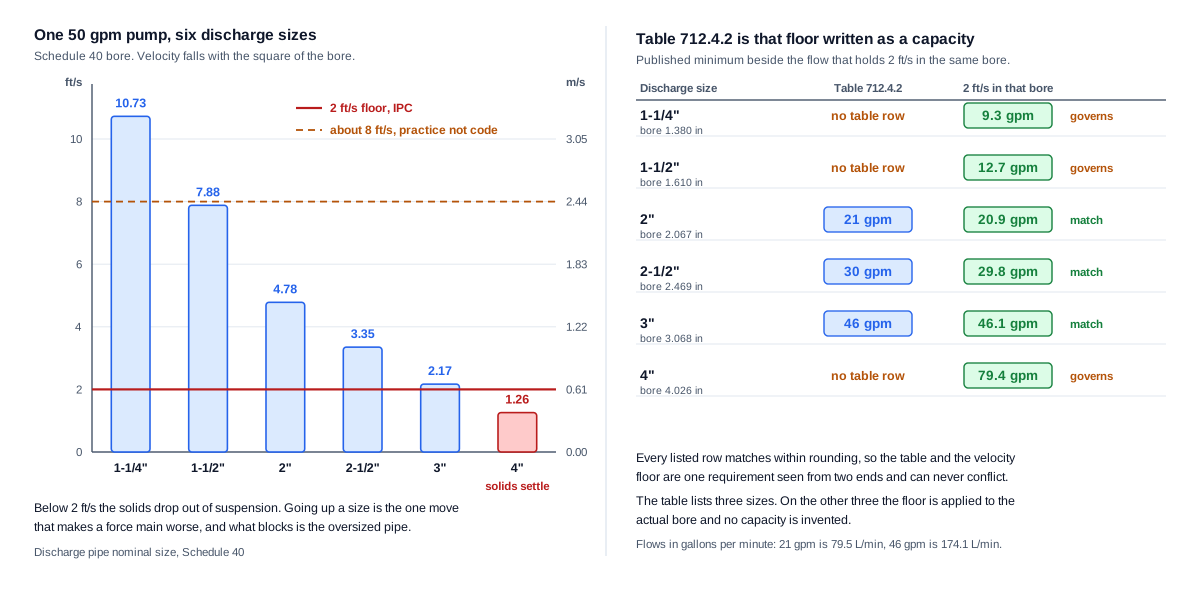
That has two practical consequences. The first is that the table and the velocity requirement can never conflict, so satisfying one satisfies the other on the sizes the table lists. The second is that the table stops at 3 inch, and a 1-1/4, 1-1/2 or 4 inch discharge has no row to read. This calculator does not invent one. It applies the velocity floor to the actual bore and reports the minimum flow directly, which gives about 9.3 gallons per minute at 1-1/4 inch, 12.7 at 1-1/2 inch and 79.4 at 4 inch.
The code does not state that the table was produced by solving the velocity requirement for flow, and this page does not claim it was. What is verifiable is that the two agree on every listed row, and that published guidance on the table says the tabulated values assure the velocity stays above 2 feet per second.
Why a Bigger Discharge Pipe Can Be Worse
This is the one place on a plumbing job where going up a pipe size makes the installation worse rather than safer, and the reason is that a force main carries solids in suspension rather than water alone.
Velocity is what holds them there. The code requires discharge piping to be sized for a flow velocity of not less than 2 feet per second, and below that the solids drop out of suspension and settle along the bottom of the pipe. They do not clear on the next cycle, because the next cycle runs at the same velocity.
Velocity falls with the square of the bore, so the effect of going up a size is sharper than it feels. Take a pump delivering 50 gallons per minute into Schedule 40 pipe. In a 2 inch discharge it runs at 4.78 feet per second. In 2-1/2 inch, 3.35. In 3 inch, 2.17, still above the floor but with little left. In 4 inch it drops to 1.26 feet per second, well below, and the pipe begins to fill from the bottom.
What fails in that installation is not the pump and not the fittings. It is the length of oversized pipe someone specified to be generous, and the symptom arrives slowly enough that the pipe size is rarely suspected.
The remedy runs the same way. Where the velocity is below the floor, the useful move is usually a smaller discharge pipe rather than a larger pump, and this calculator reports both the minimum flow that would hold the floor in the current bore and the smaller size that works at the flow already available.
The floor is a floor and not a target, which is the other half of the same point. Force main practice keeps velocity roughly between 2 and 8 feet per second, because friction rises with the square of velocity and takes head, noise and wear with it. A high velocity is worth reviewing, and it is a practice figure rather than a code limit, so this page reports it as an advisory and says so.
Nominal Pipe Size Versus Actual Bore
Two calculations on this page depend on the inside diameter of the discharge pipe, and neither of them can use the nominal size.
The first is the solids comparison. The code requires the inside diameter of the discharge piping to be not less than the solid passing capacity of the pump, which is a comparison between two diameters in inches.
Take a sewage ejector serving water closets, so the required solids passage is 2 inches, discharging into a 2 inch nominal pipe.
In Schedule 40 the bore is about 2.067 inches, which is 52.5 mm. That is larger than the 2 inch solid the pump must pass, so the pipe accepts it.
In Schedule 80 the bore is about 1.939 inches, which is 49.3 mm. That is smaller than 2 inches, so a solid the pump is required to pass cannot leave through the pipe.
Identical on the drawing, opposite on site. A calculator comparing a solids requirement against the label passes both, and the failure only appears when the line blocks.
| Nominal size | Schedule 40 bore | Metric | Schedule 80 bore | Metric |
|---|---|---|---|---|
| 1-1/4 in | 1.380 in | 35.1 mm | 1.278 in | 32.5 mm |
| 1-1/2 in | 1.610 in | 40.9 mm | 1.500 in | 38.1 mm |
| 2 in | 2.067 in | 52.5 mm | 1.939 in | 49.3 mm |
| 2-1/2 in | 2.469 in | 62.7 mm | 2.323 in | 59.0 mm |
| 3 in | 3.068 in | 77.9 mm | 2.900 in | 73.7 mm |
| 4 in | 4.026 in | 102.3 mm | 3.826 in | 97.2 mm |
The second calculation is the velocity, which depends on the square of the bore. Using a nominal size there is wrong on every pipe and wrong optimistically on heavier wall material, because a heavier wall means a smaller bore and a higher real velocity than the nominal figure suggests. That direction happens to be safe against settling and unsafe against friction and wear, so it is not a conservative error either way.
This calculator therefore asks for the bore basis rather than assuming one. Schedule 40 is the default because it is the common case, and the result names the basis it used, so a figure produced on the default is visibly a figure produced on the default. Where the force main is another material, a custom inside diameter can be entered directly.
Total Dynamic Head for Sewage Ejectors
A pump has to lift the effluent and push it through the pipe, and the head it must develop is the sum of three things rather than the height on the drawing.
Static lift is the vertical rise from the pump discharge to the point where it enters the gravity system. It does not change with flow. A pump lifting 12 feet lifts 12 feet whether it is moving 20 gallons per minute or 60.
Friction loss is the head consumed by the discharge pipe and its fittings, and it does change with flow, rising roughly with the square of it. A long run, a small bore, several elbows and a check valve all add to it.
Discharge pressure is any pressure required at the point of connection, which applies where the line enters a pressurised system rather than an open gravity drain. Where it is given in psi it converts to feet of head by dividing by 0.433, so 5 psi is 11.55 feet. The reverse multiplies, so 20 feet of head is 8.66 psi. That division is worth care: multiplying instead returns 2.17 feet for 5 psi, which is wrong by more than five times and looks entirely reasonable in a column of figures.
The three are summed at the design flow, which is the point most often missed. A static lift of 12 feet with 8 feet of friction is a total dynamic head of 20 feet, and the pump curve has to be read at 20 feet rather than at 12.
Where the friction is unknown this calculator reports the static lift and states that the head is incomplete, rather than presenting a floor as though it were the duty point. A pump chosen against the static lift alone will deliver less flow than expected once the pipe is connected, and less flow means lower velocity, which is where the settling problem starts.
Sewage Ejector Pit and Discharge Connection Rules
A correctly sized pump in a non compliant pit is not a compliant installation, and none of these rules appear anywhere in the capacity arithmetic.
The pit shall be not less than 18 inches in diameter, which is 457 mm, and not less than 24 inches in depth, which is 610 mm, unless otherwise approved. Chicago requires 30 inches of depth, which is 762 mm. The pit shall be accessible and located so that all drainage flows into it by gravity, and the bottom shall be solid and give permanent support to the pump.
The cover is part of the requirement rather than an accessory. It shall be gastight, removable, installed not more than 2 inches below grade or floor level, and adequate to support the loads in the area of use. The pit shall be vented in accordance with the vent chapter, like any other part of the drainage system, and this calculator does not size that vent.
The level control is where the usable depth disappears. The effluent shall at all times be prevented from rising to within 2 inches of the invert of the gravity drain inlet into the sump. That is a control setting rather than a dimension, and it means the 24 inch minimum depth is not 24 inches of working volume. What is left between the on and off levels is the drawdown, which decides how often the pump starts and how long the motor lasts, and the code does not set it.
The discharge connection has two rules and both matter. Where the discharge line connects into horizontal drainage piping, the connection shall be made through a wye fitting into the top of the piping, because a pumped discharge entering the side or bottom of a flowing drain backs up into it. And that wye shall be located not less than 10 pipe diameters from the base of any soil stack, waste stack or fixture drain, because the base of a stack is the most hydraulically disturbed point in the system.
Those ten diameters are diameters of the receiving pipe rather than of the discharge, which is easy to get backwards. A 4 inch receiving drain needs 40 inches of clearance whatever size the discharge line is.
Finally, a check valve and, after it, a gate valve are required in the discharge piping between the pump and the gravity system, with access to both. Chicago allows a check valve alone in single family residential buildings.
Drainage Fixture Units Are Not Pump Flow
Almost everyone arriving at this page has just sized a gravity drain, and the number in front of them is a drainage fixture unit total. It is not a flow rate and there is no conversion from one to the other.
Drainage fixture unit values exist to size drainage pipe. They are a probability weighting rather than a measurement, and published guidance on sizing sewage lift stations says plainly that those values should be used for calculating drainage pipe size and not for the flow capacity needed for a sewage or ejector pump.
There is a fixture unit relationship in this part of the code, and it points the other way. The drainage load a sewage pumping unit places on the gravity piping downstream is two drainage fixture units for every gallon per minute of pump discharge. So a pump delivering 50 gallons per minute adds a 100 fixture unit load to the drain it enters.
Read those two sentences together and the direction is clear. The pump flow produces a fixture unit load. The fixture unit load does not produce a pump flow.
Where the design flow should come from is the anticipated discharge, and a fixture count is a poor proxy for it because it misses the items that dominate. Published guidance names body showers and cooling tower drainage as examples, and equipment drains, laundry and process flows behave the same way: they are single fixtures with flow rates far above their fixture unit weighting.
The second half of the same problem is the pump rating. A headline flow on a box is usually quoted at or near zero head, and the flow that matters is what the pump delivers at the total dynamic head the installation presents. A figure taken from either the fixture unit total or the box can pass a velocity check on paper and fail it in the ground.
What Is a Sewage Ejector Pump
A sewage ejector is the pump that moves sanitary waste uphill when gravity is not available. A basement bathroom below the sewer line, a fixture group in a converted cellar, a lift station at the low point of a site: in each case the waste collects in a sealed pit and a pump lifts it into the gravity system above.
What separates it from an ordinary pump is that it has to move solids without breaking them down. The impeller and the passage through the pump are built to pass a spherical solid whole, at 2 inches where water closets discharge into the pit. That requirement then travels into the pipework, because a pump that passes 2 inch solids into a pipe with a smaller bore simply blocks at the pipe instead.
The second thing that separates it is the discharge itself. A gravity drain runs part full and uses slope to move waste. A force main runs full and uses velocity, and that velocity has to stay high enough to keep the solids in suspension for the whole length of the run. The code sets that floor at 2 feet per second, and it is the reason a force main is sized in the opposite direction from every other pipe on the job.
The pit matters as much as the pump. It has to be at least 18 inches in diameter and 24 inches deep, sealed with a gastight cover, vented under the vent chapter, and arranged so the effluent never rises to within 2 inches of the invert of the pipe feeding it. A pump correctly chosen and dropped into a pit that fails any of those is not a compliant installation.
Key Facts
- A sewage pump or ejector that receives the discharge of water closets shall be capable of handling spherical solids of up to and including 2 inches, which is 51 mm.
- Other pumps or ejectors shall handle solids of up to and including 1/2 inch, which is 13 mm, in the 2024 IPC. That figure was 1 inch in the 2012 edition and changed in the 2018 edition, so an older reference or a jurisdiction on an older code may show 1 inch. Chicago retains 1 inch.
- The inside diameter of the discharge piping shall be not less than the solid passing capacity of the pump it serves.
- Table 712.4.2 sets the minimum capacity by discharge pipe diameter: 21 gallons per minute on 2 inch, 30 on 2-1/2 inch and 46 on 3 inch. Those are 79.5, 113.6 and 174.1 litres per minute.
- Discharge piping shall be sized for a flow velocity of not less than 2 feet per second, which is 0.61 metres per second, to keep solids in suspension.
- Table 712.4.2 matches that velocity floor expressed as a capacity. The flow needed to hold 2 feet per second in Schedule 40 pipe is 20.9 gallons per minute at 2 inch, 29.8 at 2-1/2 inch and 46.1 at 3 inch, which reproduces every row within rounding.
- The table lists three sizes. For 1-1/4, 1-1/2 and 4 inch discharge there is no row, and the velocity floor applies directly, giving about 9.3, 12.7 and 79.4 gallons per minute.
- Velocity falls with the square of the bore, so a larger discharge pipe reduces it sharply. A 50 gallon per minute pump runs at 4.78 feet per second in 2 inch Schedule 40 pipe, 2.17 in 3 inch and 1.26 in 4 inch, which is below the floor.
- Nominal size is not bore. A 2 inch Schedule 40 pipe has an inside diameter of about 2.067 inches and passes 2 inch solids; a 2 inch Schedule 80 pipe has about 1.939 inches and does not.
- Force main practice keeps velocity roughly between 2 and 8 feet per second. The 2 feet per second figure is a code floor; the upper end is practice rather than a code limit.
- Grinder pumps or grinder ejectors that receive the discharge of water closets shall have a discharge opening of not less than 1-1/4 inches, which is 32 mm.
- Macerating toilet assemblies that serve single water closets shall have a discharge opening of not less than 3/4 inch, which is 19 mm.
- The sump pit shall be not less than 18 inches in diameter, which is 457 mm, and not less than 24 inches in depth, which is 610 mm, unless otherwise approved. The Chicago amendment requires 30 inches of depth.
- The pit shall have a gastight removable cover installed not more than 2 inches, which is 51 mm, below grade or floor level, and the cover shall support anticipated loads.
- The pit bottom shall be solid and provide permanent support for the pump, and the pit shall be vented in accordance with Chapter 9.
- The effluent level control shall at all times prevent the effluent from rising to within 2 inches, which is 51 mm, of the invert of the gravity drain inlet into the sump.
- Where the discharge connects into horizontal drainage piping, the connection shall be made through a wye fitting into the top of the piping, not less than 10 pipe diameters from the base of any soil stack, waste stack or fixture drain. Those diameters are of the receiving pipe.
- A check valve, and a gate valve after it, are required in the discharge piping between the pump and the gravity system, with access to both.
- Drainage fixture unit values from Table 709.1 size drainage pipe and are not a pump capacity. The relationship in this part of the code runs the other way: the pump discharge places a load of two drainage fixture units on the gravity piping for each gallon per minute.
- Pressure converts to head by dividing by 0.433, so 5 psi is 11.55 feet. Head converts to pressure by multiplying, so 20 feet is 8.66 psi.
- Published guidance citing SSPMA Standard 101 warns that a grinder pump installed ahead of a septic system causes complete failure of the septic system, because grinding destroys the particle structure anaerobic digestion depends on.
Applications
- A contractor adding a bathroom to a finished basement works out whether a 2 inch discharge will hold velocity at the pump flow available, before the pipe is glued in.
- A designer laying a long force main across a site finds that going up a pipe size to reduce friction pushes the velocity below the floor, and that the friction saving was never the binding constraint.
- An engineer checking a submitted pump reads its flow at the calculated head rather than the headline figure, and finds the installed velocity is lower than the datasheet implied.
- A plumber choosing between a sewage ejector and a grinder for a below grade toilet works out which discharge sizes each permits, and whether the site drains to a septic tank.
- A remodeler sizing a pit finds that the 24 inch depth minimum is not the usable depth, because the level control has to keep the effluent 2 inches clear of the inlet invert.
- A specifier reviewing a force main in Schedule 80 checks the bore against the solids passage and finds the nominal size was never the relevant number.
- A plans reviewer checks that the discharge enters the top of the receiving drain through a wye and clears the stack base by ten diameters of the receiving pipe.
Example Calculations
Example 1. The flagship: a bigger pipe is worse
Given: a pump delivering 50 gallons per minute, which is 189.3 litres per minute, into Schedule 40 discharge pipe.
In a 2 inch pipe with a 2.067 inch bore the velocity is 0.4085 times 50 divided by 2.067 squared, which is 4.78 feet per second. In 2-1/2 inch it falls to 3.35. In 3 inch, 2.17, still above the floor. In 4 inch, with a 4.026 inch bore, it drops to 1.26 feet per second.
Result: the 4 inch line is below the 2 feet per second floor and the solids the pump lifted into it will settle out along its length. The remedy is a smaller pipe, not a bigger pump. That is the opposite of the instinct every other pipe on the job rewards.
Example 2. Table 712.4.2 is the velocity floor in disguise
Given: the three sizes the table lists, checked against the flow needed to hold 2 feet per second in Schedule 40 pipe.
A 2 inch bore of 2.067 inches needs 20.9 gallons per minute, and the table says 21. A 2-1/2 inch bore of 2.469 inches needs 29.8, and the table says 30. A 3 inch bore of 3.068 inches needs 46.1, and the table says 46.
Result: every row matches within rounding. The table is not a separate requirement, it is the velocity floor solved for flow, which is why the two never conflict.
Example 3. The same nominal size, opposite verdicts
Given: a sewage ejector serving water closets, so the required solids passage is 2 inches, discharging into a 2 inch nominal pipe.
In Schedule 40 the bore is 2.067 inches. That is larger than the 2 inch solids the pump must pass, so the pipe accepts them.
In Schedule 80 the bore is 1.939 inches. That is smaller than 2 inches, so a solid the pump is required to pass cannot leave through the pipe.
Result: identical on the drawing, opposite on site. The code requires the inside diameter of the discharge piping to be not less than the solid passing capacity of the pump, and that comparison only means anything against the actual bore. A calculator working from nominal sizes passes both.
Example 4. Total dynamic head, and what a static lift is not
Given: a pump lifting 12 feet from the discharge to the point of connection, with 8 feet of friction through the pipe and fittings, and no pressure required at the discharge.
The total dynamic head is 12 plus 8, which is 20 feet, or 6.10 metres. That is the head the pump must develop at the design flow, and it is the point on the curve where the flow should be read.
Result: 20 feet, not 12. A static lift is a real floor and it is not a duty point, because friction rises with flow and the pump has to overcome both at once. Where the friction is unknown the calculator reports the static lift and says the head is incomplete rather than presenting it as the requirement.
Example 5. Pressure at the discharge point, and the conversion that gets reversed
Given: the same installation discharging into a system that requires 5 psi at the connection.
Head equals pressure divided by 0.433, so 5 psi is 11.55 feet of head. The total dynamic head becomes 12 plus 8 plus 11.55, which is 31.55 feet.
Result: a conversion worth doing carefully. Multiplying instead of dividing gives 2.17 feet, which is wrong by more than five times and looks entirely plausible sitting in a column of figures. The reverse conversion multiplies: 20 feet of head is 8.66 psi.
Example 6. Fixture units point the other way
Given: a designer who has just sized the gravity drain feeding the pit from a drainage fixture unit total, holding that number and about to enter it as the pump flow.
Fixture units size drainage pipe. They are not a flow rate and there is no conversion from one to the other.
The relationship in this part of the code runs in the opposite direction. A pump discharging 50 gallons per minute places a load of 100 drainage fixture units on the gravity piping it enters, at two fixture units per gallon per minute.
Result: the pump flow produces a fixture unit load, and the fixture unit load does not produce a pump flow. The design flow has to come from the anticipated discharge, including the high volume items a fixture count misses such as body showers and equipment drainage.
Example 7. Four devices, and the discharge opening shrinks as the maceration increases
Given: a below grade toilet, considered against each device the code recognises.
A clear water sump pump has no solids passage rating and no standing in this section at all. A sewage ejector passes 2 inch solids whole and needs a discharge bore at least that large. A grinder pump macerates the solids and needs a discharge opening of not less than 1-1/4 inches. A macerating toilet assembly serving a single water closet needs not less than 3/4 inch.
Result: four devices, and the smaller the discharge line, the more the solids have been broken down to get through it. That is why a grinder can run a small bore force main across a site where an ejector cannot, and why a macerating assembly can discharge through a line barely larger than a supply pipe.
Example 8. The pit meets the code and the installation still fails
Given: a pit 18 inches in diameter and 24 inches deep, exactly at the minimums, with the gravity inlet invert 20 inches below the rim and the level control set to hold the effluent at 21 inches below the rim.
The pit dimensions pass. The level control does not: the effluent would rise to within 1 inch of the invert, and the requirement is 2 inches.
Result: a compliant pit with a non compliant setting. The 24 inch depth is not usable depth, because the level control has to keep clear of the inlet, and what is left between the on and off levels is what decides how often the pump starts. That drawdown question is a separate design step the code does not set.
Example 9. Requirement mode, with no pump in mind yet
Given: water closets served, a 2 inch Schedule 40 discharge, a static lift of 12 feet, and no candidate pump flow entered.
The solids passage is 2 inches and the bore of 2.067 inches accepts it. The Table 712.4.2 minimum for a 2 inch discharge is 21 gallons per minute, and the flow needed to hold 2 feet per second in that bore is 20.9, so the requirement that governs is 21. The total dynamic head is reported as 12 feet with the note that friction has not been included.
Result: a complete set of requirements and no verdict on a pump, because no pump was described. The velocity is reported as not evaluated rather than assumed, and the page is usable before a pump has been chosen as well as after.
Example 10. The headline flow that fails at the duty head
Given: a pump whose box advertises 80 gallons per minute, on a 2 inch Schedule 40 discharge. The pump curve at the calculated total dynamic head shows 18 gallons per minute.
At 80 gallons per minute the velocity would be 7.65 feet per second and everything passes comfortably. At the 18 gallons per minute the pump actually delivers, the velocity is 1.72 feet per second, which is below the floor, and the flow is below the 21 gallon per minute Table 712.4.2 minimum for that discharge size.
Result: the same pump passes on the box figure and fails on both checks at its real duty point. A headline rating is quoted at or near zero head and the installation presents whatever head it presents, so the number to enter is the one from the curve at the calculated head.
Example 11. A discharge size the table does not list
Given: a 4 inch discharge pipe with a pump delivering 50 gallons per minute.
Table 712.4.2 lists 2, 2-1/2 and 3 inch and no more, so there is no row to read and none is invented. The check falls to the velocity floor applied to the 4.026 inch bore, which gives 1.26 feet per second at 50 gallons per minute and a minimum of 79.4 gallons per minute to reach 2 feet per second.
Result: a failure identified without a table entry. The velocity floor applies to every size whether or not the table lists it, which is what makes the derivation in Example 2 useful rather than merely interesting.
Example 12. Ten diameters of the wrong pipe
Given: a discharge line entering a 4 inch horizontal receiving drain, 30 inches downstream of the base of a stack.
The requirement is not less than ten pipe diameters from the stack base, and the diameters are those of the receiving pipe. Ten times 4 inches is 40 inches.
Result: too close by 10 inches. Had the ten diameters been measured on a 2 inch discharge line the requirement would have read as 20 inches and the connection would have appeared to pass, which is why this calculator asks for the receiving pipe diameter and reports the check as not evaluated without it.
Standards & References
- 2024 International Plumbing Code, Chapter 7, Sanitary Drainage Contains Section 712 on sumps and ejectors, including 712.3.2 for the pit dimensions and cover, 712.3.3 for the valves, 712.3.4 for the effluent level control, 712.3.5 for the discharge connection, and 712.4.2 with Table 712.4.2 for the capacity and the solids passage.
- 2024 International Plumbing Code, Chapter 7, alternate edition listing Carries the same Section 712 text, including the 1/2 inch solids figure for pumps that do not receive water closet discharge and the 3/4 inch discharge opening for macerating toilet assemblies.
- 2012 International Plumbing Code, Chapter 7, Sanitary Drainage Useful for confirming that the solids figure for pumps not receiving water closet discharge was 1 inch in that edition and 1/2 inch in the current one, so an older reference showing 1 inch is not wrong for its own edition.
- International Residential Code, Section P3007, Sumps and Ejectors The residential equivalent, carrying the same 2 inch solids requirement, the same pit minimums and the same discharge rules.
- UpCodes, Sewage Pumping Carries the 2 feet per second minimum velocity for discharge piping, the requirement that the inside diameter be not less than the solid passing capacity of the pump, and the two drainage fixture units per gallon per minute load rule. That text belongs to a sewage pumping section rather than to IPC Section 712, so the two fixture unit rule is reported on this page with that source named rather than as an IPC citation.
- JMP Coblog, Designing Commercial Sewage Lift Stations Part 1: How To Determine Flow Rate Published guidance on why drainage fixture unit values from Table 709.1 should be used for sizing drainage pipe and not for the flow capacity of a sewage or ejector pump, and on the tabulated values assuring that velocity stays above 2 feet per second.
- BBP Manufacturing, Submersible Sewage Pump Selection and Sizing Guide Published guidance citing SSPMA Standard 101 on grinder pumps ahead of septic systems, and on a clear water sump pump used in a sewage application being compromised within about eighteen months.
- Chicago Plumbing Code, Section 18-29-712, Sumps and Ejectors An example of local amendment, requiring 30 inches of pit depth rather than 24 and retaining the 1 inch solids figure for pumps not receiving water closet discharge.
Units
Flow is entered in gallons per minute or litres per minute. Convert with 1 gallon per minute equal to 3.785411784 litres per minute, so the three Table 712.4.2 capacities of 21, 30 and 46 gallons per minute are 79.5, 113.6 and 174.1 litres per minute.
| Quantity | Imperial | Metric | Conversion |
|---|---|---|---|
| Flow | gpm | L/min | 1 gpm = 3.785411784 L/min |
| Velocity floor | 2 ft/s | 0.61 m/s | 1 ft/s = 0.3048 m/s |
| Head | ft | m | 1 ft = 0.3048 m |
| Bore and pit | in | mm | 1 in = 25.4 mm |
| Discharge pressure | psi | kPa | 1 psi = 6.895 kPa |
Velocity
Velocity is reported in feet per second and metres per second. Convert with 1 foot per second equal to 0.3048 m/s, so the 2 feet per second floor is 0.61 m/s and the practical upper range of about 8 feet per second is 2.44 m/s.
Diameters
Diameters are entered and reported in inches with millimetres alongside, at 25.4 mm per inch. Nominal pipe sizes stay in inches in both unit systems, because that is how discharge pipe is specified and ordered. Inside diameters are carried to three decimal places, because velocity depends on the square of the bore and a rounded figure moves the answer: a 2 inch Schedule 40 bore is 2.067 inches or 52.5 mm, and the Schedule 80 bore is 1.939 inches or 49.3 mm.
Head and pressure
Head is entered in feet or metres, at 0.3048 m per foot, so a total dynamic head of 20 feet is 6.10 m. Pressure converts to head by dividing by 0.433 psi per foot and head converts to pressure by multiplying, so 5 psi is 11.55 feet and 20 feet is 8.66 psi. In metric the same relationship is about 1 metre of head to 9.81 kPa.
Drainage fixture units
Drainage fixture units are dimensionless and identical in both systems. The two fixture units per gallon per minute relationship is defined in gallons per minute, so a metric flow is converted before it is applied.
Which switch wins
The internal unit selector governs the fields, labels, math, on-screen result and any exported result, and it takes priority over the site header switch. Switching converts the values you entered rather than reinterpreting them, so 50 gpm becomes 189.3 L/min and returns to exactly 50 gpm when you switch back.
Limitations
- This calculator covers sewage pumps and ejectors under IPC Section 712. A clear water sump or a storm water and groundwater sump has no solids passage requirement, no Table 712.4.2 minimum and no 2 feet per second floor, and those cases are routed to the sump pump page rather than answered here.
- It does not select a pump. It produces the requirements a pump must meet and checks a candidate against them, and matching a specific model means reading its curve at the calculated head.
- The flow figure has to be the flow at the duty head. A headline rating is usually quoted at or near zero head, and a candidate entered at that figure can pass a velocity check it would fail as installed.
- Table 712.4.2 lists three discharge sizes. For any other size no capacity is invented, and the 2 feet per second floor is applied to the bore directly.
- The 2 feet per second figure is a floor rather than a target. Force main practice keeps velocity roughly between 2 and about 8 feet per second, and a high velocity is reported here as an advisory for review rather than as a code failure, because that upper figure is practice and not a code limit.
- The bore figures for Schedule 40 and Schedule 80 are standard pipe dimensions. Where a force main is another material, such as cast iron, no hub or HDPE, enter the actual inside diameter rather than relying on a nominal size or a schedule that does not describe the pipe.
- Friction loss is entered rather than computed. Working it out from the run length, the fittings and the pipe material is a separate calculation, and without it the total dynamic head is reported as a floor.
- The pit dimensional check covers the code minimums only. The drawdown volume between the on and off levels, which decides how often the pump starts and how long the motor lasts, is not set by the code and is not computed here.
- The installation checks depend on answers from the user rather than on a drawing. Anything left unanswered is reported as not evaluated, which is not the same as compliant.
- That the Table 712.4.2 capacities match the 2 feet per second velocity floor on every listed row is an arithmetic observation rather than a statement the code makes about how the table was produced.
- The grinder and septic warning comes from published guidance citing SSPMA Standard 101, which is a manufacturing standard rather than a plumbing code requirement, so it is a strong design warning rather than a code prohibition.
- Section numbers, solids figures and pit dimensions are amended locally, and the solids figure for pumps not receiving water closet discharge also changed between code editions.
Common Mistakes to Avoid
- Going up a discharge pipe size for margin. Velocity falls with the square of the bore, so a larger pipe drops it toward the settling range. A 50 gallon per minute pump runs at 4.78 feet per second in 2 inch pipe and 1.26 in 4 inch, and the oversized line is where the solids drop out.
- Comparing the solids passage against the nominal size. The requirement is a diameter and the comparison has to be against the actual bore. A 2 inch Schedule 80 pipe will not pass 2 inch solids even though the label says 2 inch.
- Using a drainage fixture unit total as the pump flow. Fixture units size drainage pipe. There is no conversion to a flow rate, and the fixture unit relationship in this section runs the other way, from pump discharge to the load placed on the gravity drain downstream.
- Taking the flow from the headline rating. That figure is usually quoted at or near zero head. The flow that matters is the one on the curve at the total dynamic head the installation actually presents.
- Reading the pump curve at the wrong head. A pump can deliver ample flow at 10 feet and fall below the minimum at 30. The velocity check only means something at the flow the pump delivers at the calculated total dynamic head, so the head has to be worked out before the flow is read.
- Treating the static lift as the total dynamic head. Friction and any required discharge pressure are added to it, and friction rises with flow, so the two are summed at the design flow rather than compared.
- Multiplying by 0.433 when converting pressure to head. Head is pressure divided by 0.433, so 5 psi is 11.55 feet. Multiplying gives 2.17 feet, which is wrong by more than five times and looks reasonable in a table.
- Putting a clear water sump pump in a sewage pit. It has no solids passage rating, and published guidance describes such an installation as compromised within about eighteen months, which is long enough for the decision to be forgotten before the failure appears.
- Installing a grinder pump ahead of a septic tank. Grinding destroys the particle structure anaerobic digestion depends on, and published guidance citing SSPMA Standard 101 warns that it causes complete failure of the septic system.
- Reading the 24 inch pit depth as usable depth. The level control has to keep the effluent 2 inches clear of the gravity inlet invert, so part of that depth is unavailable before the drawdown volume is even considered.
- Connecting the discharge into the side of the receiving drain. The connection is made through a wye into the top of the piping, and not less than ten diameters of the receiving pipe from the base of any stack.
- Measuring the ten diameters in discharge pipe sizes. The rule is ten diameters of the pipe being entered, so a 4 inch receiving drain needs 40 inches of clearance regardless of the discharge size.
Frequently Asked Questions
How do I size a sewage ejector pump?
What size discharge pipe does a sewage ejector need?
Why is a bigger discharge pipe a problem?
What is Table 712.4.2 actually telling me?
What size solids must a sewage ejector pass?
What is the difference between a sewage ejector, a grinder pump and a macerating toilet?
Can I use a sump pump for sewage?
What size pit does a sewage ejector need?
Can I size a sewage ejector from drainage fixture units?
What if my discharge pipe size is not in Table 712.4.2?
What pump flow should I enter?
Is Schedule 80 acceptable for a 2 inch sewage ejector discharge?
Does this calculator size the basin volume?
Can a grinder pump discharge to a septic tank?
Frequently Used Together
Engineers often use these calculators in combination for complete project workflows:
Related Calculators
Explore similar calculators that might be useful for your project:
Plumbing Quick Reference — Keep It On Your Phone On Site
A 10-page field reference for catching pressure, velocity, slope, and pump-sizing mistakes before you order pipe, close a wall, or add a booster.
- Velocity limits, fixture pressure minimums, drain slope, and the 80 psi ceiling in one table
- Worked examples that show why a single pressure number gives four different answers
- Keep it on your phone, or print the two field-check pages
Free PDF. Calculators stay free. Unsubscribe anytime.
Calculate
This selector governs every field, label, result and export on this page, and it takes priority over the site header switch. Switching converts the values you entered rather than reinterpreting them, so 50 gpm becomes 189.3 L/min and returns to exactly 50 gpm when you switch back. Nominal pipe sizes stay in inches in both systems with millimetres alongside, because that is how discharge pipe is specified and ordered.
What Enters the Pit
This is the first question because it decides the solids passage, the device class and whether this is the right page. Water closets set the passage at 2 inches, which is 51 mm; sanitary fixtures without one set it at 1/2 inch, which is 13 mm, in the 2024 code. Clear water and storm sumps have no solids passage requirement, no Table 712.4.2 minimum and no velocity floor, and are sent to the Sump Pump Capacity page rather than answered here.
The Discharge Pipe
The line leaving the pump, not the gravity drain feeding the pit and not the drain that receives the discharge downstream. Nominal sizes are trade designations rather than measurements of anything on the pipe, which is why the bore is asked for separately below. Table 712.4.2 lists 2, 2-1/2 and 3 inch only; on the other three sizes no capacity is invented and the 2 feet per second floor is applied to the actual bore instead.
The solids passage and the velocity are both decided by the actual bore, not the nominal size. A 2 inch Schedule 80 pipe has a smaller bore than a 2 inch Schedule 40 pipe and will not pass 2 inch solids. Schedule 40 is applied as the default and the result says so. For cast iron, no hub, HDPE or any other material, choose the custom option and enter the actual inside diameter rather than accepting a schedule figure that does not describe the pipe.
The vertical rise from the pump discharge to the point where the line enters the gravity system. It does not change with flow, which is what separates it from friction. It is required because the total dynamic head has no floor without it.
The Pump, the Head and the Installation (none of these block Calculate)
Use the flow from the pump curve at the total dynamic head this page calculates, not the maximum flow printed on the box, which is quoted at or near zero head, and not a fixture unit total. Drainage fixture units size drain pipe and are not a pump capacity. Leave it blank to get the requirements without a verdict on a pump.
A candidate entered at its free flow rating will pass a velocity check it would fail in the installed condition, so the page asks where the number came from and says so where the basis is a headline rating. The result carries this as a confidence badge on the flow.
Left undecided, the page reports the requirements and names the device class that meets them rather than withholding the result. The choice matters for one check: an ejector passes solids whole and its bore must be at least as large as the solids, while a grinder and a macerating assembly break them down and are measured against a minimum discharge opening instead.
The head consumed by the pipe and its fittings, which rises roughly with the square of the flow. Working it out from the run length, the fittings and the material is a separate calculation. Without it the total dynamic head is reported as a floor rather than as the duty point.
Applies where the line enters a pressurised system rather than an open gravity drain. It converts to head by dividing by 0.433 psi per foot, so 5 psi is 11.55 feet. Multiplying instead returns 2.17 feet, which is wrong by more than five times and looks entirely reasonable in a column of figures. Leave blank for a discharge into gravity drainage.
Section 712.3.2 sets not less than 18 inches, which is 457 mm, unless otherwise approved. Left blank the check is reported as not evaluated rather than passed.
Section 712.3.2 sets not less than 24 inches, which is 610 mm, unless otherwise approved. Chicago requires 30 inches, which is 762 mm. Note that the depth is not usable depth: the level control has to keep the effluent clear of the inlet invert before the drawdown volume is even considered.
Measured down from the rim to the invert, meaning the bottom of the gravity drain where it enters the sump. Entered together with the maximum effluent level it turns the Section 712.3.4 level control requirement from a note into a check.
The highest level the control lets the effluent reach, measured down from the same rim as the invert above. A larger number means a lower level. Section 712.3.4 requires the effluent to be kept at least 2 inches, which is 51 mm, below the inlet invert at all times.
Section 712.3.5 allows the discharge to connect to a building drain, soil stack, waste stack or horizontal branch drain. Two extra rules attach only to a connection into horizontal drainage piping: the wye into the top, and the ten diameter clearance from a stack base.
Published guidance citing SSPMA Standard 101 warns that a grinder pump ahead of a septic system causes complete failure of the septic system, because grinding destroys the particle structure anaerobic digestion depends on. Answering this turns that from general advice into a check.