Vent Pipe Sizing Calculator — Half the Drain and the 40 Foot Rule
On this page
Calculate
This selector governs every field, label, result and export on this page, and it takes priority over the site header switch. Switching converts the developed length you entered rather than reinterpreting it, so 40 ft becomes 12.19 m and returns to exactly 40 ft when you switch back. Nominal pipe sizes stay in inches in both systems, with millimetres alongside, because that is how vent pipe is specified, ordered and inspected. Drainage fixture units are dimensionless and identical in both systems.
Vent Type
Choose this first. Section 906 contains two sizing methods that take entirely different inputs and even measure the developed length differently. Individual, branch, circuit and relief vents are sized under Section 906.2 from the drain served, with no fixture units at all. Stack vents and vent stacks are sized under Section 906.1 from Table 906.1 on the stack diameter, the fixture unit total and the developed length.
The Drain the Vent Is Sized From
The drain that continues downstream of the point where the vent and the fixture drain connect. This is the code required drain size, from Table 710.1(2) or from a drain sizing calculation. It is not the trap arm, not the fixture outlet, and not an oversized installed pipe unless your authority having jurisdiction requires the installed size. Stack vents and vent stacks need this figure too, because the code applies a half diameter floor on top of the table.
For individual, branch, circuit and relief vents, Section 906.3 measures from the farthest point of vent connection to the drainage system, to the point of connection to the vent stack, stack vent or outdoor termination. For Table 906.1 it is measured from the vent connection to the open air. It follows the actual route of the pipe rather than a straight line, so a run with several offsets is longer than the plan dimension suggests.
Stack Vents and Vent Stacks Only
Table 906.1 is keyed on this together with the fixture unit total. Leave it alone for an individual, branch, circuit or relief vent, which is sized from the drain served and never from the stack.
The drainage fixture unit total being vented, which is the second key into Table 906.1. Section 906.2 uses no fixture units at all, so if you are sizing an individual or branch vent and something is asking you for a fixture unit total, it is applying the wrong section.
Optional Checks (none of these block Calculate)
Enter this and the calculator reports whether Section 904.2 requires a vent stack and whether Section 908.1 requires relief vents. Neither is a diameter and neither changes the size, so they appear in their own block. Left blank, the check is reported as not evaluated rather than staying silent, because silence on a requirement reads as an absence of one.
Entered only so the calculator can confirm the trap arm was not used, and warn you when it differs from the drain served. That difference is where the classic sizing error lives: a lavatory with a 1-1/2 inch trap arm on a 4 inch branch takes a 2 inch vent, not a 1-1/2 inch one. The distance from the trap to the vent is a separate question governed by Table 909.1.
Amendments are advisory by default and never change a result unless you select one. Philadelphia amends the rough-in provision to require a full size vent where the drainage piping is part of a single stack vent system. Chicago carries the same requirement as Section 18-29-916.1 with a correspondingly renumbered table, so the size is unchanged and only the citation differs.
Overview
A vent is not sized from the fixture it serves, and it is not sized from the trap arm that reaches it. It is sized from the drain that continues downstream of the point where the vent connects, at half that diameter, and never below 1-1/4 inch. That single sentence resolves most of the confusion on the subject, because the trap arm is the pipe the vent is physically nearest and it is the wrong input.
The second rule catches people out even when the first one is understood. If the developed length of the vent exceeds 40 feet, the code increases it by one nominal pipe size for the entire developed length. Not the part beyond 40 feet, the whole run. Under the Section 906.2 path a 3 inch drain takes a 1-1/2 inch vent at 35 feet and a 2 inch vent at 45 feet, from the connection all the way to the outdoors.
Section 906 actually contains more than one sizing method, and they take completely different inputs. Individual, branch, circuit and relief vents come from the drain served under 906.2. Stack vents and vent stacks come from Table 906.1 on the stack diameter, the fixture unit total and the developed length, with the half diameter rule and the 1-1/4 inch minimum applied on top. Even the developed length is measured differently between them. So the first question this calculator asks is which kind of vent you are sizing.
Some of the answer is not a diameter at all. A drainage stack with five branch intervals or more requires a vent stack regardless of what any table says, and more than ten branch intervals requires relief vents. A design where every pipe is correctly sized and a required vent stack is missing still fails.
What to Look at First
Read the governing rule, not just the diameter. Three different rules can produce the same number and only one of them is binding, so the result names which one decided it. A vent at 1-1/4 inch because the floor governs behaves differently in a redesign from a vent at 1-1/4 inch with room to spare: if the drain grows from 1-1/4 inch to 2 inch, nothing changes at all. Then read the length rule. Past 40 feet the whole run goes up a nominal size, not the part beyond 40 feet, and the increase follows the code ladder that includes 2-1/2 inch and 5 inch. The structural block is separate on purpose. A vent stack requirement is not a diameter and never changed the size above it, and where the branch interval count is blank the check reports as not evaluated rather than staying silent.
How to Use This Calculator
Choose the vent type first. Individual, branch, circuit and relief vents are sized one way; stack vents and vent stacks are sized another. The choice decides which method applies and how the developed length is measured, so nothing can be calculated without it.
For an individual, branch, circuit or relief vent, select the required diameter of the drain served downstream of the vent connection. This is the code required drain size from Table 710.1(2) or from a drain sizing calculation. It is not the trap arm, not the fixture outlet, and not an oversized installed pipe unless your authority having jurisdiction requires the installed size.
For a stack vent or vent stack, enter the soil or waste stack diameter, the total drainage fixture units connected, and the required diameter of the drain served. That last one is needed because the code applies a half diameter floor on top of the table, and without it the table figure alone would be reported as the answer when it may not be.
Enter the developed length. For individual, branch, circuit and relief vents it is measured from the farthest point of vent connection to the drainage system, to the point of connection to the vent stack, stack vent or outdoor termination. For Table 906.1 it is measured from the vent connection to the open air. Those are different paths and using the wrong one can change whether the 40 foot rule fires.
Enter the number of branch intervals on the drainage stack if you know it, so the calculator can report whether a vent stack or relief vents are required. These are requirements rather than sizes and they appear in their own block.
Select the trap arm size only if you want the calculator to confirm it was not used. It will say so, and it will warn you if the trap arm differs from the drain served, because that difference is where the classic sizing error lives.
Leave the local amendment selector on the model code unless you are working under a jurisdiction that changes the rule. Nothing is applied silently: the Philadelphia full size vent requirement changes the answer only when you select it, and the Chicago renumbering changes the citation without changing the size.
Only the vent type, the drain served and the developed length are required on the Section 906.2 path. The branch interval count, the trap arm size and the amendment selector are optional and never block Calculate. A blank branch interval count is reported as not evaluated rather than as no vent stack required.
Inputs & Outputs
Inputs
Outputs
Vent Pipe Sizing Formula
Two methods live in one code section and they take different inputs. The vent type decides which one applies.
Nominal vent size ladder
1-1/4, 1-1/2, 2, 2-1/2, 3, 4, 5, 6, 8, 10, 12 inch
These are the vent diameter columns in Table 906.1. One size up from 2 inch is 2-1/2 inch, not 3 inch, and one size up from 4 inch is 5 inch, not 6 inch.
Method one, Section 906.2, individual, branch, circuit and relief vents
vent = half the required diameter of the drain served,
       rounded up to the next ladder size
The required drain size comes from Table 710.1(2). This method uses no fixture units at all.
The 1-1/4 inch minimum
if the half diameter figure is below 1-1/4 inch
then the vent is 1-1/4 inch
That is 32 mm as the code prints it, and it governs for every drain of 2 inch and smaller.
The ladder this produces
drain 1-1/4, 1-1/2 or 2 inch  ->  vent 1-1/4 inch
drain 3 inch                  ->  vent 1-1/2 inch
drain 4 inch                  ->  vent 2 inch
drain 6 inch                  ->  vent 3 inch
drain 8 inch                  ->  vent 4 inch
Below 3 inch the floor decides the answer rather than the drain. From 3 inch upward the half diameter rule governs.
The 40 foot rule, Section 906.2 path only
if developed length exceeds 40 ft, which is 12.19 m,
then increase by one ladder size
The increase applies to the entire developed length of the vent, not to the portion beyond 40 feet. It is not applied to a Table 906.1 result, because that table already selects the diameter on developed length and applying both would count the same length twice.
Method two, Section 906.1, stack vents and vent stacks
read Table 906.1 on stack diameter, fixture units and
developed length, then apply both floors and take the
largest of the three
Take the smallest vent diameter whose maximum developed length covers your run, then compare it against half the diameter of the drain served and against 1-1/4 inch. Never interpolate between table columns or rows.
Structural triggers, which are requirements rather than sizes
five branch intervals or more   -> vent stack required
more than ten branch intervals  -> relief vents required
Section 904.2 sets the vent stack threshold and Section 908.1 sets the relief vent threshold. Below five intervals the pressure in the drainage stack is not expected to create a differential at the trap seals exceeding 1 inch of water column, which is where the first threshold comes from.
Unit conversions
mm = in x 25.4
m  = ft x 0.3048
Fixture units are dimensionless and nominal pipe sizes stay in inches in both systems.
Vent Pipe Size Chart and the Half-the-Drain Rule
Section 906.2 sizes individual vents, branch vents, circuit vents and relief vents, and the rule is one line: the diameter shall be not less than one half the required diameter of the drain served, with an absolute minimum of 1-1/4 inch.
That produces a short chart, and it is worth committing to memory because it covers most residential and light commercial work.
A 1-1/4 inch drain takes a 1-1/4 inch vent. A 1-1/2 inch drain takes a 1-1/4 inch vent. A 2 inch drain takes a 1-1/4 inch vent. In all three cases half the drain is below the minimum, so the floor decides rather than the drain.
A 3 inch drain takes a 1-1/2 inch vent, which is 38.1 mm. A 4 inch drain takes a 2 inch vent, 50.8 mm. A 6 inch drain takes a 3 inch vent, 76.2 mm. An 8 inch drain takes a 4 inch vent, 101.6 mm. From 3 inch upward the half diameter rule governs and the floor no longer matters.
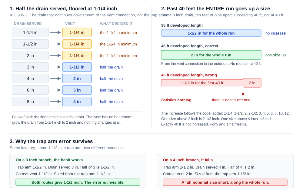
Two qualifications sit on that chart and both change answers.
The drain in question is the one that continues downstream of the point where the vent and the fixture drain connect, and its required size comes from Table 710.1(2). It is not the trap arm, not the fixture outlet, and not necessarily the pipe that is installed. An oversized installed drain returns an oversized vent, which is permitted but is a decision rather than an accident.
And the chart gives the base size only. If the developed length of the vent exceeds 40 feet, every one of those answers moves up a nominal size. The chart is where the calculation starts, not where it ends.
This method uses no fixture units at all. If you are sizing an individual or branch vent and something is asking you for a drainage fixture unit total, it is applying the wrong section.
The 40 Foot Vent Rule
One sentence in Section 906.2 decides more vent sizes than any other: vents exceeding 40 feet in developed length shall be increased by one nominal pipe size for the entire developed length of the vent pipe.
Three details separate a correct application from a plausible one.
The first is the word entire. The increase covers the whole run, from the vent connection to the termination, not the portion beyond 40 feet. There is no reducer at the 40 foot mark and no short length of larger pipe at the end. A vent installed at 1-1/2 inch for the first 40 feet with 2 inch beyond it satisfies nothing.
The second is the word exceeding. A run of exactly 40 feet, which is 12.19 m, is not increased. A run of 40 and a half feet is. A calculation that fires at or above 40 feet returns a size larger than the code requires, and on a marginal run that is a real cost difference.
The third is the ladder. The increase moves one step along the code vent sizes, which are the vent diameter columns of Table 906.1: 1-1/4, 1-1/2, 2, 2-1/2, 3, 4, 5, 6, 8, 10 and 12 inch. One size above 2 inch is 2-1/2 inch, not 3 inch, and one size above 4 inch is 5 inch, not 6 inch. A tool stepping through a general plumbing size list that omits 2-1/2 and 5 will return a size too large every time the increase starts from either of those.
The rule also interacts with how the length is measured, which is covered in its own section below. Measure along the wrong path and a run that is really 45 feet reads as 35, the increase never fires, and the vent goes in one size short.
One boundary worth stating. On this page the increase is applied to the Section 906.2 path. Stack vents and vent stacks are sized from Table 906.1, which already selects the diameter by developed length, so adding an increase there would count the same length twice. If a local jurisdiction reads the rule as applying to stack vents as well, that local requirement governs.
Vent Pipe Size Versus Trap Arm Size
This is the most common error on the subject, and it survives because it usually gives the right answer.
The trap arm is the horizontal pipe from the trap weir to the vent connection. It is the pipe the vent is physically nearest, it is the pipe in front of the plumber at the moment the vent is being fitted, and it is not the sizing input. Neither is the fixture outlet or the fixture drain.
The code documentation states it plainly: the vent size is not based on the trap or fixture drain, but on the drain size that continues downstream from the point where the vent and fixture drain connect.
Here is why the mistake lasts. A lavatory typically has a 1-1/2 inch trap arm. If it drains into a 3 inch branch, the correct vent is half of 3, which is 1-1/2 inch. Size it from the trap arm and you get 1-1/2 inch as well. The habit is confirmed every time, and nothing goes wrong.
Then the same lavatory drains into a 4 inch branch. The correct vent is half of 4, which is 2 inch. Size it from the trap arm and you fit 1-1/2 inch, a full size short, and the reason the error was invisible for years is that the two numbers happened to agree.
There is a second version of the same trap. Section 906.2 asks for the required diameter of the drain served, from Table 710.1(2), not the diameter of the pipe that happens to be installed. Where a drain was oversized for future capacity, sizing the vent from the installed pipe returns a larger vent than the code demands.
This calculator therefore asks for the drain served in those exact words, accepts the trap arm size only so it can confirm the trap arm was not used, and warns when the two differ. The distance from the trap to the vent is a separate question governed by Table 909.1, and that is a different calculation.
Developed Length for Vent Pipes
Developed length decides whether the 40 foot increase applies, so measuring it along the wrong path changes the answer. The code gives two different definitions and which one applies depends on the vent type.
For individual vents, branch vents, circuit vents and relief vents, Section 906.3 measures the developed length from the farthest point of vent connection to the drainage system, to the point of connection to the vent stack, stack vent, or termination outside the building. The measurement starts at the far end of the vent branch and ends where the vent leaves the system.
For Table 906.1, the note under the table measures the developed length from the vent connection to the open air. That path ends outdoors, not at a connection to another vent.
Where stack vents and vent stacks connect into a common vent header extending to the open air at one point, the developed length is the longest vent length from the intersection at the base of the most distant stack to the vent terminal, taken as a direct extension of one stack.
Developed length is the length along the pipe, following its actual route, not the straight line distance between its ends. On a run with several offsets the developed length can be considerably longer than the plan dimension suggests, and that is often what pushes a vent past 40 feet without anyone noticing.
The practical consequence is worth stating twice. A run measured from the wrong end, or measured as a straight line, can read as 35 feet when it is really 45. The 40 foot increase never fires, and the vent is installed one nominal size smaller than the code requires along its whole length.
Stack Vent Versus Vent Stack
The two terms sound interchangeable and they describe different pipes with different jobs.
A stack vent is the extension of a drainage stack above the highest horizontal drain connected to it. The same pipe carries waste below that point and air above it, and it continues to the outdoors as the vent terminal.
A vent stack is a separate dry vertical pipe that runs alongside a drainage stack and carries no waste at all. Its job is to relieve the pressures that build in the drainage stack as water falls through it. It connects at or below the lowest horizontal branch, and where it connects to the building drain, the connection is downstream of the drainage stack and within a distance of ten times the diameter of the drainage stack.
Both are sized the same way, under Section 906.1 from Table 906.1, on the diameter of the soil or waste stack, the total drainage fixture units connected, and the developed length. That is a different method from the half diameter rule used for individual and branch vents, and it uses inputs that method never touches.
The part that catches people is what happens after the table. The code does not stop at the table figure. It adds that in no case shall the diameter be less than one half the diameter of the drain served, and in no case less than 1-1/4 inch. All three apply and the answer is the largest of them, so a table lookup on its own is not the answer.
The published example in the ICC commentary shows both landing in the same place. A 3 inch soil stack, whose stack vent serves as the required vent extension to the outdoors and connects to a 3 inch building drain, needs at least a 1-1/2 inch stack vent, good for a maximum of 102 fixture units and a maximum 25 foot developed length. That 1-1/2 inch is also exactly half the 3 inch drain. It is a useful example and a treacherous one, because a tool implementing only one of the two rules looks correct on it.
This calculator carries the full Table 906.1, all thirty-eight rows, and applies the half diameter rule and the 1-1/4 inch minimum on top of the figure it reads. It selects the row on the fixture unit ceiling and the column on the developed length, and it does not interpolate between rows or extend the table past its last published row. Where a load or a run falls outside the table it says so and returns no diameter, because the table is a set of published cases rather than a curve.
When a Vent Stack or Relief Vent Is Required
Part of vent design is not a diameter at all, and no sizing table will reveal it.
Section 904.1 requires the vent system serving each building drain to have not less than one vent pipe extending to the outdoors, sized under Section 906.2 from the required size of the building drain. Every building drain needs at least one path to open air.
Section 904.2 requires a vent stack for every drainage stack that has five branch intervals or more. The threshold has a reason rather than being arbitrary: below five branch intervals the pressure in the drainage stack is not likely to create a pressure differential at the trap seals in excess of 1 inch of water column, which is the margin the whole vent system exists to protect. At five intervals and above, the stack needs its own dry relief path.
Section 908.1 adds relief vents for soil and waste stacks in buildings having more than 10 branch intervals, installed at each tenth interval beginning with the top floor. Note the wording: more than ten, so a stack with exactly ten does not trigger it. Section 908.2 then sets the size, equal to the vent stack the relief vent connects to.
None of these produces a number. A design where every vent diameter is correct and a required vent stack is missing does not comply, and the failure will not show up in any diameter check.
This calculator reports these requirements in a block separate from the diameter, so nobody reads the branch interval count as something that changed the pipe size. Where the count is not entered, it reports the check as not evaluated rather than staying silent, because silence on a requirement reads as an absence of one.
What Is Vent Pipe Sizing
A drainage system needs air as much as it needs fall. Water moving down a drain pushes air ahead of it and pulls air behind it, and if that air cannot get in and out freely the pressure swings either blow the water out of a trap seal or siphon it out. Either way the seal is lost and the drain becomes an open pipe between the sewer and the room. The vent system is what keeps the pressure at every trap within about an inch of water column of atmospheric, which is the margin the code is protecting.
Vent pipe sizing is deciding the diameter of those air paths. It is a separate calculation from drain sizing and it starts from the drain rather than from anything about the vent, which is the part that surprises people. The code sets the vent at half the required diameter of the drain that continues downstream of the vent connection, with an absolute floor of 1-1/4 inch, and then adjusts for how far the vent has to run.
Length matters here in a way it does not for a fixture drain. A vent is a low pressure air path and friction along it costs the pressure margin the system depends on, so once the developed length passes 40 feet the code takes back the loss by adding a nominal size to the whole run.
The rest of Section 906 handles the vertical side, and the third method in that section handles building sumps from an entirely different input, the pump capacity in gallons per minute.
Key Facts
- Individual, branch, circuit and relief vents are sized under IPC Section 906.2, Vents other than stack vents or vent stacks, at not less than one half the required diameter of the drain served, with the required drain size taken from Table 710.1(2).
- Vent pipes shall be not less than 1-1/4 inches, which the code prints as 32 mm and which converts exactly to 31.8 mm. That floor governs for every drain of 2 inch and smaller.
- The ladder this produces: a 4 inch drain takes a 2 inch vent, a 3 inch drain takes 1-1/2 inch, a 6 inch drain takes 3 inch, an 8 inch drain takes 4 inch, and anything 2 inch or smaller takes the 1-1/4 inch minimum.
- Vents exceeding 40 feet, which the code prints as 12 192 mm, in developed length are increased by one nominal pipe size for the entire developed length of the vent pipe.
- The nominal vent size ladder is the vent diameter column set of Table 906.1: 1-1/4, 1-1/2, 2, 2-1/2, 3, 4, 5, 6, 8, 10 and 12 inch. One size up from 2 inch is 2-1/2 inch and one size up from 4 inch is 5 inch.
- Stack vents and vent stacks are sized under Section 906.1 from Table 906.1 on the developed length and the total drainage fixture units connected, and in no case less than half the diameter of the drain served or less than 1-1/4 inches.
- Developed length is measured differently by vent type. For individual, branch, circuit and relief vents, Section 906.3 measures from the farthest point of vent connection to the drainage system to the point of connection to the vent stack, stack vent or outdoor termination. For Table 906.1 it is measured from the vent connection to the open air.
- The vent size is not based on the trap or the fixture drain. It is based on the drain size that continues downstream from the point where the vent and the fixture drain connect.
- Section 904.1 requires the vent system serving each building drain to have not less than one vent pipe extending to the outdoors, sized under Section 906.2 from the required size of the building drain.
- Section 904.2 requires a vent stack for every drainage stack that has five branch intervals or more. Below that the pressure in the stack is not likely to create a differential at the trap seals exceeding 1 inch of water column.
- Section 908.1 requires relief vents for soil and waste stacks in buildings having more than 10 branch intervals, at each tenth interval installed, beginning with the top floor. Exactly ten does not trigger it. Section 908.2 then sets the relief vent equal in size to the vent stack it connects to.
- A vent stack connects at or below the lowest horizontal branch, and where it connects to the building drain the connection is downstream of the drainage stack and within a distance of 10 times the diameter of the drainage stack.
- Individual vents may merge with each other under Section 905.5 provided the connection is at least 6 inches, which is 152 mm, above the flood level rim of the highest fixture served.
- Where stack vents and vent stacks connect into a common vent header extending to the open air at one point, the header is sized under Section 906.1 with the fixture units summed across all stacks and the developed length taken as the longest vent length from the base of the most distant stack to the terminal. This is a code rule to check on a stack vent system rather than a general merged vent layout method, and this page does not design merged arrangements.
- Section 906 contains a third sizing method that this page does not use: Section 906.5.1 sizes building sump vents from Table 906.5.1 on the pump capacity in gallons per minute and the developed length.
- Local jurisdictions amend both the numbering and the requirements. Chicago carries the same rule as Section 18-29-916.1 with a correspondingly renumbered table, and Philadelphia requires a full size vent where the piping is part of a single stack vent system.
Applications
- A plumber roughing in a bathroom group needs the vent size for a lavatory and has the trap arm in front of him, which is the wrong pipe to measure. This page asks for the drain that continues downstream instead and says why.
- A designer laying out a long horizontal branch checks whether the vent run passes 40 feet, because that single threshold changes the size of the entire vent rather than the far end of it.
- A designer rechecks a vent that looked acceptable at 39 feet on the plan, after fittings and offsets pushed the developed length past 40 feet on site, and finds the whole run has to move up a nominal size.
- An engineer working a multi storey building checks the branch interval count to see whether a vent stack is required at all, which is a requirement no diameter calculation would reveal.
- A contractor pricing a job finds out early that a 4 inch branch needs a 2 inch vent rather than the 1-1/2 inch that matches the trap arm, before the pipe is ordered.
- A plans reviewer checks that a submitted vent size came from the drain served rather than from the fixture drain, and that the 40 foot increase was applied across the whole run rather than at the end of it.
- A designer sizing a stack vent confirms that the table figure was checked against the half diameter rule, since the code applies both and takes the larger.
Example Calculations
Example 1. The basic ladder
Given: an individual vent serving a lavatory that drains into a 3 inch branch. Developed length 20 feet.
Half of 3 inch is 1-1/2 inch, which is above the 1-1/4 inch minimum, so the vent is 1-1/2 inch. That is 38.1 mm. The developed length is under 40 feet, so no increase applies.
Result: a 1-1/2 inch vent. For comparison, a 4 inch drain would take 2 inch, a 6 inch drain 3 inch, and an 8 inch drain 4 inch.
Example 2. The floor governs
Given: an individual vent serving a fixture on a 2 inch drain, 20 feet developed length.
Half of 2 inch is 1 inch, which is below the code minimum. The vent is 1-1/4 inch, which is 31.8 mm.
Result: 1-1/4 inch, and the floor decided it rather than the drain. That distinction matters in a redesign, because a vent at the floor has no headroom: if the drain grows to 3 inch the vent moves to 1-1/2 inch, but if it grows from 1-1/4 to 2 inch nothing changes at all.
Example 3. Ten feet of pipe changes the whole vent
Given: the 3 inch drain from Example 1, first at 35 feet developed length and then at 45 feet.
At 35 feet the vent is 1-1/2 inch and nothing else applies. At 45 feet the developed length exceeds 40 feet, so the code increases the vent by one nominal size for the entire developed length. The vent becomes 2 inch.
Result: 1-1/2 inch becomes 2 inch, and it is 2 inch from the connection to the outdoors. There is no reducer at the 40 foot mark and no short length of larger pipe at the end.
Example 4. Exactly 40 feet
Given: the same 3 inch drain at exactly 40 feet developed length, and then at 40 and a half feet.
At exactly 40 feet the vent stays 1-1/2 inch. The code says exceeding 40 feet, and 40 is not more than 40. At 40 and a half feet the increase fires and the vent becomes 2 inch.
Result: half a foot of pipe changes the size of the entire run. A calculation that triggers at or above 40 feet returns 2 inch in both cases, which is a size larger than the code requires on the first one.
Example 5. The increase follows the code ladder, not a generic one
Given: a 4 inch drain with a vent run of 60 feet.
Half of 4 inch is 2 inch. The run exceeds 40 feet, so one nominal size is added. The Table 906.1 ladder runs 1-1/4, 1-1/2, 2, 2-1/2, 3, 4, 5, 6, 8, 10, 12, so the size above 2 inch is 2-1/2 inch.
Result: 2-1/2 inch, which is 63.5 mm. A calculation using a general plumbing size list that skips 2-1/2 inch would return 3 inch, a size larger than the code requires. The same trap sits above 4 inch, where the next size is 5 inch rather than 6 inch.
Example 6. Both rules apply in sequence
Given: a fixture on a 2 inch drain with a 45 foot vent run.
Half of 2 inch is 1 inch. The floor lifts it to 1-1/4 inch. The length then lifts it again to 1-1/2 inch.
Result: 1-1/2 inch, from a 2 inch drain. Two separate rules acted, in order, and neither on its own would have produced that answer.
Example 7. The trap arm is not the input
Given: a lavatory with a 1-1/2 inch trap arm, draining into a 4 inch branch.
The vent is sized from the 4 inch branch, so half of 4 is 2 inch.
Result: a 2 inch vent beside a 1-1/2 inch trap arm. A plumber sizing from the pipe in front of him fits 1-1/4 or 1-1/2 inch and is a size or two short. The coincidence that hides this error is the 3 inch case: there, half the drain is 1-1/2 inch and the trap arm is often 1-1/2 inch too, so sizing from the wrong pipe gives the right answer and the habit survives until it meets a 4 inch branch.
Example 8. Required drain size against installed drain size
Given: a fixture group whose required drain size from Table 710.1(2) is 3 inch, installed in 4 inch pipe because the branch was oversized for future capacity.
Sized from the required 3 inch drain, the vent is 1-1/2 inch. Sized from the installed 4 inch pipe, the vent is 2 inch.
Result: two defensible answers and one decision to make. Section 906.2 refers to the required diameter, so 1-1/2 inch satisfies the model code. Some authorities having jurisdiction and some project specifications require sizing from the installed pipe, in which case 2 inch applies. What matters is that the basis is chosen deliberately rather than by whichever number happened to be on the drawing.
Example 9. Some of the answer is not a size
Given: a drainage stack serving six branch intervals, with vents sized correctly throughout.
Section 904.2 requires a vent stack for every drainage stack of five branch intervals or more. Six triggers it. Had the building had four, no vent stack would be required, because below five intervals the pressure in the stack is not expected to create a differential at the trap seals exceeding 1 inch of water column.
Result: a vent stack is required, and no amount of correct pipe sizing substitutes for it. Above ten branch intervals, Section 908.1 adds relief vents on top. Exactly ten does not, since the code says more than ten.
Example 10. Reading Table 906.1, and why the table alone is not the answer
Given: a stack vent on a 3 inch soil stack carrying 10 drainage fixture units, 20 feet of developed length, connecting to a 3 inch building drain.
The table row for a 3 inch stack up to 10 dfu allows 42 feet in the 1-1/2 inch column, so 1-1/2 inch covers a 20 foot run. Half the 3 inch drain served is also 1-1/2 inch. The 1-1/4 inch minimum is already met.
Result: 1-1/2 inch. This is the published ICC commentary case, and both rules land on the same number, which is exactly why it is a poor test of an implementation. A tool that reads only the table passes it. So does a tool that applies only the half diameter rule.
Example 11. The same table row, a longer run
Given: the same 3 inch stack and 10 fixture units, now with 400 feet of developed length.
The columns in that row are 1-1/2 inch to 42 feet, 2 inch to 150 feet, 2-1/2 inch to 360 feet and 3 inch to 1,040 feet. The smallest column that covers 400 feet is 3 inch.
Result: 3 inch, from the table. Half the drain served is still 1-1/2 inch, so the table governs here and the two rules have parted company. Note that the 40 foot increase from Section 906.2 is not applied on top: the table has already selected the diameter by developed length, and applying the increase as well would count the same length twice and return 4 inch where the code requires 3.
Example 12. The table figure is short
Given: a vent stack on a 6 inch stack carrying 500 fixture units over 20 feet, where the drain served is 12 inch.
The table gives 3 inch. Half the drain served is 6 inch. Section 906.1 requires the largest of the table figure, half the drain served and 1-1/4 inch.
Result: 6 inch, and the table did not decide it. A tool that reads the table and stops there fits a 3 inch vent, three sizes short. This is the case Example 10 cannot catch.
Example 13. Outside the table
Given: a stack vent on a 3 inch stack with 200 fixture units, and separately, the same stack at 10 fixture units with an 1,100 foot run.
The last row published for a 3 inch stack covers 102 dfu, so 200 has no row. The largest column in the 10 dfu row is 3 inch at 1,040 feet, so 1,100 feet has no column.
Result: no diameter in either case. The first is a drainage stack problem rather than a vent problem, since Table 710.1(2) caps what a 3 inch stack may carry, and the vent is read from the larger stack group once the stack grows. The second is a routing problem: the code has no larger vent to offer in that row, so the run has to reach open air sooner.
Standards & References
- 2024 International Plumbing Code, Chapter 9, Vents Contains Section 904 for the vent system requirements including the five branch interval trigger, Section 905.5 for merging individual vents, Section 906.1 for stack vents and vent stacks with Table 906.1, Section 906.2 for individual, branch, circuit and relief vents including the half diameter rule, the 1-1/4 inch minimum and the 40 foot increase, Section 906.3 for how developed length is measured, Section 906.5.1 for building sump vents, and Section 908 for relief vents.
- IPC Section 906.2, Vents other than stack vents or vent stacks The section carrying the half diameter rule, the 1-1/4 inch minimum vent size and the 40 foot developed length increase. Its wording was confirmed against the code text: the diameter of individual vents, branch vents, circuit vents and relief vents shall be not less than one-half the required diameter of the drain served, vent pipes shall be not less than 1-1/4 inches, and vents exceeding 40 feet in developed length shall be increased by one nominal pipe size for the entire developed length.
- IPC Section 906.1, Size of stack vents and vent stacks The stack path, with Table 906.1 and the two floors the code applies on top of it: in no case shall the diameter be less than one-half the diameter of the drain served or less than 1-1/4 inches. The vent diameter columns of Table 906.1 run 1-1/4, 1-1/2, 2, 2-1/2, 3, 4, 5, 6, 8, 10 and 12 inch, which is the ladder the 40 foot increase steps along.
- 2024 International Plumbing Code, Chapter 7, Sanitary Drainage Contains Section 710.1 and Table 710.1(2), which is where the required diameter of the drain served comes from, and Table 709.1 for the drainage fixture unit values behind it.
- IPC Section 710.1, Maximum fixture unit load Table 710.1(2) gives the maximum drainage fixture units for a given size of horizontal branch or vertical soil or waste stack, which is the required drain size this calculator asks for.
- ICC Building Safety Journal, Methods of venting plumbing fixtures and traps in the 2021 IPC The source of the worked ladder used on this page and of the statement that the vent size is not based on the trap or fixture drain but on the drain continuing downstream of the connection. It carries the published example of a 3 inch soil stack whose stack vent needs at least 1-1/2 inch, good for a maximum of 102 fixture units and a maximum 25 foot developed length.
- IPC Section 908, Relief vents, stacks of more than 10 branch intervals Section 908.1 requires soil and waste stacks in buildings having more than 10 branch intervals to be provided with a relief vent at each tenth interval installed, beginning with the top floor. Section 908.2 sets the size of the relief vent equal to the vent stack to which it connects.
Units
Diameters are entered and reported in inches with millimetres alongside. Convert with 1 inch equal to 25.4 mm, so 1-1/4 inch is 31.8 mm, 1-1/2 inch is 38.1 mm, 2 inch is 50.8 mm, 2-1/2 inch is 63.5 mm, 3 inch is 76.2 mm and 4 inch is 101.6 mm. Nominal pipe sizes stay in inches in both unit systems, because that is how vent pipe is specified, ordered and inspected wherever this code applies, and the code itself prints the metric figures as conversions beside the inch sizes rather than as separate sizes. Length is entered in feet or metres, with 1 foot equal to 0.3048 m, so the 40 foot threshold is 12.19 m and the code prints it as 12 192 mm. The 6 inch merging height above the flood level rim is 152 mm. Drainage fixture units are dimensionless and identical in both systems, as is the branch interval count. The internal unit selector governs the fields, labels, math, on-screen result and any exported result, and it takes priority over any site-wide unit switch. Switching converts the values you entered rather than reinterpreting them, so 40 feet becomes 12.19 m and returns to exactly 40 feet when switched back.
Limitations
- This calculator sizes vent diameter under IPC Section 906. It does not size wet vents, common vents, air admittance valves, single stack or reduced size venting systems, or combination waste and vent systems. Those are arrangement specific rules rather than diameter sizing, and a diameter from Section 906.2 does not prove that the venting arrangement itself is permitted.
- It does not cover vent terminal location, roof penetration, or the increased terminal size some jurisdictions require against frost closure.
- It does not size building sump vents. Section 906.5.1 handles those from Table 906.5.1 on the pump capacity in gallons per minute and the developed length, which is a different input entirely.
- It does not give the maximum distance from a trap to its vent. That is Table 909.1 and a separate calculation.
- The stack vent and vent stack path reads Table 906.1 as printed, including its quirks: blank cells are diameters the table does not publish for that row rather than zero capacity, and figures such as 729 feet and 571 feet are transcribed rather than rounded. The calculator does not interpolate between rows, extend the table past its last published row, or apply the Section 906.2 length increase on top of it. A load or a run outside the table returns a state rather than a diameter.
- The 40 foot increase is applied to the Section 906.2 path only. The sentence sits inside 906.2, and Table 906.1 already selects the diameter on developed length, so applying both would count the same length twice. If your jurisdiction reads the increase as applying to stack vents as well, that governs.
- The input is the code required diameter of the drain served, from Table 710.1(2), not necessarily the pipe that is installed. Where an installed drain is larger than the code requires, entering the installed size returns a larger vent than the code demands. That is not an error, but it should be a decision rather than an accident, and where the authority having jurisdiction requires the installed size, that governs.
- Developed length must be measured along the path the code specifies for the vent type being sized, and the two definitions differ. Measuring the wrong path can change whether the 40 foot rule applies.
- Section numbers and requirements are amended locally. The numbering here follows the model code, and the two amendment options are illustrations that amendments are real rather than a list to rely on.
- The modelled sizes are the vent diameter columns of Table 906.1 up to 12 inch, with 15 inch accepted as a drain served. A design that runs past the top of that ladder returns a state rather than an invented diameter.
Common Mistakes to Avoid
- Sizing the vent from the trap arm. The trap arm is the pipe the vent is physically nearest and it is the wrong input. The vent comes from the drain that continues downstream of the point where the vent and the fixture drain connect.
- Sizing the vent from the fixture drain or the fixture outlet. Same error, different pipe. A 1-1/4 inch lavatory outlet on a 4 inch branch still takes a 2 inch vent.
- Applying the 40 foot increase to the far end of the run. The code increases the entire developed length by one size. There is no reducer at the 40 foot mark and no short length of larger pipe at the end.
- Triggering the increase at exactly 40 feet. The code says exceeding 40 feet, so a run of exactly 40 feet is not increased. A calculation that fires at or above 40 returns a size too large.
- Stepping up through a generic pipe size list. The vent ladder includes 2-1/2 inch and 5 inch, so one size above 2 inch is 2-1/2 inch and one size above 4 inch is 5 inch. A general list that skips them returns a larger size than the code requires.
- Measuring developed length as a straight line. It follows the actual route of the pipe, so a run with several offsets can be considerably longer than the plan dimension suggests, and that is often what pushes a vent past 40 feet unnoticed.
- Using the installed drain size instead of the required one. Section 906.2 asks for the required diameter from Table 710.1(2). An oversized installed drain returns an oversized vent.
- Reading the Table 906.1 figure as the final answer for a stack vent. The code applies the half diameter rule and the 1-1/4 inch minimum on top of the table and takes the largest of the three.
- Forgetting that a vent stack may be required regardless of size. Five branch intervals or more triggers one under Section 904.2, and no amount of correct pipe sizing substitutes for it.
- Applying Section 906.2 to a wet vent or a common vent. Wet venting and common venting are arrangement specific methods with their own rules. A diameter from Section 906.2 does not prove that the venting arrangement itself is permitted.
- Measuring developed length along the wrong path. Individual vents measure to the vent stack, stack vent or outdoor termination. Table 906.1 measures to the open air. The difference can decide whether the 40 foot rule applies.
- Assuming the section number is the same everywhere. Chicago numbers the same requirement 18-29-916.1, and other jurisdictions amend the requirement itself rather than just the number.
Frequently Asked Questions
What size vent pipe do I need?
Is the vent sized from the trap arm?
What is the 40 foot rule for vent pipes?
Does the 40 foot rule apply at exactly 40 feet?
Does the 40 foot rule apply to stack vents and vent stacks?
What is the minimum vent pipe size?
How do I size a vent stack or a stack vent?
What is the difference between a stack vent and a vent stack?
When is a vent stack required?
How is developed length measured for a vent?
What if my installed drain is larger than the required drain?
Can this calculator size a wet vent?
What size vent is required for a building sump?
Frequently Used Together
Engineers often use these calculators in combination for complete project workflows:
Related Calculators
Explore similar calculators that might be useful for your project:
Plumbing Quick Reference — Keep It On Your Phone On Site
A 10-page field reference for catching pressure, velocity, slope, and pump-sizing mistakes before you order pipe, close a wall, or add a booster.
- Velocity limits, fixture pressure minimums, drain slope, and the 80 psi ceiling in one table
- Worked examples that show why a single pressure number gives four different answers
- Keep it on your phone, or print the two field-check pages
Free PDF. Calculators stay free. Unsubscribe anytime.
Calculate
This selector governs every field, label, result and export on this page, and it takes priority over the site header switch. Switching converts the developed length you entered rather than reinterpreting it, so 40 ft becomes 12.19 m and returns to exactly 40 ft when you switch back. Nominal pipe sizes stay in inches in both systems, with millimetres alongside, because that is how vent pipe is specified, ordered and inspected. Drainage fixture units are dimensionless and identical in both systems.
Vent Type
Choose this first. Section 906 contains two sizing methods that take entirely different inputs and even measure the developed length differently. Individual, branch, circuit and relief vents are sized under Section 906.2 from the drain served, with no fixture units at all. Stack vents and vent stacks are sized under Section 906.1 from Table 906.1 on the stack diameter, the fixture unit total and the developed length.
The Drain the Vent Is Sized From
The drain that continues downstream of the point where the vent and the fixture drain connect. This is the code required drain size, from Table 710.1(2) or from a drain sizing calculation. It is not the trap arm, not the fixture outlet, and not an oversized installed pipe unless your authority having jurisdiction requires the installed size. Stack vents and vent stacks need this figure too, because the code applies a half diameter floor on top of the table.
For individual, branch, circuit and relief vents, Section 906.3 measures from the farthest point of vent connection to the drainage system, to the point of connection to the vent stack, stack vent or outdoor termination. For Table 906.1 it is measured from the vent connection to the open air. It follows the actual route of the pipe rather than a straight line, so a run with several offsets is longer than the plan dimension suggests.
Stack Vents and Vent Stacks Only
Table 906.1 is keyed on this together with the fixture unit total. Leave it alone for an individual, branch, circuit or relief vent, which is sized from the drain served and never from the stack.
The drainage fixture unit total being vented, which is the second key into Table 906.1. Section 906.2 uses no fixture units at all, so if you are sizing an individual or branch vent and something is asking you for a fixture unit total, it is applying the wrong section.
Optional Checks (none of these block Calculate)
Enter this and the calculator reports whether Section 904.2 requires a vent stack and whether Section 908.1 requires relief vents. Neither is a diameter and neither changes the size, so they appear in their own block. Left blank, the check is reported as not evaluated rather than staying silent, because silence on a requirement reads as an absence of one.
Entered only so the calculator can confirm the trap arm was not used, and warn you when it differs from the drain served. That difference is where the classic sizing error lives: a lavatory with a 1-1/2 inch trap arm on a 4 inch branch takes a 2 inch vent, not a 1-1/2 inch one. The distance from the trap to the vent is a separate question governed by Table 909.1.
Amendments are advisory by default and never change a result unless you select one. Philadelphia amends the rough-in provision to require a full size vent where the drainage piping is part of a single stack vent system. Chicago carries the same requirement as Section 18-29-916.1 with a correspondingly renumbered table, so the size is unchanged and only the citation differs.