Sanitary Drain Pipe Sizing Calculator — DFU to Pipe Size
On this page
Calculate
Sets all diameter and slope labels. Drainage fixture units are dimensionless and do not change between unit systems. Switching converts displayed diameters rather than reinterpreting them.
The code uses a different capacity table for each part of the system. The same DFU load can need a 4 inch horizontal branch but only a 3 inch building drain, because building drains are sized from a different table.
The total drainage fixture unit load carried by this pipe. If you do not know it, count it in the Drainage Fixture Unit Calculator first.
Any drain serving a water closet is at least 3 inches, regardless of the DFU load. This overrides the table, so answer it for every run. There is no default.
Overview
Sanitary drain pipe size is not read from a single chart. The code sizes a drain from its drainage fixture unit load, but which capacity table applies depends on what the pipe is: a horizontal fixture branch, a vertical soil or waste stack, or a building drain running out to the sewer. A DFU total alone is not enough. You also need to know where the pipe sits in the drainage system.
The clearest example is a load of 26 DFU. As a horizontal fixture branch it needs 4 inches, and as a building drain at a quarter inch per foot it needs just 3 inches. The branch needs the larger diameter for an identical load, because the code sizes each part of the system from a different table rather than a single universal chart.
Slope enters the picture for building drains and sewers. The code gives four grade columns, and capacity rises with grade: a 4 inch drain carries 180 DFU at an eighth inch per foot and 250 DFU at a half inch per foot. Laying the same drain one step steeper can save a whole pipe size.
Stacks work differently again, because a stack has two limits that must both be satisfied. There is a total for the whole stack, and there is a much smaller limit on how much load can discharge into any single branch interval. A 4 inch stack accepts 240 DFU in total but no more than 90 into one interval, so a busy single floor can force a larger stack than the building total suggests.
This calculator takes the DFU load and returns the minimum diameter, naming the table and column it used. Counting the DFU load itself is the Drainage Fixture Unit Calculator. Setting the grade and the fall once the diameter is known is the Drain Pipe Slope Calculator. The three run in sequence: count the load, size the pipe, set the grade.
What to Look at First
Choose the application first: it determines which code table is used. A horizontal fixture branch, a vertical stack, and a building drain do not share the same capacity table, so the same DFU load gives different pipe sizes. A load of 26 DFU needs 4 inches as a branch but only 3 inches as a building drain at a quarter inch per foot.
The result shows the minimum diameter, the table and column used, and which rule governed. If the water closet minimum raised the size above what the load required, the result names the table-only size. If the branch interval limit governed on a stack, the result says so and names the interval load that controlled.
For building drains, the slope is part of the sizing answer. A steeper grade means more capacity: a 4 inch drain carries 180 DFU at an eighth inch per foot and 250 DFU at a half inch per foot. A load of 200 DFU needs 5 inches at the shallower grade but only 4 inches at the steeper one.
The next size down tells you how close you are to a size boundary. If it shows a capacity, you can see the margin. If it shows "not listed at this slope", that diameter is blank in the code column, meaning the code does not permit it at that grade (not that its capacity is zero).
How to Use This Calculator
Choose your unit system with the calculator's own selector. Drainage fixture units are dimensionless and identical in both systems. Only the diameter and slope labels change units.
Choose the application: horizontal fixture branch, vertical soil or waste stack, or building drain and building sewer. This is the most important choice on the page, because it decides which code table is used.
Enter the DFU load carried by this pipe. If you do not know it, count it in the Drainage Fixture Unit Calculator first.
Answer whether the run serves a water closet. There is no default, because the answer changes the result: any drain serving a water closet is at least 3 inches regardless of the load.
For a building drain, pick the slope from the dropdown. It offers only the four grades the code table lists. If you need an arbitrary grade or the fall across a run, use the Drain Pipe Slope Calculator instead.
For a stack, enter both the total load and the load discharging into the largest single branch interval, and choose whether the stack has three branch intervals or less, or more than three. A stack cannot be sized from the total load alone.
Read the result. You get the minimum diameter, the table and column used, the capacity of that size, the capacity of the next size down, and which rule governed the answer.
This calculator sizes one pipe segment at a time from a DFU load. Counting the DFU load is the Drainage Fixture Unit Calculator. Setting the grade and fall once the diameter is known is the Drain Pipe Slope Calculator. The three run in sequence.
Inputs & Outputs
Inputs
System Setup
Required Inputs (All Applications)
Building Drain Inputs
Stack Inputs
Outputs
Primary Result
Governing Rule
Notes
Formula
This calculator applies IPC Table 710.1 as a code table lookup, not an algebraic formula. The complete step-by-step decision logic is in the Sanitary Drain Pipe Sizing Formula section below.
Sanitary Drain Pipe Sizing Formula
Drain sizing is a code table lookup, not an equation. There is no expression that turns DFU into a diameter. The pipe size is the smallest listed diameter whose capacity is at or above the load, in the table and column that match the application.
1. Choose the table from the application

   horizontal fixture branch -> Table 710.1(2), horizontal branch column
   stack                     -> Table 710.1(2), stack columns
   building drain or sewer   -> Table 710.1(1), column for the slope

2. Horizontal fixture branch

   size = smallest diameter where branch_capacity >= dfu_load

3. Stack, two independent limits, BOTH must be satisfied

   size_a = smallest diameter where one_interval_capacity >= dfu_largest_interval
   size_b = smallest diameter where stack_total_capacity  >= dfu_load
            stack_total_capacity uses the 3-intervals-or-less column
            or the greater-than-3-intervals column
   size   = the LARGER of size_a and size_b

4. Building drain or building sewer

   size = smallest LISTED diameter in the slope column where capacity >= dfu_load
   a blank cell is skipped, it is not a capacity of zero

5. Water closet minimum (footnote a)

   if a water closet is served: size = max(size, 3 in)

6. Stack not smaller than its branches (footnote b)

   if a branch size was entered: size = max(size, largest_branch_size)

7. Stack reduction floor (footnote b)

   a stack may be reduced going up as accumulated load decreases,
   but never below one half of the largest required stack diameter

8. No reduction in the direction of flow (Section 704.2)

   a run downstream of this pipe is never smaller than this result
DECISION MODEL
1. Pick the table and column from the application
   horizontal branch  -> Table 710.1(2), horizontal branch column
   stack              -> Table 710.1(2), stack columns
   building drain     -> Table 710.1(1), column for the slope

2. Find the smallest listed diameter whose capacity is at or above the load.
   Skip blank cells: a blank means the code does not list that diameter
   at that slope, which is not the same as a capacity of zero.

3. For a stack, run that check twice: once for the single-interval limit
   and once for the stack total. Take the larger of the two sizes.

4. Raise to 3 inches if a water closet is served on this run.

5. Raise to the size of the largest horizontal branch connected to the stack,
   if one was entered.

6. Return no size if the load exceeds every listed capacity in the column.
   The tables stop at 15 inches. No extrapolation is performed.
DFU to Pipe Size by Application
There is no single DFU to pipe size chart in the code, and that is the most common misunderstanding about drain sizing. The International Plumbing Code separates the drainage system into three sizing situations, each with its own capacity table or column, and the same fixture unit load can land on three different diameters.
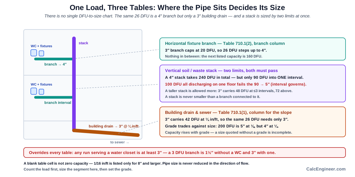
A horizontal fixture branch is read from Table 710.1(2), horizontal branch column. A vertical soil or waste stack is read from the stack columns of the same table, and it has to satisfy two limits rather than one. A building drain or building sewer is read from Table 710.1(1), using the column for the grade it is laid at.
Take 26 DFU. As a horizontal branch it needs 4 inches, because Table 710.1(2) lists a 3 inch branch capacity of 20 DFU and the next entry jumps to 160. As a building drain at a quarter inch per foot it needs only 3 inches, because Table 710.1(1) lists a 3 inch drain capacity of 42 DFU in the quarter-inch-per-foot column. The branch column is stricter because it reflects concentrated discharge close to the fixtures; the building drain column gives more capacity at the same diameter because the flow arrives spread over a long run on a controlled grade.
This is why the calculator asks for the application before anything else, and why the Drainage Fixture Unit Calculator hands off here rather than printing a final size. A DFU total is a load. It becomes a diameter only once you say where the pipe is.
Horizontal Fixture Branch Sizing
A horizontal fixture branch is the run that collects discharge from one or more fixtures and carries it to a stack or to the building drain. It is sized from the horizontal branch column of IPC Table 710.1(2), and it is the strictest of the three situations at small diameters.
The common sizes and their capacities:
| Diameter | Branch Capacity (DFU) |
|---|---|
| 1-1/2 in | 3 |
| 2 in | 6 |
| 2-1/2 in | 12 |
| 3 in | 20 |
| 4 in | 160 |
| 6 in | 620 |
| 8 in | 1,400 |
| 12 in | 3,900 |
The jump from 3 to 4 inches is the one that matters most in practice. A 3 inch branch tops out at 20 DFU, and the next size up carries 160, eight times as much. There is nothing in between, so a load of 21 DFU and a load of 150 DFU both land on 4 inches.
That steep step is also why the branch column is far less generous than the building drain column at the same nominal size. A 3 inch branch carries 20 DFU while a 3 inch building drain carries 42 DFU at a quarter inch per foot. A branch receives concentrated discharge from fixtures close together, without the smoothing that a long building drain gets from everything upstream of it.
Building Drain and Sewer Sizing by Slope
A building drain is the lowest horizontal piping inside the building that collects discharge from the stacks and branches and carries it out to the building sewer. Both are sized from IPC Table 710.1(1), which is built differently from the branch table: instead of one capacity per diameter, it gives four, one for each grade the code lists.
The grade columns are a sixteenth, an eighth, a quarter, and a half inch per foot. Capacity rises with grade, because a steeper pipe carries the same solids at a higher velocity in a shallower depth of flow. The 4 inch row shows it clearly:
| Diameter | 1/8 in/ft | 1/4 in/ft | 1/2 in/ft |
|---|---|---|---|
| 3 in | 36 DFU | 42 DFU | 50 DFU |
| 4 in | 180 DFU | 216 DFU | 250 DFU |
| 5 in | 390 DFU | 480 DFU | 575 DFU |
| 6 in | 700 DFU | 840 DFU | 1,000 DFU |
A load of 200 DFU therefore needs 5 inches at an eighth inch per foot but only 4 inches at a quarter, which is a real material saving on a long run.
Not every diameter appears at every grade. The sixteenth inch per foot column is blank for everything below 8 inches, because a small pipe laid that flat cannot maintain scouring velocity. A blank cell means the code does not list that diameter at that grade, which is a different statement from a capacity of zero. When a blank is reached, you move down the same column to the first diameter that is listed.
Sanitary Stack Sizing
A vertical soil or waste stack is sized from the stack columns of IPC Table 710.1(2), and it is the only application on this page with two limits that must both be satisfied.
The first limit is the total accumulated load on the stack. The second is the load discharging into any single branch interval. These are separate columns with very different numbers. A 4 inch stack of three branch intervals or less accepts 240 DFU in total, but no more than 90 DFU entering at any one interval.
The stack total also depends on the height of the stack. A stack of three branch intervals or less has a lower total limit than a taller one. A 3 inch stack carries 48 DFU at three intervals or less and 72 DFU above that. In a tall stack the falling water reaches terminal velocity and settles into a stable annular film against the pipe wall, with a continuous air core down the middle. A short stack never develops that pattern, so the code allows it less load.
Two more rules apply. A stack is never smaller than any horizontal branch connected to it, so a 4 inch branch forces at least a 4 inch stack whatever the load says. And a stack may be reduced in size going up as the accumulated load decreases, but never to less than half the diameter of the largest size the stack required lower down.
Branch Interval Limit
A branch interval is a length of stack, roughly one story tall, within which horizontal branches connect. The code counts them because both stack limits depend on them, and because the single interval limit is the one that most often decides the size.
Compare the two columns for a 4 inch stack of three branch intervals or less. The stack total is 240 DFU. The limit into a single branch interval is 90 DFU. The interval limit is less than half the total, and for a 6 inch stack the gap is wider still: 960 DFU total against 350 into one interval.
The reason is hydraulic. Water entering a stack at one point has to be absorbed into the falling film without sealing off the air core. Too much flow entering at a single level creates a hydraulic jump that can close the pipe, pressurize the section below, and blow or siphon trap seals on the nearby floors. Spreading the same total load over several intervals avoids that, which is why the code cares where the load enters and not just how much there is.
The practical consequence is that a single busy floor can drive the stack size for the whole building. A stack carrying 100 DFU in total passes the 4 inch limit of 240 with room to spare, but if all 100 DFU enter at one interval it fails the 90 DFU interval limit and the stack becomes 5 inches. Sizing a stack from the building total alone will understate it every time the load is concentrated.
Water Closet 3 Inch Minimum
The code sets a floor that overrides the capacity tables: the minimum size of any building drain serving a water closet is 3 inches. It applies regardless of the fixture unit load, and it is the reason this calculator asks whether a water closet is served rather than assuming an answer.
The effect is easiest to see on a small branch. A load of 3 DFU fits a 1-1/2 inch pipe exactly, since that is the listed capacity. Add a water closet to that same run and the size becomes 3 inches, twice the diameter for the same fixture unit count.
The reason is that fixture units describe average probable load, not the character of the discharge. A water closet releases a large volume of water and solids in a few seconds. A smaller pipe would carry the fixture unit load on paper but would not clear that slug reliably, and a blockage in a drain carrying soil is a different order of problem from one in a lavatory waste.
The calculator prints what the table alone would have allowed whenever this rule raises the size, so it is clear that the minimum governed rather than the capacity.
Drain Pipe Size and Slope
Diameter and grade are decided together for a building drain, which is why the slope appears as an input on a sizing page at all. The capacity table is indexed by both, so a size quoted without a grade is incomplete: 200 DFU is a 5 inch drain at an eighth inch per foot and a 4 inch drain at a quarter.
That trade runs in both directions. If the excavation depth is fixed and the grade has to stay shallow, the pipe grows. If the pipe size is fixed by what is already in the ground downstream, the grade has to be steep enough for that diameter to carry the load. Neither is decided first in practice; they are settled against each other.
This calculator handles the sizing half. It offers only the four grades the code table lists, because those are the columns the capacity values belong to, and interpolating between them is not something the table supports. If you need to work with an arbitrary grade, convert a percentage to inches per foot, or find the fall across a run of known length, that is the Drain Pipe Slope Calculator.
Use them together: size the pipe here from the load and a candidate grade, then take the diameter to the slope calculator to work out the actual fall over the run and confirm it fits the available depth.
Pipe Size Not Reduced in Direction of Flow
The code states plainly that the size of a drainage pipe is not reduced in the direction of flow. Whatever diameter a run reaches, everything downstream of it stays at least that size, even where the capacity table would allow something smaller.
This matters because the tables are read segment by segment. A branch might size to 3 inches on its own load, but if it connects downstream of a 4 inch run, it cannot step back down. A reduction in the direction of flow creates a bottleneck at the transition, where solids catch and the section upstream can surcharge.
There is a second rule about stacks that sounds like a contradiction but is not. A stack may be reduced in size going up, as the accumulated load decreases story by story, provided it never goes below half the largest diameter the stack required at its base. That reduction runs upward, against the direction of flow, so it does not conflict with the rule above. Water in a stack travels down, toward the larger pipe, never toward the smaller one.
The calculator returns a minimum for the segment you described, and it prints the reminder on every result, because the number is a floor rather than an instruction to reduce anywhere.
What Is Sanitary Drain Pipe Sizing
Sanitary drain pipe sizing is the step that turns a counted drainage load into a pipe diameter. The load is expressed in drainage fixture units, a weighted value the code assigns to each fixture so that a toilet, a shower, and a floor drain can be added on one scale. Sizing takes that total and finds the smallest pipe the code permits to carry it.
The reason a drain cannot simply be sized by flow rate is that sanitary drainage is not a full pipe flowing steadily. A drain runs partly full, carrying solids on a moving stream of water, and it needs air above the flow so that traps are not siphoned and the system can vent. The code capacity tables encode that behavior, which is why they differ by application. A horizontal branch receives concentrated discharge from a few fixtures close together. A stack has water falling in an annular film with an air core down the middle. A building drain has had the flow smoothed out by everything upstream and runs on a controlled grade. Different physics, different tables, different capacities for the same nominal diameter.
That is why one universal chart of DFU against pipe size does not exist in the code, and it is why a calculator must ask for the application before it can return a diameter.
Key Facts
- The same DFU load gives different pipe sizes depending on the application, because the code uses different capacity tables for branches, stacks, and building drains.
- A load of 26 DFU needs a 4 inch horizontal branch but only a 3 inch building drain at a quarter inch per foot.
- A 3 inch horizontal branch carries 20 DFU, while a 3 inch building drain carries 36 DFU at an eighth inch per foot, 42 at a quarter, and 50 at a half.
- Building drain capacity rises with slope, so a steeper grade can save a pipe size: a 4 inch drain carries 180 DFU at an eighth inch per foot and 250 DFU at a half.
- A stack must satisfy two independent limits: the total for the whole stack and a lower limit on the load entering any single branch interval.
- A 4 inch stack carries 240 DFU in total over three intervals or less, but no more than 90 DFU into any one interval.
- A taller stack is allowed more load at the same diameter: a 3 inch stack carries 48 DFU at three branch intervals or less and 72 DFU above that.
- Any drain serving a water closet is at least 3 inches, regardless of the DFU load.
- Blank cells in the building drain table mean that diameter is not listed at that slope, not that its capacity is zero.
- A stack is never smaller than a horizontal branch connected to it, and a stack reduced going up is never smaller than half the largest required stack diameter.
- Pipe size is never reduced in the direction of flow, so a downstream run is never smaller than the size calculated here.
- The code lists a sixteenth inch per foot only for 8 inch and larger pipe, so smaller drains cannot use that grade.
Applications
- Sizing a horizontal fixture branch from a counted DFU load.
- Sizing a vertical soil or waste stack, checking both the total and the busiest branch interval.
- Sizing a building drain or building sewer at a chosen grade.
- Comparing branch and building drain capacity for the same DFU load, to see which run governs.
- Testing whether a steeper grade would let a building drain drop one pipe size.
- Checking whether a busy single floor forces a larger stack than the building total suggests.
- Confirming that a run serving a water closet meets the 3 inch minimum.
- Checking an existing drain against added load from a renovation or an added restroom.
- Turning the output of the Drainage Fixture Unit Calculator into a diameter before setting the grade.
- Working through a plumbing license exam problem, where table selection and slope columns are standard questions.
- Checking whether a proposed slope is sufficient to carry the required load through a pipe size already fixed by a downstream connection.
Example Calculation
Example 1: the same load in three places
A load of 26 DFU on a run that serves a water closet.
- Horizontal fixture branch: 26 exceeds the 3 inch branch capacity of 20, so the size is 4 inches (102 mm).
- Building drain at a quarter inch per foot: the 3 inch capacity is 42, so the size is 3 inches (76 mm).
- Building drain at an eighth inch per foot: the 3 inch capacity is 36, so the size is still 3 inches (76 mm).
The branch needs a larger pipe than the building drain for an identical load. This is the single most useful thing to understand about drain sizing, and it is why a DFU total on its own does not give a diameter.
Example 2: slope saves a pipe size
A building drain carrying 200 DFU, serving water closets.
- At an eighth inch per foot: a 4 inch drain carries 180, which is not enough, so the size is 5 inches (127 mm).
- At a quarter inch per foot: a 4 inch drain carries 216, so the size is 4 inches (102 mm).
- At a half inch per foot: a 4 inch drain carries 250, so the size stays 4 inches (102 mm).
Laying the same drain one step steeper drops it a full pipe size. That trade between grade and diameter is why the slope column is part of the table rather than a separate check.
Example 3: the stack double limit
A stack of three branch intervals or less carrying 100 DFU in total, with all 100 DFU discharging into one branch interval.
- By the stack total: a 4 inch stack carries 240 DFU, so it passes comfortably.
- By the single interval limit: a 4 inch stack accepts only 90 DFU into one interval, so it fails. A 5 inch stack accepts 200.
- Result: 5 inches (127 mm), and the interval limit governed.
The building total alone would have suggested a 4 inch stack. The concentration of load on one floor is what drives the size up.
Example 4: the water closet minimum overrides the table
A horizontal branch carrying 3 DFU.
- Without a water closet: 3 DFU fits a 1-1/2 inch branch, whose capacity is exactly 3, so the size is 1-1/2 inches (38 mm).
- With a water closet: the size becomes 3 inches (76 mm).
The load did not change. The presence of a water closet did. This is why the calculator asks the question with no default answer.
Example 5: a grade the code lists only for large pipe
A building drain carrying 100 DFU at a sixteenth inch per foot.
The sixteenth inch per foot column is blank for every diameter below 8 inches, so there is nothing to read at 3, 4, or 6 inches. The first listed diameter at that grade is 8 inches, with a capacity of 1,400 DFU.
Result: 8 inches (203 mm), because that is where the column starts, not because the load requires it. The next size down reads "not listed at this slope" rather than a capacity of zero.
Example 6: branch interval count changes the stack total
A stack carrying 60 DFU in total, with the load evenly distributed across floors, and no water closet.
- Three branch intervals or less: the 3 inch stack total limit is 48 DFU, which is not enough, so the size is 4 inches (102 mm).
- More than three branch intervals: the 3 inch stack total limit is 72 DFU, which is sufficient, so the size is 3 inches (76 mm).
The same 60 DFU load gives two different stack sizes depending on the number of floors. A taller stack is allowed more load at the same diameter because the longer fall develops a stable annular flow pattern. The branch interval count is not a detail that can be skipped.
Example 7: load above the largest listed capacity
A horizontal fixture branch carrying 9,000 DFU.
The largest listed capacity in the horizontal branch column is 7,000 DFU at 15 inches. A load of 9,000 DFU exceeds every listed size.
Result: no size returned. The calculator does not extrapolate beyond the table. A load of this scale requires an engineering analysis, and the result says so rather than guessing.
Example 8: stack size raised by a connected branch
A stack carrying 20 DFU, serving no water closet, with a 4 inch horizontal branch connected to it.
- By the DFU load alone: a 3 inch stack carries 48 DFU at three intervals or less, which is sufficient, so the table gives 3 inches (76 mm).
- The connected branch is 4 inches. A stack is never smaller than a horizontal branch connected to it.
- Result: 4 inches (102 mm), raised from 3 inches by the connected-branch rule.
The table result and the governing rule both appear in the output, so it is clear that the branch connection set the size rather than the load.
Standards & References
- IPC Section 710.1, Maximum Fixture Unit Load (ICC Digital Codes): the section that contains IPC Table 710.1(1) and Table 710.1(2), the water closet footnote, and the stack sizing note about accumulated load and permitted reduction.
- IPC Section 710.1, Maximum Fixture Unit Load (UpCodes mirror): includes the stack sizing note about accumulated load and permitted reduction going up but not below one half the largest diameter.
- IPC Chapter 7, Sanitary Drainage (ICC Digital Codes): the parent chapter, covering Section 704.2 on not reducing pipe size in the direction of flow and Section 711 on stack offsets.
- IPC Section 709.1, Drainage Fixture Unit Values for Fixtures (ICC Digital Codes): the source of the fixture unit values that feed into the DFU load for this calculator.
- IPC Table 710.1(1), Building Drains and Sewers: four-column capacity table indexed by slope (1/16, 1/8, 1/4, and 1/2 inch per foot), transcribed from the printed code; blank cells in this table are not zero capacity.
- IPC Table 710.1(2), Horizontal Fixture Branches and Stacks: one branch column and three stack columns (one interval, total at 3 or fewer branch intervals, total at more than 3 branch intervals); the 15 inch stack cells carry a code note rather than a number.
Units
Drainage fixture units are dimensionless. A load of 26 DFU is 26 DFU in both unit systems. Only the diameter and the slope labels convert.
| Quantity | US / Imperial | SI / Metric |
|---|---|---|
| DFU load | DFU | DFU (same value) |
| Diameter | inches | millimeters |
| Slope | in/ft | mm/m |
Diameter conversion reference points, covering the full range of both tables:
| Imperial | Metric |
|---|---|
| 1-1/2 in | 38 mm |
| 2 in | 51 mm |
| 2-1/2 in | 64 mm |
| 3 in | 76 mm |
| 4 in | 102 mm |
| 5 in | 127 mm |
| 6 in | 152 mm |
| 8 in | 203 mm |
| 10 in | 254 mm |
| 12 in | 305 mm |
| 15 in | 381 mm |
Slope labels, matching the four listed code columns:
| Imperial | Metric |
|---|---|
| 1/16 in/ft | 5.2 mm/m |
| 1/8 in/ft | 10.4 mm/m |
| 1/4 in/ft | 20.8 mm/m |
| 1/2 in/ft | 41.7 mm/m |
Switching the unit system converts the displayed diameter values rather than reinterpreting them. The DFU load stays exactly the same number.
Limitations
- This calculator sizes one pipe segment at a time from a DFU load. It does not roll up a whole stack story by story or design a complete drainage system.
- Counting the DFU load is a separate step, handled by the Drainage Fixture Unit Calculator. This calculator takes the load as an input.
- Slope, fall, and grade across a run are separate, handled by the Drain Pipe Slope Calculator. This calculator returns a diameter, not a grade.
- Vent sizing, vent distances, trap and trap arm sizing, cleanout spacing, and stack offsets are not covered.
- The code lists a sixteenth inch per foot only for 8 inch and larger pipe. Smaller diameters cannot use that grade.
- If the load exceeds the largest listed capacity in the table, the calculator returns no size and defers to engineering design. No extrapolation is performed.
- The 15 inch stack cells carry a code note rather than a capacity number. A stack result reaching that size is referred to the code note.
- This version uses the IPC tables. The UPC and the NSPC use different tables and are not included.
- The result is a code minimum, not a complete plumbing design. Venting, cleanouts, offsets, grade, and local amendments must still be checked.
- Confirm the code your jurisdiction enforces and any local amendments, which can be stricter than the IPC model code.
Common Mistakes to Avoid
- Using one DFU to pipe size chart for everything: branches, stacks, and building drains use different capacity tables, and the same load gives different answers.
- Taking the horizontal branch reference from a fixture unit calculator as the final size: the actual size still depends on where the pipe is and, for building drains, its grade.
- Sizing a building drain without choosing a slope: capacity changes with grade, so a size quoted without a grade is incomplete.
- Sizing a stack from the total load alone: the single branch interval limit is much lower and often governs.
- Assuming a taller stack must be larger: a stack greater than three branch intervals is allowed more load at the same diameter, not less.
- Forgetting the water closet minimum: a 3 DFU branch is 1-1/2 inches without a water closet and 3 inches with one.
- Reading a blank cell as zero capacity: a blank means the code does not list that diameter at that grade, so you move down the same column to the first listed size.
- Extrapolating past the end of the table: the tables stop at 15 inches, and beyond that the size comes from engineering design, not from extending a pattern.
- Reducing pipe size downstream because the table allows it: size is never reduced in the direction of flow.
- Confusing that rule with stack reduction: a stack may be reduced going up as the accumulated load falls, but never below half the largest required stack diameter, and that is a different direction entirely.
- Connecting a branch larger than the stack: a stack is never smaller than a horizontal branch connected to it.
- Treating the result as a finished design: it is a code minimum diameter, with venting, cleanouts, offsets, and grade still to be checked.
Frequently Asked Questions
How do I size a sanitary drain pipe?
Why does the same DFU load give different pipe sizes?
Does slope change the drain size?
Why does a stack have two limits?
What is a branch interval?
Can I use one DFU-to-pipe-size chart for every part of the drainage system?
Why must any pipe serving a water closet be at least 3 inches?
What does a blank cell in the building drain capacity table mean?
Can I use a shallower slope to keep the pipe higher and reduce excavation?
What happens when the DFU load is higher than any capacity listed in the table?
Does this calculator count the fixture units for me?
Frequently Used Together
Engineers often use these calculators in combination for complete project workflows:
Related Calculators
Explore similar calculators that might be useful for your project:
Plumbing Quick Reference — Keep It On Your Phone On Site
A 10-page field reference for catching pressure, velocity, slope, and pump-sizing mistakes before you order pipe, close a wall, or add a booster.
- Velocity limits, fixture pressure minimums, drain slope, and the 80 psi ceiling in one table
- Worked examples that show why a single pressure number gives four different answers
- Keep it on your phone, or print the two field-check pages
Free PDF. Calculators stay free. Unsubscribe anytime.
Calculate
Sets all diameter and slope labels. Drainage fixture units are dimensionless and do not change between unit systems. Switching converts displayed diameters rather than reinterpreting them.
The code uses a different capacity table for each part of the system. The same DFU load can need a 4 inch horizontal branch but only a 3 inch building drain, because building drains are sized from a different table.
The total drainage fixture unit load carried by this pipe. If you do not know it, count it in the Drainage Fixture Unit Calculator first.
Any drain serving a water closet is at least 3 inches, regardless of the DFU load. This overrides the table, so answer it for every run. There is no default.