Trap Arm Length Calculator — Table 909.1, the One Diameter Fall Rule, and the Trap Weir
On this page
Calculate
This selector governs every field, label, result and export on this page, and it takes priority over the site header switch. Switching converts the values you entered rather than reinterpreting them, so 6 ft becomes 1.83 m and a quarter inch per foot becomes 20.8 mm per metre. Nominal trap arm sizes stay in inches in both systems with millimetres alongside, because that is how drainage pipe is specified, ordered and inspected wherever this code applies.
The Trap Arm
Use the pipe size of the fixture drain between the trap weir and the vent fitting, not the size of the branch it discharges into. This page is the opposite of vent sizing, where the drain continuing downstream is what matters. Table 909.1 publishes these five sizes and no others, and a 2-1/2 inch or 6 inch arm returns a state rather than an interpolated figure.
Section 909.1 excepts self siphoning fixtures, such as water closets, from the developed length limit, so the category decides whether a maximum distance applies at all. The exception names water closets as the example rather than as the only case, which is why the two are offered separately: choosing the second adds an advisory to confirm the classification with the code and the authority having jurisdiction.
The Slope, the Length and the Weir (none of these block Calculate)
A quarter inch per foot is 20.8 mm per metre, an eighth is 10.4 and a half is 41.7. Without a slope the one pipe diameter fall limit cannot be computed, and the page reports the table figure with the fall rule marked as not evaluated rather than presenting it as a complete answer.
Measured along the path of the pipe rather than as a straight line, starting at the trap weir and ending at the vent fitting. Not from the trap outlet, the fixture outlet, the wall, the centre of the fixture or the start of the branch. Leave it blank to get the limits without a verdict.
The trap weir is inside the trap, at the top of the water seal where water spills into the trap arm. It is not the trap outlet, and a field measurement taken from the outlet is shorter and optimistic. Left unanswered, the geometry is reported as not fully checked, because this rule can fail an arm whose length is inside both limits.
Overview
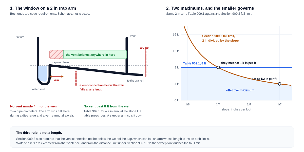
A trap arm has a window, not a ceiling. The vent must be at least two pipe diameters from the trap weir, so it clears the area of full flow in the arm, and no further than the distance in Table 909.1. On a 1-1/2 inch arm that window runs from 3 inches to 6 feet.
The upper end of that window is where most of the confusion lives. Table 909.1 is the right upper limit at the slope shown in the table, and it stops describing your limit as soon as the slope changes, because Section 909.2 caps the total fall at one pipe diameter and that cap tightens as the slope steepens. At half an inch per foot a 2 inch trap arm reaches its limit at 4 feet against a table figure of 8, and nothing on the table announces it.
Underneath both numbers sits the rule they exist to serve: the vent connection must not be below the weir of the trap. A trade article on this subject puts it plainly, that the weir statement always trumps a length taken from a table, because it is the actual condition that prevents a siphon forming. A length inside both limits with the vent below the weir is not a compliant trap arm.
Water closets are excepted, and from two different things in two different sentences. Section 909.1 removes the distance limit. Section 909.2 removes the weir restriction. Neither removes the one diameter fall limit, which is why this calculator still reports the fall for a water closet.
What to Look at First
Read the window before the maximum. A trap arm is bounded at both ends: the vent may not sit within two pipe diameters of the trap weir, and it may not sit further away than the smaller of two different maximums. Almost every reference covers the upper end and stops.
Then check which rule produced the maximum. Table 909.1 is correct at the slope its own slope column prescribes, and Section 909.2 caps the total fall at one pipe diameter, which tightens as the slope steepens. Above a quarter inch per foot the fall rule governs and the table figure becomes unreachable.
Then read the weir line. That rule is geometry rather than distance, it can fail an arm whose length sits comfortably inside both limits, and a green length above a failed weir is not a result this page will show you.
How to Use This Calculator
Enter the trap arm size, meaning the pipe between the trap weir and the vent fitting. Not the branch it discharges into. This page is the opposite of vent sizing, where the downstream drain size is what matters.
Choose the fixture category. A water closet, another self siphoning fixture, or any other fixture. The first two have no distance limit, and the classification changes what the result can tell you.
Enter the planned slope if you have it. Without it the fall limit cannot be computed and the page will say so rather than presenting the table figure as a complete answer.
Enter the actual developed length if you want a verdict rather than a limit. Measure along the path of the pipe from the trap weir to the vent fitting, not as a straight line and not from the trap outlet.
Say whether the vent connection sits at or above the trap weir. Unanswered, the geometry is reported as not fully checked, because that rule can fail a design whose length is comfortably inside both limits.
Read the window, the two limits, and which one governs. The result shows the arithmetic for both rather than a bare figure, so the number can be checked rather than trusted, and it states how complete the check was.
Only the trap arm size and the fixture category are required. The slope, the developed length and the weir answer are all optional and none of them block Calculate; each one left blank is reported as not evaluated, which is not the same as compliant.
Inputs & Outputs
Inputs
Outputs
Trap Arm Length Formula
Three limits bound a trap arm and each one comes from a different rule. The smallest maximum governs, the minimum is a floor rather than a guideline, and the weir requirement is not a length at all.
Minimum distance from the trap weir
minimum_in = 2 * diameter_in
A vent shall not be installed within two pipe diameters of the trap weir. On a 2 inch arm that is 4 inches, and on a 1-1/2 inch arm it is 3 inches. Closer than that the vent opens into the area of full flow in the arm and cannot draw air.
Table limit, Table 909.1
1-1/4 gives 5 ft, 1-1/2 gives 6 ft, 2 gives 8 ft
3 gives 12 ft, 4 gives 16 ft
The maximum developed length printed in the table, alongside a slope column that prescribes the slope those distances assume. The five rows are the whole table.
Fall limit, Section 909.2
fall_limit_ft = diameter_in / slope_in_per_ft
The length at which the total fall reaches one pipe diameter. This one tightens as the slope steepens, and it is the limit the table never mentions.
Effective maximum
effective = the smaller of table and fall limits
Both rules apply at once and the smaller of them governs. At a quarter inch per foot they coincide on every listed size.
Total fall over a run
fall_in = length_ft * slope_in_per_ft
Compared against the one pipe diameter ceiling, which is 2 inches on a 2 inch arm and 3 inches on a 3 inch arm.
At a quarter inch per foot
fall_limit_ft = diameter_in * 4
Which reproduces every distance in Table 909.1: 5 feet on 1-1/4 inch, 6 on 1-1/2, 8 on 2, 12 on 3 and 16 on 4.
Unit conversions
1 inch equals 25.4 mm, 1 foot equals 0.3048 m, and 1 inch per foot equals 83.3 mm per metre. So a quarter inch per foot is 20.8 mm per metre, an eighth is 10.4 and a half is 41.7.
The remaining rules are conditions rather than equations: the vent connection must not be below the trap weir, water closets are excepted from the distance limit and from the weir rule in two separate sentences, and the entered slope must still meet the minimum for drainage piping of that size.
Trap Arm Length Chart
Table 909.1 gives the maximum developed length from the trap weir to the vent fitting, by trap arm size.
A 1-1/4 inch arm allows 5 feet, which is 1.52 metres. A 1-1/2 inch arm allows 6 feet, 1.83 metres. A 2 inch arm allows 8 feet, 2.44 metres. A 3 inch arm allows 12 feet, 3.66 metres. A 4 inch arm allows 16 feet, 4.88 metres.
| Trap arm size | Maximum length | Metric size | Metric length |
|---|---|---|---|
| 1-1/4 in | 5 ft | 31.8 mm | 1.52 m |
| 1-1/2 in | 6 ft | 38.1 mm | 1.83 m |
| 2 in | 8 ft | 50.8 mm | 2.44 m |
| 3 in | 12 ft | 76.2 mm | 3.66 m |
| 4 in | 16 ft | 101.6 mm | 4.88 m |
The table has five rows and no others. A 2-1/2 inch or 6 inch trap arm is not in it, and interpolating between rows is not a code answer.
Two things about the table are easy to miss.
It carries a slope column as well as a distance column. The distances are the maximum at the slope the table prescribes, not at any slope you choose. A trade article on fixture drain lengths names this as the thing readers most often skip: they see a quarter inch per foot in the slope column and assume it is repeating the minimum drainage slope for that pipe size, which is a different requirement from a different table.
And the distances are maximums rather than a compliance check. A length inside the table can still fail on the fall limit if the arm is steeper than the table slope, on the minimum distance if the vent sits closer than two pipe diameters, or on the weir rule regardless of any length. The table answers one question out of four.
The 4 inch row is worth a note. Some published summaries give 20 feet rather than 16. The figure used here is 16 feet, confirmed against two independent sources and consistent with the fall limit at the table slope.
Minimum Trap Arm Distance
Almost every discussion of trap arms covers the maximum and stops. There is a minimum as well, and it catches people fitting a vent tight to the trap to save space.
A vent shall not be installed within two pipe diameters of the trap weir. The Uniform Plumbing Code states the same requirement as not less than two times the diameter of the trap arm.
| Trap arm size | Minimum distance | Metric |
|---|---|---|
| 1-1/4 in | 2.5 in | 63.5 mm |
| 1-1/2 in | 3 in | 76.2 mm |
| 2 in | 4 in | 101.6 mm |
| 3 in | 6 in | 152.4 mm |
| 4 in | 8 in | 203.2 mm |
The reason is hydraulic rather than arbitrary. Immediately downstream of the trap weir the arm runs full during a discharge, and a vent opening into that region is submerged at exactly the moment it is needed. Two pipe diameters moves the vent connection past the area of full flow so it can draw air while the fixture is draining, which is the whole point of a protecting vent. Published guidance describing the research behind these rules makes the same point: the two diameter distance moves the inner edge of the vent away from the area of full flow in the trap arm and allows the vent to function properly.
So a trap arm has a window. On a 1-1/2 inch arm the vent connection belongs somewhere between 3 inches and 6 feet from the trap weir, and both ends are requirements. A vent at 2 inches fails as surely as a vent at 7 feet, and it fails for the opposite reason.
The One Diameter Fall Rule and Slope
Section 909.2 sets a limit that has nothing to do with distance: the total fall in a fixture drain resulting from pipe slope shall not exceed one pipe diameter.
On a 2 inch trap arm that is 2 inches of drop. On a 3 inch arm, 3 inches. The fall over any run is simply the length multiplied by the slope, so the length at which the arm reaches one diameter of fall is the diameter divided by the slope.
That produces a second maximum, and it moves with the slope while the table figure does not. Both limits apply at once and the smaller of them governs.
At the table slope of a quarter inch per foot the two coincide on every listed size. A 2 inch arm reaches 2 inches of fall at exactly 8 feet, which is the table figure. That is why the two rules read as though one repeats the other, and it is why so many people work with the table alone without ever encountering the second rule.
Change the slope and they part company immediately. At half an inch per foot the same 2 inch arm reaches 2 inches of fall at 4 feet, so the effective maximum is 4 feet against a table figure of 8. The relationship is inverse: double the slope and halve the allowable length. A 3 inch arm drops from 12 feet to 6 feet the same way.
| Slope | 1-1/4 in | 1-1/2 in | 2 in | 3 in | 4 in |
|---|---|---|---|---|---|
| 1/8 in per ft | 5 ft | 6 ft | 8 ft | 12 ft | 16 ft |
| 1/4 in per ft | 5 ft | 6 ft | 8 ft | 12 ft | 16 ft |
| 3/8 in per ft | 3.33 ft | 4 ft | 5.33 ft | 8 ft | 10.67 ft |
| 1/2 in per ft | 2.5 ft | 3 ft | 4 ft | 6 ft | 8 ft |
The first two rows are the table figures, because below and at the table slope the table governs. The last two are the fall limit, because above the table slope the fall rule governs and the table figure becomes unreachable.
The other direction does not help. At an eighth of an inch per foot a 2 inch arm would reach one diameter of fall at 16 feet, and the table still caps it at 8. A flatter arm never buys length, because the table governs below the table slope. On piping of 2-1/2 inches and smaller, an eighth of an inch per foot is also below the minimum slope for drainage piping of that size, so the arm would not be a permitted drain at all. That minimum comes from the drainage slope requirements rather than from Section 909, and this calculator reports it as a cross reference for that reason.
The practical consequence is a quiet failure mode. A plumber slopes an arm generously because it drains better, measures against the table, passes, and has installed a trap arm that can siphon its seal. The table gave the wrong answer because it was asked a question outside its own conditions.
The research behind the rules bounds the slope from both sides. Work at the National Bureau of Standards concluded that the slope of a fixture drain should be confined between a quarter and half an inch per foot, which is exactly the range over which these two limits diverge.
Trap Weir to Vent Fitting Measurement
The developed length runs from the trap weir to the vent fitting. Where the tape starts decides whether an arm passes, and it is the single most common way a compliant drawing becomes a non compliant installation.
The trap weir is the point at the bottom of the trap arm pipe where it connects to the trap. It is the top of the water seal, the level over which water spills into the arm. It sits inside the trap rather than at either of its ends, which is why field measurements so often start at the trap outlet instead: the outlet is where a tape can actually be hooked.
That error always reads in the optimistic direction. The outlet is closer to the vent than the weir, so the measured length is short, and a short measurement turns a failing arm into a passing one on paper. Because the fall calculation uses the same length, the error moves both limits the same way at once.
Three other starting points are also wrong and all of them are used. Not the fixture outlet, which is upstream of the trap entirely. Not the wall or the fixture centre line, which are convenient on a drawing and have no relationship to the trap. And not a straight line across a plan, because developed length follows the path of the pipe, so every offset and fitting adds to it.
There is a field method for checking the related weir rule that does not need a tape at all. Measure from a level floor to the bottom of the drain at the trap connection, where the trap weir sits, then measure to the top of the pipe at the vent connection, roughly accounting for the pipe wall. If the second figure is lower than the first, the vent connection is below the weir and the arm fails regardless of its length.
This calculator states the start point on every result rather than assuming it is understood, because a correct calculation on a wrong measurement is worse than no calculation.
Water Closet Trap Arm Exception
Water closets are excepted, and the word exempt does more damage here than almost anywhere else in the vent chapter, because there are two exceptions in two separate sentences and a third rule that neither of them touches.
The first exception is in Section 909.1. The developed length of the fixture drain from the trap weir to the vent fitting for self siphoning fixtures, such as water closets, shall not be limited. That removes the Table 909.1 distance entirely. A water closet trap arm has no maximum length under this section.
The second is inside Section 909.2. That sentence requires the vent connection not to be below the weir of the trap, except for water closets. So a water closet may have its vent connection below the weir, which no other fixture may.
What neither exception touches is the first half of Section 909.2, the one diameter fall limit. That clause applies to a fixture drain generally, and the exception written into the sentence is attached to the weir requirement rather than to the fall requirement.
The reason for the exceptions is in the phrase self siphoning. A water closet siphons its own trap by design, every flush, and then refills the seal from the bowl. Self siphonage is the failure mode the trap arm rules exist to prevent, and on a fixture that does it deliberately and recovers from it, the distance and weir protections lose their purpose.
The practical consequence for this calculator is that a water closet returns no distance verdict, no weir failure, and still returns the fall figure. That is not an oversight. A page reporting a water closet as simply exempt has merged two rules into one and dropped a third.
The Section 909.1 exception is written for self siphoning fixtures generally, with water closets given as the example rather than as the only case. Where a fixture other than a water closet is claimed as self siphoning, that classification is worth confirming with the code and the authority having jurisdiction rather than assumed, and this calculator says so.
Trap Arm Length Versus Vent Pipe Sizing
Two questions get asked about the same vent and they have different answers from different tables. Mixing them is common enough to be worth stating plainly.
Trap arm length is a distance question. How far may the vent be from the trap? The answer comes from Table 909.1 and Section 909.2, it depends on the trap arm size and the slope, and it is what this page computes.
Vent pipe sizing is a diameter question. How large must the vent be? The answer comes from Section 906, it depends on the size of the drain the vent serves, and it has its own page. The two are independent: a correctly sized vent at the wrong distance fails, and a correctly placed vent of the wrong diameter fails.
The inputs even run in opposite directions, which is where the confusion starts. Vent sizing takes the drain that continues downstream of the vent connection, at half its diameter. Trap arm length takes the pipe between the trap weir and the vent fitting, which is upstream of that connection. Feed the branch size into this page and the answer will be too generous; feed the trap arm size into the vent sizing page and the vent will be too small.
Two more pages sit nearby and answer different questions again. Wet vent sizing decides whether a group may be wet vented at all and what diameter that wet vent takes, and it states on its own results that Table 909.1 still governs the trap distances within it. Drain pipe slope gives the fall over a run for drainage piping generally, without the one diameter ceiling, the two diameter minimum or the weir rule that make a trap arm a special case.
Table 909.1 also governs the connection distance within a combination waste and vent system, where the combination pipe is considered the vent for the fixture. This page reports that distance where it applies and does not determine whether the combination arrangement itself is permitted.
What Is a Trap Arm
The trap arm is the portion of a fixture drain between the trap weir and the vent that protects it. It is a short length of pipe with an unusually specific job: it has to carry the discharge away and, at the same time, stay open enough that air can reach the trap and stop the water seal being pulled out.
The trap weir is the point at the bottom of the trap arm pipe where it connects to the trap. It is the top of the water seal, the level over which water spills into the arm, and it sits inside the trap rather than at either end of it.
What can go wrong is self siphonage. A slug of water leaving a fixture fills the arm, and if the vent is too far away, or the arm has fallen too far, the moving water acts as a siphon and drags the trap seal along with it. The seal is gone and the drain becomes an open path between the sewer and the room.
The research behind the limits is old and specific. Work at the National Bureau of Standards in the 1920s and 1950s set out to find the maximum length of a fixture drain without self siphonage, and concluded that the slope should be confined between a quarter and half an inch per foot and that the outlet end of the fixture drain should not extend below the weir of the trap. Those two findings are what the modern rules encode: a distance table built at the table slope, a fall limit of one pipe diameter, and a plain requirement that the vent connection stay above the weir.
There is a lower bound too, from the same body of work. A vent placed within two pipe diameters of the trap weir sits in the area of full flow in the arm, where it cannot draw air, so the code sets that as a minimum.
Key Facts
- Table 909.1 gives the maximum developed length from the trap weir to the vent fitting: 5 feet on a 1-1/4 inch arm, 6 feet on 1-1/2 inch, 8 feet on 2 inch, 12 feet on 3 inch and 16 feet on 4 inch.
- In metric those are 1.52, 1.83, 2.44, 3.66 and 4.88 metres, on arms of 31.8, 38.1, 50.8, 76.2 and 101.6 mm.
- Table 909.1 carries a slope column as well as a distance column, and the slope it prescribes is commonly mistaken for a repetition of the minimum drainage slope.
- A vent shall not be installed within two pipe diameters of the trap weir, which gives a minimum of 2.5 inches on a 1-1/4 inch arm, 3 inches on 1-1/2 inch, 4 inches on 2 inch, 6 inches on 3 inch and 8 inches on 4 inch.
- Section 909.2 caps the total fall in a fixture drain at one pipe diameter, and separately requires that the vent connection not be below the weir of the trap.
- Both the table distance and the fall limit apply at once, and the smaller of them governs.
- At a quarter inch per foot the two coincide on every listed size, because one diameter of fall arrives at four feet per inch of diameter: 1.25 inches at 5 feet, 1.5 at 6, 2 at 8, 3 at 12 and 4 at 16.
- Above a quarter inch per foot the fall limit governs and the table figure becomes unreachable. At half an inch per foot a 2 inch arm is limited to 4 feet rather than 8, and a 3 inch arm to 6 feet rather than 12.
- The relationship is inverse: double the slope and halve the allowable length.
- Below a quarter inch per foot the table governs, so a flatter arm never buys length. On a 3 inch arm at an eighth of an inch per foot the fall rule would allow 24 feet and the table still caps it at 12.
- Minimum drainage slope is a quarter inch per foot for piping of 2-1/2 inches and smaller, and an eighth of an inch per foot for 3 to 6 inch piping. Those come from the drainage slope requirements rather than from Section 909.
- National Bureau of Standards research concluded that the slope of a fixture drain should be confined between a quarter and half an inch per foot, and that the outlet end should not extend below the weir of the trap.
- Section 909.1 excepts self siphoning fixtures, such as water closets, from the developed length limit.
- Section 909.2 separately excepts water closets from the requirement that the vent connection not be below the weir. Neither exception removes the one diameter fall limit.
- The developed length is measured along the path of the pipe from the trap weir to the vent fitting, not as a straight line and not from the trap outlet.
- Table 909.1 also governs the connection distance in combination waste and vent systems, where the combination pipe is considered the vent for the fixture.
- The Uniform Plumbing Code sets its own trap arm distances and carries the same two diameter minimum as not less than two times the diameter of the trap arm.
Applications
- A plumber roughing in a lavatory checks how far the vent can sit from the trap before the arm has to be re-routed, and finds the answer depends on the slope they were planning to use.
- A designer who sloped an arm generously for drainage discovers that the extra slope has halved the allowable distance, and that the table they checked against never mentioned it.
- A contractor fitting a vent close to the trap to save space finds there is a minimum as well as a maximum, and that two pipe diameters is the floor.
- A remodeler moves a wall by a few inches and finds the arm now over the limit, because the measurement runs from the trap weir rather than the trap outlet and the margin was smaller than the drawing suggested.
- An inspector checking a rough-in measures from the trap weir rather than the trap outlet, and finds an arm that passed on the drawing does not pass on site.
- A designer working a floor drain on a long run checks whether Table 909.1 permits the distance at all, before deciding whether a different venting method is needed.
- A plans reviewer checks that a submitted trap arm was tested against both the table and the fall limit rather than the table alone.
Example Calculations
Example 1. The window, on a common fixture
Given: a lavatory on a 1-1/2 inch trap arm.
The minimum distance is two pipe diameters, which is 3 inches or 76.2 mm. The maximum from Table 909.1 is 6 feet, which is 1.83 m.
Result: the vent connection has to sit somewhere between 3 inches and 6 feet from the trap weir. Both ends are code requirements. A vent fitted tight to the trap sits in the area of full flow in the arm and cannot draw air, which is the reason for the lower bound.
Example 2. The two limits agree, and then they do not
Given: a 2 inch trap arm, first at a quarter inch per foot and then at half an inch per foot.
At a quarter inch per foot the table allows 8 feet. The fall limit is the diameter divided by the slope: 2 inches divided by 0.25 inches per foot, which is 8 feet. The two agree exactly and the effective maximum is 8 feet.
At half an inch per foot the table still says 8 feet. The fall limit becomes 2 divided by 0.5, which is 4 feet. The effective maximum is 4 feet, and the fall rule governs.
Result: the same pipe, the same table, and half the allowable distance, because the slope changed. Table 909.1 gave the right answer in the first case and the wrong one in the second, and nothing on its face says which case you are in.
Example 3. The table is the fall rule at one slope
Given: each of the five table sizes, checked against the fall limit at a quarter inch per foot.
A 1-1/4 inch arm reaches 1.25 inches of fall at 5 feet, and the table says 5. A 1-1/2 inch arm reaches 1.5 inches at 6 feet, table 6. A 2 inch arm reaches 2 inches at 8 feet, table 8. A 3 inch arm reaches 3 inches at 12 feet, table 12. A 4 inch arm reaches 4 inches at 16 feet, table 16.
Result: every listed row matches. That is why the two rules read as though one repeats the other, and it is why they part company the moment the slope moves off the table slope. The code does not state that the table was produced this way, and this page does not claim it was. What the arithmetic shows is that they coincide there and only there.
Example 4. A flatter arm does not buy length
Given: a 3 inch trap arm at an eighth of an inch per foot, which is the minimum drainage slope permitted at that size.
The fall limit is 3 divided by 0.125, which is 24 feet. The table limit is 12 feet. The effective maximum is 12 feet and the table governs.
Result: halving the slope did not double the allowance, because the table caps it regardless. The same is true at every size, so a designer tempted to flatten an arm to reach a distant vent gains nothing.
Example 5. Over the limit, and the useful part is why
Given: a 2 inch trap arm at half an inch per foot with a developed length of 6 feet.
The effective maximum is 4 feet, so the arm is over by 2 feet. The total fall is 6 times 0.5, which is 3 inches, against a one diameter ceiling of 2 inches.
Result: over the limit, with the fall rule governing. The actionable part is that Table 909.1 would have allowed 8 feet and the slope is what removed it. The remedies follow from that: reduce the slope to the table slope where the drainage minimum allows, move the vent connection closer to the trap, or use a venting method that does not depend on this distance.
Example 6. Inside both limits and still not compliant
Given: a lavatory on a 1-1/2 inch arm at a quarter inch per foot, developed length 4 feet, with the vent connection below the trap weir.
The effective maximum is 6 feet, so 4 feet is comfortably inside it. The total fall is 1 inch against a 1.5 inch ceiling.
Result: not compliant. The vent connection must not be below the weir of the trap, and that requirement is not a length. A trade article on fixture drain lengths makes the point directly, that the weir statement always trumps a length taken from a table because it is the condition that actually prevents a siphon forming. This calculator therefore fails the result rather than showing a green length with a note beside it.
Example 7. A water closet, and what is actually excepted
Given: a water closet on a 3 inch arm at a quarter inch per foot, developed length 20 feet, with the vent connection below the weir.
Section 909.1 excepts self siphoning fixtures from the developed length limit, so 20 feet is not a distance failure. Section 909.2 excepts water closets from the weir requirement, so the connection below the weir is not a geometry failure either.
The total fall over 20 feet at a quarter inch per foot is 5 inches, against a one diameter ceiling of 3 inches.
Result: two exceptions applied and one rule still standing. Neither exception touches the one diameter fall limit, whose exception clause is written only against the weir requirement. A calculator that reports a water closet as simply exempt has merged two rules into one and dropped a third.
Example 8. Measured from the wrong place
Given: a 2 inch trap arm where the run measures 7 feet 6 inches from the trap outlet to the vent fitting, and 8 feet 2 inches from the trap weir.
Measured from the outlet the arm is inside the 8 foot table limit. Measured from the weir it is not.
Result: the same installation passes or fails depending on where the tape started. The code measures from the trap weir, which is inside the trap at the top of the water seal, not from the outlet where it is convenient to hook a tape. Because the fall calculation uses the same length, the error moves both limits in the same optimistic direction at once.
Example 9. A slope that is loose on one rule and short on another
Given: a 2 inch trap arm at an eighth of an inch per foot.
The fall limit is 2 divided by 0.125, which is 16 feet, so the fall rule is slack. The table still caps the distance at 8 feet, so the effective maximum is 8 feet.
But an eighth of an inch per foot is below the minimum drainage slope for piping of 2-1/2 inches and smaller, which is a quarter inch per foot.
Result: the arm satisfies both trap arm limits and is not a permitted drain, because the slope is below the drainage minimum for that size. That minimum comes from the drainage slope requirements rather than from Section 909, so this calculator reports it as a cross reference rather than as a Section 909 failure. A trap arm can be right on every rule this page owns and still be wrong.
Example 10. A table only result is not a pass
Given: a 2 inch trap arm with a developed length of 7 feet, and no slope entered.
Seven feet is inside the 8 foot table limit, so the arm passes the table check.
The fall limit cannot be computed without a slope, so the second of the two maximums was never tested. The weir position was not answered either.
Result: within the table limit only. The calculator says so in those words rather than returning a compliant verdict, because two of the four checks did not run. Table 909.1 answers one question, and a length inside it is the beginning of the check rather than the end of it.
Standards & References
- 2024 International Plumbing Code, Chapter 9, Vents Contains Section 909 on fixture vents, Section 909.1 with Table 909.1 for the maximum distance of a fixture trap from its vent, and Section 909.2 for the one diameter fall limit, the trap weir requirement and the two pipe diameter minimum.
- 2024 International Plumbing Code, Section 909.1, Distance of Trap From Vent The section that carries Table 909.1 and the exception removing the developed length limit for self siphoning fixtures.
- UpCodes, Section 909.1, Distance of Trap From Vent The section text across several code editions and jurisdictions, for free reading and for checking what a local amendment has changed.
- UpCodes, Fixture Vents Carries the Section 909.2 text including the one diameter fall limit, the trap weir requirement and the rule that a vent shall not be installed within two pipe diameters of the trap weir.
- Journal of Light Construction, Maximum Length for Fixture Drains A trade article on why the trap weir requirement matters more than the table figure, on the slope column being mistaken for the drainage minimum, and on how to check the weir in the field by measuring to the bottom of the drain at the trap connection and to the top of the pipe at the vent connection.
- International Association of Plumbing and Mechanical Officials, Uniform Codes Spotlight Describes the National Bureau of Standards research behind the trap arm rules, including the finding that slope should be confined between a quarter and half an inch per foot and that the outlet end of the fixture drain should not extend below the weir of the trap, and explains why two pipe diameters is the minimum distance.
- International Code Council, Building Safety Journal: methods of venting plumbing fixtures and traps Places Table 909.1 within the individual venting method in the 2021 International Plumbing Code and connects it to the vent sizing rules.
Units
Diameters are entered and reported in inches with millimetres alongside. Convert with 1 inch equal to 25.4 mm, so the five trap arm sizes are 31.8, 38.1, 50.8, 76.2 and 101.6 mm.
| Trap arm size | Metric | Table maximum | Metric | Two diameter minimum | Metric |
|---|---|---|---|---|---|
| 1-1/4 in | 31.8 mm | 5 ft | 1.52 m | 2.5 in | 63.5 mm |
| 1-1/2 in | 38.1 mm | 6 ft | 1.83 m | 3 in | 76.2 mm |
| 2 in | 50.8 mm | 8 ft | 2.44 m | 4 in | 101.6 mm |
| 3 in | 76.2 mm | 12 ft | 3.66 m | 6 in | 152.4 mm |
| 4 in | 101.6 mm | 16 ft | 4.88 m | 8 in | 203.2 mm |
Why nominal sizes stay in inches
Nominal pipe sizes stay in inches in both unit systems, because that is how drainage pipe is specified, ordered and inspected wherever this code applies. A 2 inch trap arm is a 2 inch trap arm whichever units the rest of the calculation is in, and the code itself prints the metric figures as conversions beside the inch sizes.
Length
Length is entered in feet or metres, with 1 foot equal to 0.3048 m, so the five table distances are 1.52, 1.83, 2.44, 3.66 and 4.88 metres. The two diameter minimum is reported in inches and millimetres rather than in feet, because on every size it is under a foot.
Slope
Slope is entered in inches per foot or millimetres per metre. The code prints the conversion as 1 inch per foot equals 83.3 mm per metre, so a quarter inch per foot is 20.8 mm per metre, an eighth is 10.4 mm per metre and half an inch is 41.7 mm per metre.
Fall
Fall is reported in inches and millimetres, against a ceiling of one pipe diameter. On a 2 inch arm that ceiling is 2 inches or 50.8 mm.
Which switch wins
The internal unit selector governs the fields, labels, math, on-screen result and any exported result, and it takes priority over the site header switch. Switching converts the values you entered rather than reinterpreting them, so 6 ft becomes 1.83 m and returns to exactly 6 ft when you switch back.
Limitations
- This calculator covers the distance between a trap weir and its vent under Section 909. It does not size the vent, which is Section 906 and a different calculation, and it does not size the drain.
- It models the five trap arm sizes listed in Table 909.1: 1-1/4, 1-1/2, 2, 3 and 4 inch. A size outside that list returns a state rather than an interpolated figure, because the table is a list of sizes rather than a curve.
- Without a slope the fall limit cannot be computed. The page reports the table figure and says the fall rule was not evaluated, and a length inside the table is reported as within the table limit only rather than as a full pass.
- The weir check depends on an answer from the user. Unanswered, the geometry is reported as not fully checked, and that is not the same as compliant.
- The minimum drainage slope figures come from the drainage slope requirements rather than from Section 909, and are reported as a cross reference.
- That the table distances match the one diameter fall limit at a quarter inch per foot on every listed row is an arithmetic observation, not a statement the code makes about how the table was produced.
- The National Bureau of Standards findings are reported through a secondary account of that research rather than from the original bulletins.
- This page does not design island fixture venting, combination waste and vent systems, or any arrangement belonging to wet, circuit or common venting. It can report the Table 909.1 distance that applies within a combination waste and vent system, and it does not determine whether the combination arrangement itself is permitted.
- The Uniform Plumbing Code sets its own trap arm distances and does not match Table 909.1 row for row. An answer from this page applies to IPC jurisdictions, and local amendments change both the values and the section numbering.
Common Mistakes to Avoid
- Reading the table and stopping. Table 909.1 is correct at the slope its own slope column prescribes. Change the slope and the fall limit in Section 909.2 becomes the binding rule, and the table says nothing about it.
- Assuming the slope column is repeating the drainage minimum. It is not. It is the slope the table distances assume, and a trade article on this subject names that assumption as the thing readers most often skip.
- Calling a table only result compliant. If the slope or the weir position is unknown, the calculator can report the table distance and it cannot confirm the trap arm. Table 909.1 is one of four checks, and a length inside it is where the check starts.
- Sloping the arm more steeply to help it drain. The steeper the arm, the sooner it reaches one pipe diameter of fall, so the allowable distance shrinks in proportion. At half an inch per foot a 2 inch arm is limited to 4 feet rather than 8.
- Flattening the arm to reach a distant vent. It does not work. Below the table slope the table governs and the distance is unchanged, and on piping of 2-1/2 inches and smaller a flatter slope is below the drainage minimum anyway.
- Measuring from the trap outlet. The code measures from the trap weir, which is inside the trap at the top of the water seal. The outlet is closer to the vent, so the error always reads in the optimistic direction, and it corrupts the fall calculation at the same time.
- Measuring in a straight line. Developed length follows the path of the pipe, so offsets and fittings add to it.
- Forgetting there is a minimum. A vent shall not be installed within two pipe diameters of the trap weir, because closer than that it sits in the area of full flow in the arm and cannot draw air.
- Treating the weir rule as advice. The vent connection must not be below the weir of the trap, and that requirement can fail an arm whose length is comfortably inside both limits.
- Reading the water closet exception as a blanket exemption. Section 909.1 removes the distance limit and Section 909.2 removes the weir restriction, in two separate sentences. Neither removes the one diameter fall limit.
- Using the downstream branch size. The trap arm size is the pipe between the trap weir and the vent fitting, not the branch it discharges into.
Frequently Asked Questions
How far can a trap be from its vent?
Is there a minimum distance from the trap to the vent?
What is the one pipe diameter rule?
Why does a steeper slope reduce the allowable trap arm length?
Can I use a flatter slope to reach a vent further away?
Where exactly is the trap arm measured from?
Can the vent connect below the trap weir?
Are water closets exempt from trap arm length rules?
Does Table 909.1 already include the slope?
What if I do not know the slope?
What happens if the vent is too close to the trap?
Can a trap arm be too flat?
Does this calculator apply under the UPC?
Frequently Used Together
Engineers often use these calculators in combination for complete project workflows:
Related Calculators
Explore similar calculators that might be useful for your project:
Plumbing Quick Reference — Keep It On Your Phone On Site
A 10-page field reference for catching pressure, velocity, slope, and pump-sizing mistakes before you order pipe, close a wall, or add a booster.
- Velocity limits, fixture pressure minimums, drain slope, and the 80 psi ceiling in one table
- Worked examples that show why a single pressure number gives four different answers
- Keep it on your phone, or print the two field-check pages
Free PDF. Calculators stay free. Unsubscribe anytime.
Calculate
This selector governs every field, label, result and export on this page, and it takes priority over the site header switch. Switching converts the values you entered rather than reinterpreting them, so 6 ft becomes 1.83 m and a quarter inch per foot becomes 20.8 mm per metre. Nominal trap arm sizes stay in inches in both systems with millimetres alongside, because that is how drainage pipe is specified, ordered and inspected wherever this code applies.
The Trap Arm
Use the pipe size of the fixture drain between the trap weir and the vent fitting, not the size of the branch it discharges into. This page is the opposite of vent sizing, where the drain continuing downstream is what matters. Table 909.1 publishes these five sizes and no others, and a 2-1/2 inch or 6 inch arm returns a state rather than an interpolated figure.
Section 909.1 excepts self siphoning fixtures, such as water closets, from the developed length limit, so the category decides whether a maximum distance applies at all. The exception names water closets as the example rather than as the only case, which is why the two are offered separately: choosing the second adds an advisory to confirm the classification with the code and the authority having jurisdiction.
The Slope, the Length and the Weir (none of these block Calculate)
A quarter inch per foot is 20.8 mm per metre, an eighth is 10.4 and a half is 41.7. Without a slope the one pipe diameter fall limit cannot be computed, and the page reports the table figure with the fall rule marked as not evaluated rather than presenting it as a complete answer.
Measured along the path of the pipe rather than as a straight line, starting at the trap weir and ending at the vent fitting. Not from the trap outlet, the fixture outlet, the wall, the centre of the fixture or the start of the branch. Leave it blank to get the limits without a verdict.
The trap weir is inside the trap, at the top of the water seal where water spills into the trap arm. It is not the trap outlet, and a field measurement taken from the outlet is shorter and optimistic. Left unanswered, the geometry is reported as not fully checked, because this rule can fail an arm whose length is inside both limits.