Why Two Systems with the Same Tonnage Behave Differently in Humid Air
Two cooling systems rated at the same tonnage can leave one building comfortable and another clammy, because total capacity says nothing about how that capacity divides between lowering temperature and removing moisture, and the sensible heat ratio is the number that describes the split.
Cooling air does two separate jobs. Sensible cooling lowers the dry-bulb temperature, and the load driving it comes from sun, conduction, lights, equipment, and warm outdoor air. Latent cooling condenses moisture out of the air, and the load driving it comes from people, humid ventilation air, infiltration, and process sources such as cooking or open water. A ton of cooling spent condensing water is a ton not spent lowering temperature. Equipment divides its capacity between the two according to its coil design and operating conditions, and a space divides its load between the two according to climate, occupancy, and ventilation. When those two splits disagree, the space either runs humid or overcools.
The calculator adds the sensible and latent loads to get the total, then divides sensible by total to give the sensible heat ratio, a dimensionless number between zero and one, with the latent fraction as its complement. A high ratio means the load is temperature-driven; a low ratio means moisture removal dominates. The CRAC Unit Sizing article treated a data room as a nearly pure sensible load and warned against matching room-sensible capacity to a unit's total nameplate. This article generalizes that warning: every space has a sensible heat ratio, and every coil has one — the design succeeds when the two match at the actual operating conditions. ASHRAE defines total cooling load as the sum of the sensible and latent components, and the sensible heat ratio as the sensible share of that total.
Calculator Inputs: Sensible Load and Latent Load
The calculator collects two loads and the unit system, then returns the total, the ratio, and the two fractions.
Unit System. Imperial (BTU/hr) or Metric (kW). The structure is identical in both modes; only the load units change, and the ratio itself carries no unit.
Sensible Load [BTU/hr or kW]. The portion of the cooling load that changes air temperature. It comes from a cooling load calculation: envelope conduction, solar gain, internal gains, and the ventilation temperature difference. Typical range for a commercial zone: 12,000 to 300,000 BTU/hr (3.5 to 88 kW).
Latent Load [BTU/hr or kW]. The portion that removes moisture, the output of a latent load calculation. It comes from occupant moisture, ventilation and infiltration humidity, and process sources. Typical range in comfort work: 5 to 45 percent of the total.
Outputs are Total Cooling Load (BTU/hr or kW), Sensible Heat Ratio (dimensionless, 0 to 1), Sensible Fraction (%), and Latent Fraction (%).
Sensible Load + Latent Load → Total Cooling Load → SHR = sensible / total
Both loads must be entered in the same unit, both in BTU/hr or both in kW. The ratio is dimensionless, so the SHR value is identical in either system.
The calculator does not compute the loads; it splits a load already calculated. Sensible and latent components come from an ASHRAE load method, ACCA Manual J, load software, or a measured and estimated component tally.
The calculator does not account for room relative humidity directly, the coil leaving-air condition, apparatus dew point, bypass factor, ventilation-air mixing, infiltration moisture generation, process moisture sources, equipment net sensible and latent capacity at real entering conditions, altitude effects, or part-load and staging behavior. It is a screening load-split indicator.
The Ratio: Sensible Over Total, and Its Latent Complement
The sensible heat ratio is a plain division, the sensible load over the total, and its complement is the latent fraction, so one number describes the entire split.
Q_total = Q_sensible + Q_latent              [BTU/hr or kW]

SHR = Q_sensible / Q_total
    = Q_sensible / (Q_sensible + Q_latent)   [dimensionless, 0 to 1]

Sensible fraction (%) = SHR × 100
Latent fraction (%)   = (1 − SHR) × 100
Q_sensible and Q_latent are both cooling loads in BTU/hr or kW, and both must sit on the same load boundary. Q_total is their sum, in the same unit, and converts to tons at 12,000 BTU/hr or 3.51685 kW per ton. SHR runs from 0.50 to 1.00 in nearly all cooling applications.
Worked, in Imperial:
Q_sensible 24,000 BTU/hr (7.03 kW), Q_latent 8,000 BTU/hr (2.34 kW)
Q_total = 24,000 + 8,000 = 32,000 BTU/hr (9.38 kW, 2.67 tons)
SHR = 24,000 / 32,000 = 0.75
Sensible 75%, latent 25%
Reading the number:
| SHR | What the split means | Where it appears |
|---|---|---|
| 1.00 | All sensible, no moisture removal | A dry process, or a data room approaching it |
| 0.75 | Three quarters temperature, one quarter moisture | Typical comfort cooling |
| 0.50 | Half the capacity spent condensing water | Heavy latent burden |
| Below 0.60 | Moisture removal dominates | Natatorium, commercial kitchen |
The ratio is bounded. Because the total is the sum of the two parts, SHR cannot exceed 1.0 under a normal cooling load, and a value above 1.0 or below 0 indicates an input error or a nonstandard case.
It is also scale-free. The ratio cancels units, so it places a 3-ton residential system and a 300-ton chiller plant on one scale, and two spaces with the same ratio have the same load character regardless of size.
Per ASHRAE Handbook Fundamentals, total cooling load is the sum of the sensible and latent components, and the sensible heat ratio is the sensible share of that total, dimensionless between 0 and 1, with the latent fraction as its complement.
Where Sensible Load Comes From and Where Latent Load Comes From
The two halves of the load come from different physical sources, and knowing which sources feed which side is how an engineer predicts a space's ratio before any equipment is chosen.
Sensible sources, temperature-driven:
- Solar radiation. Sunlight through glazing and onto the envelope, often the largest sensible peak in perimeter spaces.
- Conduction. Heat through walls, roof, floor, and glazing, driven by the outdoor-to-indoor temperature difference, commonly 20 to 30°F (11 to 17°C) at design.
- Internal gains. Lighting, plug loads, equipment, and the sensible portion of occupant heat.
- Ventilation sensible. The temperature difference between outdoor and indoor air acting on the ventilation stream.
Latent sources, moisture-driven:
- Occupants. Respiration and perspiration, roughly 200 to 500 BTU/hr (59 to 147 W) latent per person depending on activity.
- Outdoor air ventilation. Humid outdoor air brought in for indoor air quality, often the dominant latent term in humid climates.
- Infiltration. Uncontrolled envelope leakage carrying outdoor moisture.
- Process moisture. Cooking, dishwashing, laundry, open pools, and wet industrial processes.
- Moisture migration. Vapor diffusion through building materials, usually small but persistent.
The occupant contribution splits both ways. A person emits both, the sensible portion warming the air and the latent portion adding moisture, and at office activity roughly half of a person's total heat output is latent. High occupancy therefore lowers the ratio twice: more people, and more moisture per unit area.
The source list is what lets the ratio be predicted from a space description alone:
| Space | Load character | Ratio |
|---|---|---|
| Sunlit perimeter office, few people | Sensible-dominated | High SHR |
| Packed lecture hall, high ventilation, humid climate | Latent-heavy | Low SHR |
| Data room, no people, minimal outdoor air | Nearly pure sensible | SHR near 1.0 |
Per ASHRAE Handbook Fundamentals and ACCA Manual J, sensible load comes from solar, conduction, internal gains, and the ventilation temperature difference, while latent load comes from occupants, ventilation and infiltration moisture, and process sources. Occupants and outdoor air are the two terms that most often push the ratio down.
Typical SHR Ranges by Application
Applications cluster into recognizable bands, and knowing the band a project falls in sets expectations before the load calculation is finished.
| Application | Typical SHR |
|---|---|
| Dry climates or sensible-heavy spaces | 0.85 to 0.95 |
| Standard comfort cooling | 0.70 to 0.85 |
| Humid climates or high-occupancy spaces | 0.55 to 0.75 |
| Natatoriums, commercial kitchens, process spaces | Below 0.60 |
| Data rooms and equipment spaces | 0.90 to 1.00 |
What moves a project within its band:
| Change in the space | Effect on SHR |
|---|---|
| Higher outdoor air fraction | Lower |
| Higher occupant density | Lower |
| More glazing and solar exposure | Higher |
| Drier climate | Higher |
| Process moisture present | Sharply lower |
The bands are guidelines, not targets. There is no code-mandated SHR, and the correct value is whatever the load calculation produces. The bands are a sanity check: a comfort office computing a ratio of 0.45 signals an error in the latent estimate, or an unusual moisture source worth confirming.
The band matters for equipment because standard packaged and split cooling equipment is designed around SHR 0.70 to 0.80. Applications well below that band need equipment selected for latent capacity, or a separate dehumidification strategy.
Climate is the strongest single predictor. The same office in Phoenix and in Miami has a different ratio at a similar design dry-bulb near 95°F (35°C): the Phoenix ventilation air carries little moisture, the Miami air carries a great deal, at the same ventilation rate.
Per ASHRAE Handbook Fundamentals and HVAC Applications, applications fall into recognizable bands, from below 0.60 for natatoriums and kitchens to 0.85 through 0.95 for dry sensible-heavy spaces, with standard comfort cooling at 0.70 to 0.85. The bands are sanity checks; the load calculation governs.
Space SHR versus Equipment SHR: The Mismatch Behind Humidity Complaints
A space has a sensible heat ratio and a cooling coil has one, and when the equipment's ratio is higher than the space's, the system satisfies the thermostat while leaving moisture behind, which is the most common cause of humidity complaints in otherwise correctly sized buildings.
The two ratios:
| Ratio | What it describes | Where it comes from |
|---|---|---|
| Space SHR | The load's own split | The load calculation |
| Equipment SHR | The coil's split at its rated entering conditions | Manufacturer data |
The mechanism is direct. An equipment SHR higher than the space SHR means too little latent capacity, so indoor humidity rises. The thermostat is satisfied on temperature, the compressor stops, and moisture removal stops with it. The space is cool and damp.
A mismatch on the 32,000 BTU/hr (9.38 kW) total, illustrative:
Space SHR 0.60:           latent required  = 32,000 × 0.40 = 12,800 BTU/hr (3.75 kW)
Equipment rated SHR 0.80: latent delivered = 32,000 × 0.20 =  6,400 BTU/hr (1.88 kW)
Latent shortfall          = 12,800 − 6,400 =  6,400 BTU/hr (1.88 kW)
Half the moisture the space produces goes unremoved. The total capacity is adequate and the humidity control still fails — the split is wrong rather than the size.
The opposite mismatch carries a different penalty. An equipment SHR well below the space SHR means the coil removes more moisture than needed, overcooling the space and sometimes requiring reheat, at an energy cost. It is less common as a complaint and more common as an efficiency loss.
Equipment SHR is not a fixed property. A coil's rated SHR shifts with entering air conditions, airflow, and compressor staging. Lower airflow across the coil lowers it, because the colder surface condenses more; higher airflow raises it, because the warmer surface does more sensible cooling and less condensation. Rated SHR is published at specific conditions, so verify it at the actual design entering state.
Oversizing compounds the problem. An oversized unit short-cycles, and short run times remove little moisture even at an adequate rated ratio, because the coil surface never settles into a steady wet condition. The CRAC Unit Sizing article covered the same cycling penalty on the data-center side.
Per ASHRAE Handbook HVAC Systems and Equipment and ACCA Manual S, match the equipment's rated sensible and latent capacity at the actual entering conditions against the space load split. An equipment ratio above the space ratio leaves a latent shortfall, cool and damp air, even when the total capacity is correct.
The 0.65 Threshold and When Enhanced Dehumidification Is Needed
Below a space sensible heat ratio of roughly 0.65, standard cooling equipment can no longer carry the latent load reliably, and the design needs a dedicated dehumidification strategy rather than a larger unit.
A space SHR below roughly 0.65 is the point at which to plan for enhanced dehumidification. Standard packaged and split equipment centers on SHR 0.70 to 0.80, and below 0.65 the required latent share exceeds what a typical coil delivers.
A bigger unit does not solve it. Increasing total capacity raises sensible and latent together, in the coil's own proportion, so the latent shortfall stays proportionally the same while the added capacity worsens cycling. The fix must change the split, not the size.
Strategies that change the split:
- Lower supply air temperature. A colder coil condenses more, lowering equipment SHR, often paired with reheat to avoid overcooling.
- Reheat. Sensible reheat after a deep-cooling coil, decoupling temperature control from moisture removal, at an energy cost.
- Dedicated outdoor air system. A separate unit conditions the ventilation air to a low dew point, removing the largest latent term before it reaches the space.
- Dedicated dehumidification equipment. Desiccant units or standalone dehumidifiers for process spaces and natatoriums.
- Lower airflow across the coil. Shifts the coil's own ratio down, within the manufacturer's stated limits, typically no lower than 350 cfm per ton (47 L/s per kW).
The logic behind a dedicated outdoor air system is that outdoor air is usually the dominant latent term. Treating it separately at the source lets the space-serving equipment run at a higher ratio, matching the remaining space load instead of fighting the ventilation moisture.
Humidity targets give the context. Comfort practice holds indoor relative humidity inside a moderate band, commonly 30 to 60%, and sustained high humidity risks occupant discomfort, condensation on cool surfaces, and microbial growth.
Per ASHRAE Handbook HVAC Applications and ACCA Manual S, a space ratio below about 0.65 calls for enhanced dehumidification: lower supply air temperature with reheat, a dedicated outdoor air system treating the ventilation air, or dedicated dehumidification equipment. Increasing total capacity does not fix a split problem, and it worsens cycling.
Outdoor Air: The Largest Lever on the Latent Side
In most humid-climate projects the ventilation air carries more moisture than every other latent source combined, so the outdoor air fraction is the single strongest lever on a space's sensible heat ratio.
Ventilation dominates the latent side because outdoor air enters at its own humidity ratio and must be brought to the indoor condition. The latent load scales directly with both the airflow and the humidity-ratio difference:
Imperial: Q_latent (BTU/hr) = 4,840 × cfm × ΔW (lb water per lb dry air)
Metric:   Q_latent (W)      = 3,010 × L/s × ΔW (kg water per kg dry air)
The code driver sits behind that airflow. ASHRAE Standard 62.1 sets minimum outdoor air rates by occupancy category and floor area, so the ventilation rate is not freely adjustable downward; it is a code minimum. Higher-occupancy spaces require more outdoor air, which is why occupancy lowers the ratio twice: directly through occupant moisture, and indirectly through the ventilation it mandates.
Latent load tracks humidity, not temperature. A mild but humid day can carry a large latent load with a small sensible one, and peak latent and peak sensible do not occur at the same hour, so the ratio at the sensible peak differs from the ratio at the latent peak.
The design implication is to check the load split at more than one design condition. A system sized at the sensible peak may face a lower ratio at the humid part-load condition, which is often when humidity complaints appear.
Energy recovery attacks the term at its source. An enthalpy wheel or membrane exchanger transfers moisture between exhaust and intake, cutting the ventilation latent load before it reaches the coil and raising the effective ratio. Total-energy devices commonly recover 50 to 75% of the ventilation enthalpy difference.
Per ASHRAE Standard 62.1 and Handbook Fundamentals, outdoor air is usually the dominant latent term in humid climates, and code sets its minimum rate. Latent load tracks the humidity-ratio difference, so peak latent and peak sensible fall at different hours; check the split at more than one condition.
The Condition Line: How SHR Sets the Supply Air Temperature
On a psychrometric chart the sensible heat ratio appears as the slope of the line connecting the supply air state to the room state, which is how the ratio translates into a required supply air temperature.
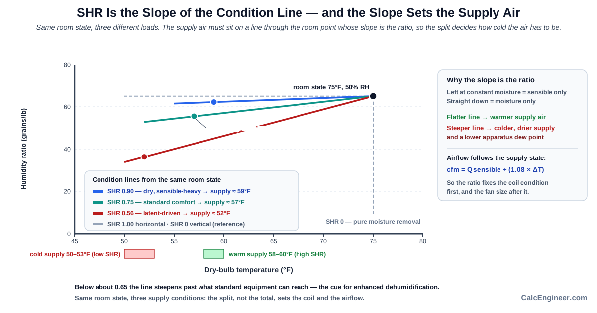
Plot the room design state, dry-bulb and humidity ratio, on the chart. Draw a line through it at the slope corresponding to the ratio, read from the chart protractor. The supply air state must lie on that line, below and to the left of the room state.
Why the slope encodes the ratio:
| Movement on the chart | What it represents | SHR | Line |
|---|---|---|---|
| Left at constant moisture | Pure sensible cooling | 1.0 | Horizontal |
| Down at constant temperature | Pure moisture removal | 0 | Vertical |
| Both at once | A mixed load | Between the two | The ratio sets the angle |
The supply temperature consequence, read for a room at 75°F (24°C) and 50% relative humidity:
| Ratio | Condition line | Supply air for the same room state |
|---|---|---|
| Higher SHR, more sensible | Flatter | Warmer, near 58 to 60°F (14 to 16°C) |
| Lower SHR, more latent | Steeper | Colder and drier, driven toward 50 to 53°F (10 to 12°C) to reach the required supply humidity, pushing the coil toward a lower apparatus dew point |
Airflow follows from the supply state. Once the supply temperature is set, the sensible load and the supply-to-room temperature difference fix the airflow through the sensible heat equation:
Imperial: cfm = Q_sensible (BTU/hr) / (1.08 × ΔT°F)
Metric:   L/s = Q_sensible (W) / (1.21 × ΔT°C)
The ratio therefore influences both the coil condition and the fan sizing.
Where the calculator stops: it gives the ratio. Locating the supply state on the chart, finding the apparatus dew point, and accounting for coil bypass are psychrometric steps beyond the ratio itself.
Per ASHRAE Handbook Fundamentals, Psychrometrics chapter, the sensible heat ratio is the slope of the condition line from the supply state to the room state. A higher ratio flattens the line and permits warmer supply air; a lower ratio steepens it and forces a colder, drier supply state, which then sets the airflow through the sensible heat equation.
Sensible Heat Ratio Is Not the Room Sensible Heat Factor
Several closely related ratios circulate in cooling load work, and the distinction that matters most is between the general sensible heat ratio used here and the room sensible heat factor, which is defined on the room load alone.
The two definitions:
| Ratio | What it is computed on |
|---|---|
| SHR, as used here | Sensible load divided by total load, for whatever load boundary is stated |
| RSHF, the room sensible heat factor | The room load only, excluding ventilation air treated outside the room |
The boundary changes the number. Include the ventilation latent load and the ratio drops; exclude it, as in a dedicated outdoor air design, and the room ratio is higher. The same building yields different numbers depending on which loads sit inside the boundary.
Related ratios in practice:
| Ratio | What it is computed on |
|---|---|
| Grand sensible heat factor | The total coil load, including ventilation air |
| Effective sensible heat factor | The same, adjusted for coil bypass air |
The practical rule is to state the load boundary whenever a ratio is quoted. Comparing a room-only ratio against a coil-total ratio is a category error that makes equipment look better or worse matched than it is.
This calculator's boundary is whatever sensible and latent loads are entered. Take both from the same one: room-only, or coil-total including ventilation, consistently.
Per ASHRAE Handbook Fundamentals, the sensible heat ratio, the room sensible heat factor, the grand sensible heat factor, and the effective sensible heat factor differ by which loads sit inside the boundary. State the boundary when quoting a ratio, and enter both loads from the same one.
The Data Room Case: Why Server Spaces Sit Near One
A data room is the clearest example of a near-unity sensible heat ratio, because servers produce heat without moisture and the spaces admit few people and little outdoor air.
The ratio approaches 1.0 for four reasons. IT equipment converts electrical power to heat with no moisture release, so it is purely sensible. Occupancy is minimal, so occupant latent load is negligible. Outdoor air is limited to small make-up and pressurization quantities. The remaining latent sources are small enough to be a rounding term.
An illustrative split:
Sensible 30,000 BTU/hr (8.79 kW), latent 1,000 BTU/hr (0.29 kW)
Q_total = 30,000 + 1,000 = 31,000 BTU/hr (9.08 kW, 2.58 tons)
SHR = 30,000 / 31,000 = 0.968
The equipment consequence follows. Computer room air conditioning units are built for high ratios, 0.90 to 1.00, maximizing sensible capacity per unit of total capacity. Selecting a comfort-cooling unit rated near 0.75 for a data room commits a quarter of its capacity to dehumidification the space does not need.
That creates a sizing trap. The room needs sensible capacity, but nameplate total capacity includes latent capacity the space will never use, so matching a room's sensible load to a unit's total rating leaves the sensible cooling short, the trap the CRAC Unit Sizing article addressed directly.
Humidity still needs bounding. A near-unity ratio does not mean humidity is ignored: ASHRAE TC 9.9 sets dew-point and relative humidity limits for equipment reliability, and units can fight each other, one humidifying while another dehumidifies, when controls are not coordinated.
Per ASHRAE TC 9.9 and the data-center cluster, server spaces sit at 0.90 to 1.00 because IT heat is purely sensible with minimal occupancy and outdoor air. Equipment is built for that ratio, and matching a room-sensible load to a comfort unit's total rating leaves the sensible cooling short.
Worked Example: 24,000 Sensible and 8,000 Latent at an SHR of 0.75
A commercial space has a completed cooling load calculation: sensible load 24,000 BTU/hr (7.03 kW) and latent load 8,000 BTU/hr (2.34 kW). The question is which equipment split the space needs.
Step 1. Total cooling load.
Q_total = 24,000 + 8,000 = 32,000 BTU/hr (9.38 kW)
Step 2. Convert to tons for equipment context.
32,000 / 12,000 = 2.67 tons
Check in metric: 9.38 / 3.51685 = 2.67 tons, consistent
Step 3. Sensible heat ratio.
SHR = 24,000 / 32,000 = 0.75
Step 4. Fractions.
Sensible fraction = 0.75 × 100 = 75%
Latent fraction   = (1 − 0.75) × 100 = 25%
Step 5. Interpretation. Three quarters of the cooling duty lowers temperature; one quarter condenses moisture. 0.75 sits inside the standard comfort-cooling band of 0.70 to 0.85.
Step 6. Equipment implication. Standard packaged and split equipment centers on SHR 0.70 to 0.80, so a space at 0.75 is well inside that range: conventional equipment can match this split.
Step 7. Verification against rated capacity. Confirm the selected unit's rated sensible and latent capacity at the design entering conditions. A unit of 32,000 BTU/hr total at a rated SHR of 0.75 delivers 24,000 BTU/hr sensible (7.03 kW) and 8,000 BTU/hr latent (2.34 kW), matching the space exactly.
Step 8. What a mismatch would cost. The same 32,000 BTU/hr unit rated at 0.85 delivers 27,200 sensible and 4,800 latent. Against the space requirement of 8,000 BTU/hr latent, that is a 3,200 BTU/hr (0.94 kW) shortfall, and indoor humidity drifts upward while the space holds temperature.
Step 9. Threshold check. 0.75 is comfortably above the 0.65 threshold, so the ratio alone indicates no enhanced dehumidification strategy.
Step 10. Result.
| Output | Value |
|---|---|
| Total cooling load | 32,000 BTU/hr (9.38 kW, 2.67 tons) |
| Sensible heat ratio | 0.75 |
| Sensible fraction | 75% |
| Latent fraction | 25% |
The split falls in the standard comfort-cooling band, conventional equipment suits it, and the rated sensible and latent capacity should still be verified at design entering conditions before selection.
The decision is a conventional 2.5 to 3 ton unit, selected against its published sensible and latent capacity at the design entering wet-bulb rather than against total tonnage alone. The Cooling Load Calculator produces the two components this ratio splits, the Coil Capacity Calculator gives the coil's own split, and the Supply Air Temperature Calculator locates the supply condition the condition line sets.
Metric and Latent-Driven Worked Examples
Step 1. The metric case starts from two loads: sensible 7.0 kW (23,885 BTU/hr) and latent 2.0 kW (6,824 BTU/hr).
Step 2. Total.
Q_total = 7.0 + 2.0 = 9.0 kW (30,709 BTU/hr, 2.56 tons)
Step 3. Ratio.
SHR = 7.0 / 9.0 = 0.778
Sensible 77.8%, latent 22.2%
Step 4. Interpretation. Primarily sensible, with a meaningful latent share, inside the standard comfort band and slightly higher than the Imperial case. The ratio is dimensionless: the same 0.778 whether the loads are entered in kW or BTU/hr.
Step 5. A latent-driven space at the same total load.
Sensible 18,000 BTU/hr (5.28 kW), latent 14,000 BTU/hr (4.10 kW)
Q_total = 18,000 + 14,000 = 32,000 BTU/hr (9.38 kW), identical to the Imperial case
Step 6. Ratio.
SHR = 18,000 / 32,000 = 0.5625, rounded 0.56
Sensible 56%, latent 44%
Step 7. What changed. The same 2.67 tons of total load, but nearly half the duty is now moisture removal, and equipment selection that worked at 0.75 fails here.
Step 8. Threshold check. 0.56 sits below the 0.65 threshold, so enhanced dehumidification is indicated. Options are colder supply air with reheat, a dedicated outdoor air system treating the ventilation moisture, or dedicated dehumidification equipment.
Step 9. The latent gap against standard equipment.
A conventional unit rated at 0.80 on 32,000 BTU/hr delivers 6,400 BTU/hr (1.88 kW) latent.
The space needs 14,000 BTU/hr (4.10 kW).
Shortfall = 14,000 − 6,400 = 7,600 BTU/hr (2.23 kW), more than half the requirement.
Step 10. Result.
| Case | SHR | Equipment conclusion |
|---|---|---|
| Metric 7.0 / 2.0 kW | 0.778 | Standard band, conventional equipment suits |
| Latent-driven 18,000 / 14,000 BTU/hr | 0.56 | Below threshold, needs a dehumidification strategy |
Same total load, opposite equipment conclusions. Tonnage alone decides nothing.
Per ASHRAE practice, the metric case at 7.0 and 2.0 kW gives 0.778, inside the comfort band. A latent-driven space at the identical 32,000 BTU/hr total but an 18,000 and 14,000 split gives 0.56, below the 0.65 threshold, leaving a 7,600 BTU/hr latent shortfall against conventional equipment. The split, not the total, decides the strategy.
Application Boundaries: Apparatus Dew Point, Bypass Factor, Equipment Curves
The calculator covers the load-split ratio from an existing sensible and latent load, application-band screening, and a first-pass equipment-match indication before psychrometric design begins. Several neighboring questions fall outside that scope.
Load Calculation Itself. The calculator splits loads; it does not compute them. The sensible and latent components come from an ASHRAE load method, ACCA Manual J, or load software.
Room Relative Humidity. The ratio does not predict the resulting indoor humidity. That requires the coil leaving condition, the airflow, and a moisture balance on the space.
Apparatus Dew Point and Bypass Factor. The coil's effective surface temperature and the fraction of air passing without contacting that surface govern the actual leaving-air state. Both lie outside a load-split ratio and require psychrometric coil analysis.
Equipment Performance Curves. A coil's rated ratio shifts with entering dry-bulb and wet-bulb, airflow, and staging. Manufacturer performance data at the actual design condition governs selection; a single rated value is one catalog point.
Ventilation Mixing. The calculator does not model outdoor air mixing with return air, nor the resulting coil entering state. That mixing determines whether the ratio should be read on the room boundary or the coil boundary.
Part Load and Cycling. Ratios are computed at a design condition. Part-load operation, compressor staging, and short cycling change the delivered split, often reducing moisture removal below the rated share.
Altitude. Air density at 5,000 ft (1,524 m) runs roughly 15% below sea level, which changes both the sensible and the latent airflow coefficients. The ratio itself is dimensionless, but the loads feeding it must be computed at site density.
Multiple Design Conditions. Peak sensible and peak latent occur at different hours. A single ratio taken at the sensible peak can understate the latent burden at a humid part-load hour.
Humidity Control Proof. A matched ratio does not by itself prove the system will hold humidity in operation. Controls, coil condition, and part-load behavior all participate.
Per ASHRAE Handbook Fundamentals and ACCA Manual S, load-split screening is the calculator's scope. The load calculation, room humidity prediction, apparatus dew point and bypass factor, manufacturer performance curves, ventilation mixing, part-load behavior, altitude, and multi-condition checks require separate psychrometric analysis. A qualified engineer completes the equipment selection.
Open Sensible Heat Ratio Calculator
Sensible heat ratio by load split: adds the sensible and latent cooling loads to give the total, then divides sensible by total for the ratio, reporting the sensible and latent fractions. A high ratio means the load is temperature-driven; a low ratio means moisture removal dominates. Standard comfort cooling falls between 0.70 and 0.85, while a ratio below roughly 0.65 signals the need for enhanced dehumidification. Compare the space ratio against the equipment's rated sensible and latent capacity at design entering conditions. A screening indicator per ASHRAE, not a psychrometric design engine.
Open Sensible Heat Ratio CalculatorStandards and References
- ASHRAE Handbook, Fundamentals (2021), Nonresidential Cooling and Heating Load Calculations chapter. Sensible and latent load components, the definition of total cooling load as their sum, and the load-source taxonomy used in this article.
- ASHRAE Handbook, Fundamentals (2021), Psychrometrics chapter. The condition line and its slope, the sensible heat ratio protractor, apparatus dew point, bypass factor, and the sensible heat equation relating airflow to load.
- ASHRAE Standard 62.1-2022, Ventilation for Acceptable Indoor Air Quality. Minimum outdoor air rates by occupancy category and floor area, the code driver behind the ventilation latent burden.
- ASHRAE Standard 55-2023, Thermal Environmental Conditions for Human Occupancy. Thermal comfort conditions and the humidity context within which a dehumidification strategy is judged.
- ASHRAE Handbook, HVAC Systems and Equipment (2020), Air-Cooling and Dehumidifying Coils chapter. Coil selection, sensible and latent capacity matching, and how rated equipment ratios shift with entering conditions and airflow.
- ASHRAE Handbook, HVAC Applications (2023). Dehumidification strategies, dedicated outdoor air systems, reheat, and design guidance for natatoriums, kitchens, and other latent-dominated spaces.
- ASHRAE TC 9.9, Thermal Guidelines for Data Processing Environments (5th ed, 2021). Data-room temperature and dew-point envelopes, the basis for the near-unity sensible ratio of server spaces.
- ACCA Manual J (8th ed), Residential Load Calculation. Residential sensible and latent load estimation, occupant latent allowances, and infiltration moisture.
- ACCA Manual S, Residential Equipment Selection. Selecting equipment against rated sensible and latent capacity at design conditions rather than against total nominal tonnage.
- Manufacturer coil and DX performance data (expanded ratings tables). Rated sensible and latent capacity as a function of entering dry-bulb and wet-bulb, airflow, and compressor staging; the source for equipment ratio at the actual design point.
FAQ
How do you calculate sensible heat ratio?
Per ASHRAE Handbook Fundamentals: add the sensible and latent cooling loads to get the total, then divide the sensible load by that total. For 24,000 BTU/hr sensible and 8,000 BTU/hr latent, the total is 32,000 BTU/hr (9.38 kW) and the ratio is 0.75, meaning 75% of the duty lowers temperature and 25% removes moisture. The ratio is dimensionless, so kW inputs give the same number.
What is a typical SHR for comfort cooling?
Per ASHRAE practice: standard comfort cooling falls between 0.70 and 0.85. Dry climates and sensible-heavy spaces run 0.85 to 0.95, humid or high-occupancy spaces 0.55 to 0.75, and natatoriums and commercial kitchens below 0.60. These are sanity-check bands rather than code targets; the load calculation produces the governing value.
Why does a correctly sized system still leave the space humid?
Per ACCA Manual S: because total capacity says nothing about the split. If the equipment's rated ratio is higher than the space's, the thermostat is satisfied on temperature while latent capacity falls short. A 32,000 BTU/hr unit rated at 0.85 delivers 4,800 BTU/hr latent against a space needing 8,000 BTU/hr, and humidity drifts up while temperature holds.
What SHR requires enhanced dehumidification?
Per ASHRAE Handbook HVAC Applications: below roughly 0.65. Standard packaged and split equipment centers on 0.70 to 0.80, so a lower space ratio leaves a latent shortfall. The remedies change the split rather than the size: colder supply air with reheat, a dedicated outdoor air system, or dedicated dehumidification equipment.
What lowers a space's SHR the most?
Per ASHRAE Standard 62.1 and Handbook Fundamentals: outdoor air in a humid climate, usually followed by occupant density. Ventilation air must be brought from its own humidity ratio to the indoor condition, and code sets its minimum rate, so high occupancy lowers the ratio twice, through occupant moisture and through the ventilation it mandates.
Can the sensible heat ratio be greater than one?
Per the definition: not for a normal cooling load, because the total is the sum of the sensible and latent parts, which bounds the ratio between 0 and 1. A value outside that range points to an input error or a nonstandard case, such as a load boundary that excludes part of the total.
Is SHR the same as the room sensible heat factor?
Per ASHRAE Handbook Fundamentals: not exactly. The room sensible heat factor is computed on the room load alone, while the general ratio applies to any stated load boundary, including the coil total with ventilation air. State the boundary whenever a ratio is quoted, and take both loads from the same one.
Related Calculators
- CRAC Unit Sizing Calculator: Data-room cooling sizing, where the near-unity sensible ratio makes the sensible-versus-total distinction critical (article).
- Cooling Load Calculator: The load calculation producing the sensible and latent components this ratio splits.
- Latent Heat Load Calculator: The moisture side of the load, the other half of the denominator.
- Coil Capacity Calculator: The coil's own sensible and latent split to match against the space ratio.
- Supply Air Temperature Calculator: The supply condition the ratio's condition line sets.
- Psychrometric Calculator: Full air-state analysis behind the condition line and the apparatus dew point.
- Ventilation Rate Calculator: Outdoor air quantity per ASHRAE Standard 62.1, the dominant latent term.
- HVAC Delta T Calculator: Supply-to-room temperature difference that sets airflow once the ratio fixes the supply state.