Delta T Calculator
On this page
Calculate
Temperature of air or water leaving the equipment (supply side)
Temperature of air or water returning to the equipment (return side)
Volumetric airflow through the duct or air handler (leave 0 to skip heat transfer calculation)
Overview
The Delta T Calculator helps HVAC engineers and technicians determine the temperature difference between supply and return air (or water) in heating and cooling systems. Delta T (ΔT) is one of the most fundamental diagnostic measurements in HVAC — it reveals whether a system is delivering the correct amount of heating or cooling.
By entering the supply temperature and return temperature, this calculator instantly computes the temperature difference. When airflow (CFM) is also provided, it estimates the sensible heat transfer rate in BTU/hr or watts — enabling quick system performance checks in the field.
Accurate Delta T measurement is essential for diagnosing underperforming equipment, verifying proper refrigerant charge, confirming adequate airflow, and validating system commissioning.
How to Use This Calculator
Select system type — choose from Air System, Water System.
Enter supply temperature — in °C or °F.
Enter return temperature — in °C or °F.
For Air System: enter airflow rate (m³/h or CFM). For Water System: enter water flow rate (L/s or GPM).
Click "Calculate" — get Delta T (ΔT), absolute Delta T, and sensible heat transfer rate.
Compare the measured ΔT against the typical range for your system type; if outside, use the diagnostic table to find the likely cause.
Inputs & Outputs
Inputs
Outputs
Formula
Calculator Formulas
Temperature Difference:
ΔT = T_return − T_supply
Sensible Heat Transfer — Air:
Q = ρ × Cp × V̇ × ΔT
Q = 1.2 × 1005 × V̇ × ΔT
Q = 1.08 × CFM × ΔT
Metric: V̇ in m³/s, Q in watts. Imperial: Q in BTU/hr. The constant 1.08 = 0.075 lb/ft³ × 0.24 BTU/lb·°F × 60 min/hr (sea-level standard air).
Sensible Heat Transfer — Water:
Q = ṁ × Cp × ΔT
Q = V̇ × 4186 × ΔT
Q = 500 × GPM × ΔT
Metric: V̇ in L/s, Q in watts. Imperial: Q in BTU/hr. The constant 500 = 8.33 lb/gal × 1.0 BTU/lb·°F × 60 min/hr.
Variable Reference
| Variable | Meaning | Units |
|---|---|---|
| T_supply | Supply air or water temperature | °C / °F |
| T_return | Return air or water temperature | °C / °F |
| ΔT | Temperature difference | °C / °F |
| V̇ | Volumetric flow rate | m³/s or m³/h / CFM or GPM |
| ρ | Air density (standard) | 1.2 kg/m³ |
| Cp | Specific heat (air ≈ 1005 J/kg·K, water ≈ 4186 J/kg·K) | J/kg·K |
| Q | Sensible heat transfer rate | W or BTU/hr |
| 1.08 | Imperial air constant (0.075 lb/ft³ × 0.24 BTU/lb·°F × 60 min/hr) | — |
| 500 | Imperial water constant (8.33 lb/gal × 1 BTU/lb·°F × 60 min/hr) | — |
What is Delta T in HVAC
Delta T (ΔT) is the temperature difference between two measurement points in a heating, ventilation, or air conditioning system. In practice, it most commonly refers to the difference between the supply air temperature (leaving the equipment) and the return air temperature (entering the equipment).
Delta T is one of the most important diagnostic measurements in HVAC. It tells a technician or engineer whether the system is delivering the expected amount of heating or cooling. Combined with airflow or water flow rate, Delta T enables calculation of the sensible heat transfer rate — the actual thermal output of the system.
Why Delta T Matters
Every HVAC system is designed to produce a specific temperature difference at rated conditions. When the measured Delta T deviates from the expected range, it signals a problem:
- Low ΔT in cooling → possible low refrigerant charge, excessive airflow, or dirty coil
- High ΔT in cooling → possible restricted airflow, dirty filter, or frozen evaporator
- Low ΔT in heating → possible undersized equipment, low gas pressure, or airflow too high
- High ΔT in heating → possible restricted airflow or cracked heat exchanger
Regular Delta T checks are a fast, non-invasive way to verify system health without specialized refrigerant gauges or combustion analyzers.
Typical Delta T Ranges
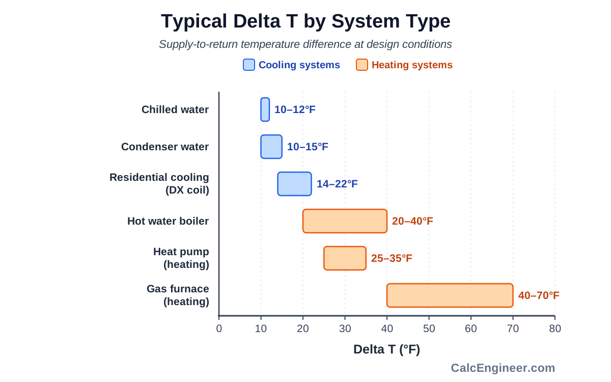
| System Type | Typical ΔT (°F) | Typical ΔT (°C) |
|---|---|---|
| Residential cooling (DX coil) | 14–22 °F | 8–12 °C |
| Gas furnace (heating) | 40–70 °F | 22–39 °C |
| Heat pump (heating mode) | 25–35 °F | 14–19 °C |
| Chilled water (standard) | 10–12 °F | 5.5–6.7 °C |
| Hot water boiler | 20–40 °F | 11–22 °C |
| Condenser water | 10–15 °F | 5.5–8.3 °C |
Diagnosing Problems with Delta T
Cooling Mode Diagnostics
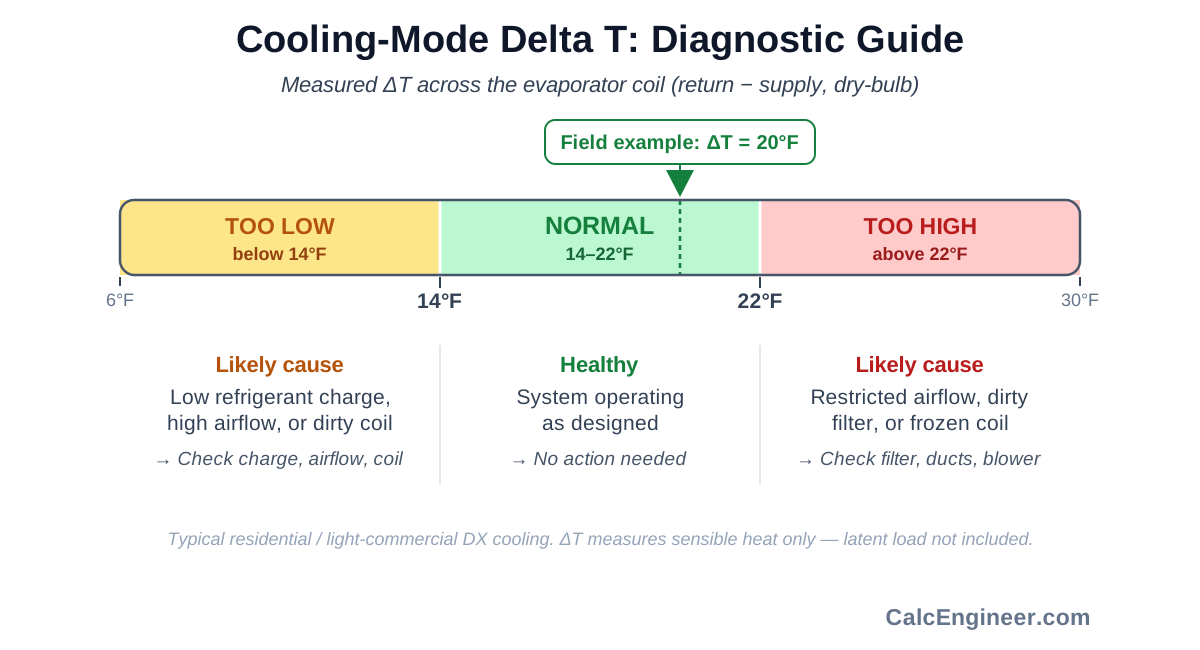
| Measured ΔT | Possible Cause | Action |
|---|---|---|
| Below 14 °F | Low refrigerant, high airflow, dirty coil | Check charge, measure airflow, clean coil |
| 14–22 °F | Normal operation | No action needed |
| Above 22 °F | Low airflow, dirty filter, frozen coil | Check filter, ductwork, blower speed |
Heating Mode Diagnostics
| Measured ΔT | Possible Cause | Action |
|---|---|---|
| Below 25 °F (HP) | Defrost cycle, low charge, auxiliary not staging | Check defrost, charge, thermostat staging |
| 25–35 °F (HP) | Normal heat pump operation | No action needed |
| 40–70 °F (furnace) | Normal gas furnace operation | No action needed |
| Above 70 °F | Low airflow, cracked heat exchanger | Inspect heat exchanger, check airflow |
Practical Field Tips
Wait for steady state — Allow the system to run for at least 15 minutes before measuring Delta T. Startup transients can give misleading readings.
Measure in the right location — For supply temperature, measure at least 6 feet (2 m) downstream of the coil to allow air mixing. For return temperature, measure before the filter.
Use matched sensors — Use two sensors from the same manufacturer and model to minimize measurement error. Even a 1 °F offset between sensors creates significant error on a 20 °F ΔT.
Account for altitude — At elevations above 2,000 ft (600 m), air density is lower. The 1.08 constant must be reduced proportionally. At 5,000 ft, use approximately 0.90 instead of 1.08.
Check both sensible and total capacity — Delta T only measures sensible heat. In humid climates, a significant portion of cooling capacity goes to moisture removal (latent load), which does not appear in the Delta T measurement.
Unit Conversions
| Conversion | Value |
|---|---|
| 1 °C ΔT | 1.8 °F ΔT |
| 1 W | 3.412 BTU/hr |
| 1 kW | 3,412 BTU/hr |
| 1 ton cooling | 12,000 BTU/hr = 3.517 kW |
| 1 CFM | 1.699 m³/h |
| 1 GPM | 0.0631 L/s |
Key Facts
- A typical residential cooling system produces a 14–22 °F (8–12 °C) ΔT across the evaporator coil.
- Gas furnaces typically produce a 40–70 °F (22–39 °C) supply-to-return ΔT.
- Heat pumps in heating mode produce a lower ΔT (25–35 °F) than gas furnaces because they deliver heat at a lower temperature.
- Chilled water systems typically operate at a 10–12 °F (5.5–6.7 °C) ΔT between supply and return.
- The imperial air-side heat transfer constant 1.08 assumes standard air density at sea level (0.075 lb/ft³).
- At higher altitudes, air density decreases — a 5,000 ft elevation reduces the 1.08 factor to approximately 0.92.
Applications
- Diagnosing air conditioning performance — verifying proper refrigerant charge and airflow.
- Commissioning new HVAC systems — confirming design ΔT is achieved.
- Troubleshooting heating systems — checking furnace or heat pump output temperature.
- Chilled water system balancing — verifying coil performance and flow rates.
- Energy auditing — estimating actual heat transfer rates from field measurements.
- Boiler system diagnostics — checking supply and return water temperatures.
Example Calculation
Example 1: Air Conditioning System
Given:
- Supply air temperature = 55 °F (12.8 °C)
- Return air temperature = 75 °F (23.9 °C)
- Airflow = 1,000 CFM (1,699 m³/h)
Calculation:
ΔT = 75 − 55 = 20 °F (11.1 °C)
Q = 1.08 × 1,000 × 20 = 21,600 BTU/hr
Q = 21,600 / 12,000 = 1.8 tons
Result: ΔT = 20 °F — within the normal 14–22 °F cooling range. The system is transferring 21,600 BTU/hr (1.8 tons) of sensible cooling.
Example 2: Chilled Water System
Given:
- Supply water temperature = 44 °F (6.7 °C)
- Return water temperature = 56 °F (13.3 °C)
- Water flow = 24 GPM (1.51 L/s)
Calculation:
ΔT = 56 − 44 = 12 °F (6.7 °C)
Q = 500 × 24 × 12 = 144,000 BTU/hr
Q = 144,000 / 12,000 = 12 tons
Result: ΔT = 12 °F — standard chilled water design ΔT. The system is transferring 144,000 BTU/hr (12 tons).
Standards & References
- ASHRAE Handbook — Fundamentals — psychrometric calculations and heat transfer principles
- ASHRAE Handbook — HVAC Systems and Equipment — coil performance and system diagnostics
- ACCA Manual J — residential load calculations using design ΔT
- ACCA Manual D — duct design based on airflow and temperature requirements
- AHRI Standard 210/240 — rating conditions for unitary air conditioners (95 °F outdoor, 80 °F / 67 °F wb indoor)
Limitations
- This calculator estimates sensible heat transfer only — it does not account for latent (moisture) load.
- Air-side calculations assume standard air density (1.2 kg/m³ / 0.075 lb/ft³ at sea level). Adjust for altitude if above 2,000 ft (600 m).
- Water-side calculations assume standard water properties at moderate temperatures. For glycol mixtures or extreme temperatures, use fluid-specific properties.
- Field measurements should be taken at steady-state conditions — allow at least 15 minutes of continuous operation before recording temperatures.
- Temperature sensor accuracy directly affects results — use calibrated thermometers or thermocouples with ±0.5 °F (±0.3 °C) accuracy.
Common Mistakes to Avoid
- Measuring supply temperature too close to the coil before air has mixed — measure at least 6 feet downstream.
- Placing the return sensor after the filter but before the coil, which reads mixed air instead of true return air temperature.
- Confusing wet-bulb and dry-bulb temperatures — Delta T calculations use dry-bulb temperatures for sensible heat.
- Using the 1.08 constant at high altitude without correcting for reduced air density.
- Ignoring the latent load — Delta T only captures sensible heat transfer, not moisture removal.
- Measuring ΔT before the system has reached steady-state operation (allow 15+ minutes of run time).
Frequently Asked Questions
What is Delta T in HVAC?
What is a normal Delta T for air conditioning?
What is a normal Delta T for heating?
What is the Delta T for chilled water systems?
How do I measure Delta T in the field?
Why is my Delta T too low?
Why is my Delta T too high?
Does altitude affect Delta T calculations?
Frequently Used Together
Engineers often use these calculators in combination for complete project workflows:
Related Calculators
Explore similar calculators that might be useful for your project:
Free HVAC Quick Reference. Formulas & Checks.
Airflow, loads, refrigerant & duct checks — one printable page for the job site.
- Key formulas for airflow, load, refrigerant charge & duct sizing
- Quick sanity checks for the most common HVAC design errors
- Printable one-pager for field use and design review
No spam. Unsubscribe any time.
Calculate
Temperature of air or water leaving the equipment (supply side)
Temperature of air or water returning to the equipment (return side)
Volumetric airflow through the duct or air handler (leave 0 to skip heat transfer calculation)