Mixing Valve Calculator — Hot and Cold Blend, Stored Water Multiplier, and the Flow Range a Valve Must Cover
On this page
Calculate
This selector governs every field, label, result and export on this page, and it takes priority over the site header switch. The page opens in your site-wide preference and follows the header until you use this selector; from the first time you use it, including a selection of the system already showing, the header moves the rest of the site and leaves this page where you put it. Switching converts the values you entered rather than reinterpreting them, so 140 F becomes 60.0 C and returns to exactly 140 when you switch back. Watch one distinction here: the three temperatures and the limit are levels and convert with the 32 degree offset, while the valve accuracy is a difference and converts by dividing by 1.8 alone. A 3 F tolerance is 1.7 Celsius degrees, not minus 16.1.
The Application
This is the first question because it decides the listing, the temperature limit and whether this is the right page. Two of the seven answers end the calculation: a hydronic heating mixing valve works on a closed heating circuit, and an emergency eyewash or shower is covered by ASSE 1071 and ANSI Z358.1 with tepid water defined as 60 F to 100 F. Both are commonly meant by the words mixing valve and neither is this calculation.
The Three Temperatures
Use the temperature actually entering the hot port, not the thermostat label. Tank stratification, the location of the recirculation return and heat lost in the piping between the heater and the valve can all make the two differ, and absorbing that difference is one of the things a thermostatic valve is there to do. This is a temperature level, so it converts with the 32 degree offset.
This is a seasonal figure rather than a constant. ASSE defines cold water as 40 F to 70 F, which is the span a mains inlet actually delivers across a year. Use the coldest expected inlet for capacity, because that is when the tank empties fastest, and note that the blend fraction moves with it: the result works both ends for you.
What you want the valve to produce. A delivery equal to the hot supply is a valid entry and returns no blend: the valve is present for control or for a listing rather than for capacity. A delivery above the hot supply is not, because a mixing valve blends down and has no heat source of its own.
Flows and Storage (all optional)
The largest flow the valve has to pass. It gives the hot and cold flows and the upper end of the valve duty, and on a master valve it also selects the ASSE 1017 allowable fluctuation band when no product tolerance is entered. Leave it blank and the blend and the multiplier are still returned.
The smallest real draw through this valve while hot water can still be delivered. One lavatory, one shower at low flow, or on a master valve serving a recirculated system, the recirculation flow or the smallest fixture draw depending on the piping arrangement. Estimate it rather than skipping it: the low end is the end that fails, because a thermostatic valve does not control below its rated minimum.
The nominal volume of the water heater or storage vessel. Multiplied by the stored water multiplier it gives the tempered water available at the valve outlet, which is the figure that reaches back into water heater selection.
The Candidate Valve (all optional)
From the manufacturer flow capacity chart for a specific product. Below this flow the valve does not hold its stated accuracy, which the result treats as a failure rather than an advisory.
The upper end of the same published range. For scale, one point of use and system series is rated 0.5 to 12 gallons per minute, and group control valves are described at 14 to 51 gallons per minute at 45 psi.
A published range is quoted at a stated pressure differential across the valve, so it is a point on a flow chart rather than a fixed property of the device. Entered without it, the range check runs and is reported as preliminary.
The allowable temperature fluctuation published for the actual product. On a master application a blank field uses the ASSE 1017 band for the design flow: plus or minus 3 F from 0 to 5 gallons per minute, 5 F from 5 to 40, and 7 F above 40. On any other application a blank field is reported as not established rather than filled from those bands, because they are published in ASSE 1017 for ASSE 1017 devices and do not transfer to a device listed to something else. This is a temperature difference, so it converts by dividing by 1.8 with no offset.
Where a project specification or a local code sets a maximum delivery temperature, enter it and it governs the margin check. Left blank, a handwashing or bathing application uses the ASSE 1070 device maximum of 120 F and a bathing application also checks the 110 F manufacturer recommendation, while a master or gang shower application reports no applicable limit rather than assuming one.
Overview
This calculator covers domestic hot water tempering valves. A hydronic heating mixing valve and an emergency eyewash tempering valve are both commonly meant by the words mixing valve, and neither is this calculation.
A mixing valve is not a 50/50 blend. Delivering 120 F from 140 F storage with 50 F cold water takes 77.8 percent hot, because the blend is a ratio of temperature differences rather than a proportion. And the cold inlet is in that ratio, so the same valve delivering the same temperature draws more hot water in January than in July.
Two consequences follow, and they pull in opposite directions. Storing hotter multiplies the tank: at 140 F storage with 50 F cold, every gallon of stored hot water yields 1.29 gallons at 120 F, so a 40 gallon heater behaves like a 51 gallon one. At a 105 F shower it yields 1.64 gallons and the same heater behaves like 65. That is a capacity argument, not just a safety one.
But the valve itself has to be small enough to work. A thermostatic mixing valve controls only within its rated flow range. Manufacturer literature says not to oversize, and ASSE frames valve sizing around flow requirements and allowable temperature fluctuation, publishing the permitted fluctuation by flow band. The failure is at the bottom of the range rather than the top: a valve chosen for a building morning peak may be far below its own minimum at two in the morning, when one lavatory runs, and at that flow it is not controlling anything.
One thing this calculation cannot do is make the installation compliant on its own. ASSE records ASSE 1017 master valves as providing neither scald protection nor thermal shock protection, and states that they are for distribution temperature control only, with additional downstream devices required.
What to Look at First
Read the badge first and the fractions second, because the fractions are the part that surprises people and the badge is the part that fails.
The hot fraction is a ratio of temperature differences rather than a proportion. Delivering 120 F from 140 F storage with 50 F cold water is 77.8 percent hot, and no amount of intuition gets there. If your result reads near 50 percent, check the temperatures rather than the engine.
Then look at the two verdict lines. The valve duty line says whether the range you have to cover fits inside the candidate valve, and the failure that matters is at the bottom: below its rated minimum a thermostatic valve is not controlling at all. The setpoint margin line says whether the delivery temperature plus the valve tolerance still sits inside the applicable limit, which is a different question from whether the setpoint does.
Anything reported as not evaluated is exactly that. It is not a pass, and the result names the input that would turn it into one.
How to Use This Calculator
Choose the application. It decides the listing, the temperature limit and whether this is even the right page. A hydronic heating mixing valve and an emergency eyewash tempering valve are both commonly meant by the words mixing valve, and neither is this calculation, so both end the calculation rather than returning a blend.
Enter the hot supply temperature at the valve inlet. Use what actually reaches the hot port, not the thermostat label. Tank stratification, the recirculation return location and heat lost in the pipe between the heater and the valve can all make the two differ.
Enter the cold supply temperature. ASSE defines cold water as 40 F to 70 F, which is the seasonal span, and the blend moves across it. Use the coldest expected figure for capacity, because that is when the tank empties fastest.
Enter the delivery temperature you want at the valve outlet. A delivery equal to the hot supply is valid and returns no blend; a delivery above it is not, because a mixing valve blends down.
Add the design flow and the minimum expected flow to get the valve duty. The minimum is the one that decides whether a valve works, so estimate it rather than leaving it blank.
Add the storage volume to see the multiplier as gallons, and a candidate valve rated range with the pressure differential it is quoted at, to check a specific product. Add the valve accuracy and any project temperature limit to have the setpoint margin checked rather than reported.
Inputs & Outputs
Inputs
Outputs
Mixing Valve Formula
Four short calculations, and one of them is the reason the page exists.
Hot fraction, from the energy balance
hot_frac = (t_mix - t_cold) / (t_hot - t_cold)
A ratio of temperature differences. Delivering 120 F from 140 F with 50 F cold gives 0.778, so 77.8 percent hot and 22.2 percent cold.
Hot and cold flows
hot_gpm = mixed_gpm * hot_frac
cold_gpm = mixed_gpm * (1 - hot_frac)
Stored water multiplier
mult = (t_hot - t_cold) / (t_mix - t_cold)
The same relationship read backwards: how many gallons of tempered water each gallon of stored hot water produces.
Effective volume at the valve outlet
effective_gal = storage_gal * mult
Highest possible delivery
highest = t_mix + accuracy_F
What the valve is permitted to deliver while performing to specification.
Setpoint ceiling for a given limit
max_setpoint = limit_F - accuracy_F
A limit is not a setpoint. Holding 120 F on a valve with a 3 F tolerance needs a setpoint of 117 F.
Unit conversions
1 gallon per minute equals 3.785411784 litres per minute. A temperature level converts as Celsius equals Fahrenheit minus 32, divided by 1.8. A temperature difference converts by dividing by 1.8 with no offset, so a 3 F accuracy is 1.7 Celsius degrees.
Hot and Cold Water Blend Ratio
The blend ratio is the one figure everyone comes for and the one nobody guesses correctly, because it is not a proportion.
Mixing is an energy balance with no loss term. The hot flow times the hot temperature plus the cold flow times the cold temperature equals the mixed flow times the mixed temperature, and the two input flows sum to the output. Solve that for the hot flow and the answer is a ratio of temperature differences: the delivery temperature minus the cold temperature, divided by the hot supply temperature minus the cold temperature.
Delivering 120 F from 140 F storage with 50 F cold water gives 70 over 90, which is 77.8 percent hot and 22.2 percent cold. At a 4 gallon per minute draw that is 3.11 gallons per minute of hot water and 0.89 of cold.
The reason it is so hot heavy is geometric rather than mysterious. The delivery sits 70 degrees above the cold supply and only 20 degrees below the hot one, so the blend has to lean toward the hot side in that proportion.
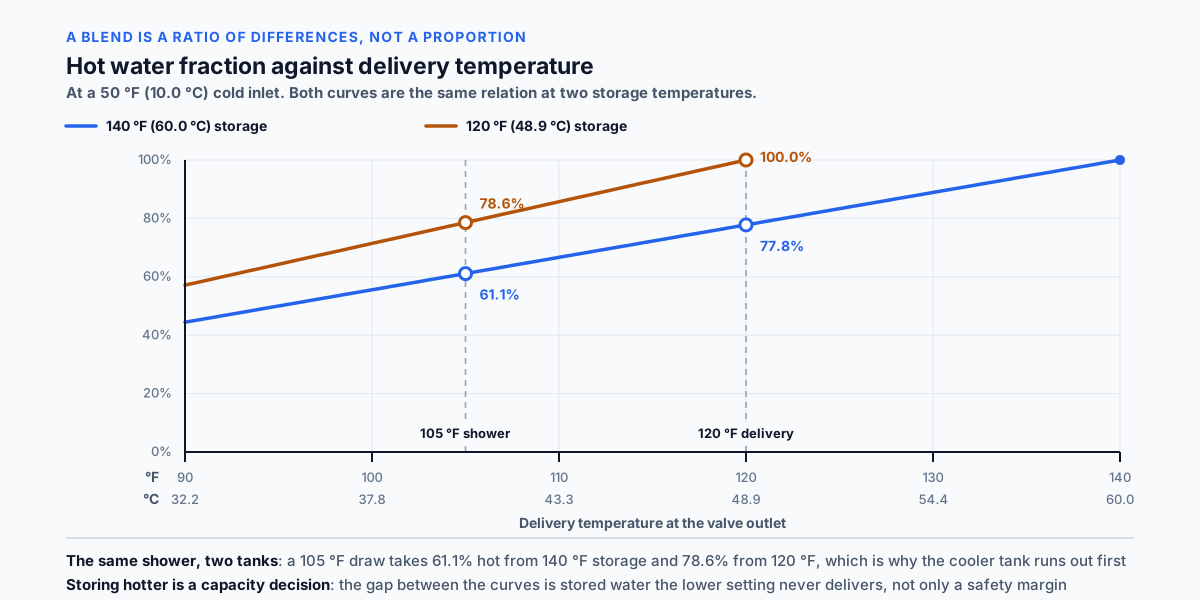
Change the delivery temperature and the ratio moves sharply. A 105 F shower from the same supplies is 55 over 90, which is 61.1 percent hot. That is a large change for a 15 degree difference in delivery.
Change the storage temperature and it moves the other way. That same 105 F shower from 120 F storage is 55 over 70, which is 78.6 percent hot. The same shower draws 61 percent hot from a 140 F tank and 79 percent from a 120 F one, which is the arithmetic behind a complaint usually blamed on tank size.
And the cold supply is in the equation too, which is the part most designs treat as fixed. That is covered in its own section below.
Stored Water Multiplier
Read the blend relationship backwards and it answers a different question: how much tempered water does a tank of hot water actually produce?
The multiplier is the hot supply temperature minus the cold temperature, divided by the delivery temperature minus the cold temperature. It is the reciprocal of the hot fraction, and it is greater than one whenever the storage is hotter than the delivery.
At 140 F storage, 50 F cold and 120 F delivery the multiplier is 1.286. A 40 gallon heater produces 51.4 gallons of 120 F water, or 194.7 litres from 151.4.
At a 105 F shower delivery the multiplier is 1.636 and the same 40 gallon heater produces 65.5 gallons of shower water.
That is a capacity argument rather than a safety one, and ASSE names it as such: a side benefit of an ASSE 1017 valve is that it allows the water to be stored at a higher temperature, extending the amount of hot water available while reducing the chance of Legionella. Manufacturer literature puts the same point in design terms, that a mixing valve can reduce the size or BTU requirement needed for peak demand.
The consequence reaches back into water heater selection. A tank sized for a 120 F delivery without accounting for 140 F storage is about 29 percent larger than the system needs at a 50 F cold inlet.
Three things the multiplier does not include, and all three matter on a real draw. It does not include recovery, so a heater firing during the draw delivers more than the figure suggests. It does not account for stratification, which reduces the usable hot volume below the nominal tank size. And it does not include heat lost between the valve and the fixture, so the temperature arriving at a distant tap is lower than the setpoint. The figure describes tempered water at the valve outlet from the stored volume, and nothing further downstream.
Winter Versus Summer Cold Water Temperature
The cold supply temperature is an input to the blend, and it is the one variable in the calculation that changes without anyone touching the system.
ASSE defines cold water as 40 F to 70 F, which is the seasonal span of a mains inlet in most of the country. That is not a tolerance; it is the range the same tap actually delivers across a year.
Work the blend at both ends, for 140 F storage delivering 120 F. At a 40 F winter inlet the hot fraction is 80 over 100, which is 80.0 percent. At a 70 F summer inlet it is 50 over 70, which is 71.4 percent.
So the same delivered gallon costs about 12 percent more hot water in winter. The multiplier moves with it in the same direction: 1.250 in winter against 1.400 in summer, so a 40 gallon tank produces 50 gallons of 120 F water in January and 56 in July.
That is why a system runs short in a season rather than failing outright. Nothing about the valve, the heater or the fixtures changed. The tank is simply emptying faster because each gallon out of the tap is taking more out of it.
The design consequence is which figure to use. For capacity, use the coldest expected inlet, because that is the condition the system has to survive. For the blend fractions, both ends are worth seeing, because a valve sized on summer figures will be drawing a larger hot fraction all winter.
The same seasonality reaches the valve duty. A higher hot fraction means the hot port is passing more of the total flow, which matters where a valve is near the ends of its rated range.
Mixing Valve Flow Range
A thermostatic mixing valve is specified by a range rather than by a capacity, and the range is the part that decides whether it works.
Every published valve carries a minimum and a maximum flow, and between them the valve holds its stated accuracy. Outside them it does not. One published series is rated from 0.5 to 12 gallons per minute, which is 1.9 to 45.4 litres per minute. Group control valves are described at 14 to 51 gallons per minute at 45 psi, which is 53 to 193 litres per minute.
That last phrase carries a condition that is easy to drop and it changes the number. A published range is quoted at a stated pressure differential across the valve. Change the differential and the range changes with it, so a range is a point on a flow chart rather than a fixed property of the device. A range used without knowing its pressure basis is preliminary, and this calculator says so when the differential is not entered.
ASSE approaches the same question from the accuracy side and gives a table rather than a single figure. For ASSE 1017 valves the allowable temperature fluctuation is plus or minus 3 F from 0 to 5 gallons per minute, plus or minus 5 F from 5 to 40, and plus or minus 7 F above 40. Those bands are 0 to 18.9, 18.9 to 151.4 and above 151.4 litres per minute, and the tolerances are 1.7, 2.8 and 3.9 Celsius degrees.
The table is introduced with the instruction that valves must be sized to match the flow requirements of the system, which makes the accuracy part of the sizing rather than a footnote on a datasheet. A larger valve is not just a larger valve; it is a less accurate one, and the setpoint has to move down to compensate.
Two figures are therefore needed to size a valve rather than one. The design flow sets the upper end. The minimum expected flow sets the lower end, and it is the harder of the two, which the next section covers.
Why Not to Oversize a Mixing Valve
On most components a size up is a margin. On a thermostatic mixing valve it is a failure, and manufacturer literature states the instruction in capitals: all thermostatic water mixing valves have limitations, they will not provide the desired accuracy outside of their flow capacity, consult the flow capacity chart and do not oversize.
The reason is the bottom of the range rather than the top.
Take a master valve chosen to pass a building morning peak of 45 gallons per minute, with a rated range of 5 to 50. At the peak it is comfortably inside its range. At two in the morning, when one lavatory runs at half a gallon per minute, it is an order of magnitude below its rated minimum.
At that flow the valve is not controlling. What leaves it is whatever the supplies give it, and on a system storing at 140 F that is a scald exposure rather than a comfort complaint. The building spends far more hours at the low end than at the peak, so the condition is not an edge case; it is most of the year.
The remedy is not a larger valve, and this is where the instinct does the most damage. A larger valve raises the rated minimum, which moves the low end further out of reach and makes the problem worse at exactly the hours it already fails. Where the required range is wider than a single valve covers, the answer is parallel or staged valves, or separate point of use protection so that the master valve is not the only thing standing between the storage temperature and a fixture.
The same argument applies at the fixture. Published guidance for shower valves notes that the showerhead flow rate must not be less than the manufacturer published minimum flow rate for the valve, so a low flow showerhead fitted to a valve with a higher minimum has the same problem at a smaller scale.
Sizing a mixing valve therefore starts with the smallest real draw rather than the largest. If only one figure is known, the minimum is the more useful one.
ASSE 1017 Versus ASSE 1070 Versus ASSE 1016
ASSE publishes a separate performance standard for each place a temperature control device can sit, and they are not interchangeable. The differences are set out in a matrix in the ASSE white paper on temperature control devices, and the columns that matter are what each device protects against and where it is installed.
ASSE 1017 covers temperature actuated mixing valves for hot water distribution systems. Scald protection: no. Thermal shock protection: no. Installed at, or near, the source. Downstream mixing allowed. Application recorded as temperature control for hot water distribution systems only, with additional downstream safety devices required.
ASSE 1016 covers automatic compensating valves for individual showers and tub shower combinations. Scald protection: yes. Thermal shock protection: yes. Installed at the point of use, with no further mixing downstream, and the final temperature adjusted by the user.
ASSE 1070 covers water temperature limiting devices for individual or multiple fixtures. Scald protection: yes. Thermal shock protection: no. Installed near, or integral to, plumbing fixture fittings, with the outlet adjustable up to a maximum of 120 F.
ASSE 1069 covers automatic temperature control mixing valves for single pipe gang showers and sitz baths. Scald protection: yes. Thermal shock protection: yes. Installed where the bather has no access to the temperature adjustment means, and designed to be the final temperature control.
Three more appear in the same matrix and are worth knowing. ASSE 1062 covers temperature actuated flow reduction valves, which reduce flow to a trickle within five seconds of the outlet exceeding a preset actuation temperature not to exceed 120 F. ASSE 1066 covers in-line pressure balancing valves, which give thermal shock protection for pressure disturbances only and no scald protection if an incoming temperature changes. ASSE 1071 covers valves supplying tepid water to plumbed emergency equipment, which by themselves do not meet ANSI Z358.1.
Read down the protection columns and one row stands out. ASSE 1017 is the only listing in the matrix with no in both. That is the subject of the next section.
Master Mixing Valve Is Not Scald Protection
This is the single most consequential thing on the page, and it is the one most often assumed the other way round.
A master mixing valve at the water heater does not protect anyone from scalding. ASSE states it in three separate ways in the same document.
In the matrix, ASSE 1017 devices are recorded as providing no scald protection and no thermal shock protection, with the application described as temperature control for hot water distribution systems only and additional downstream safety devices required.
In the device description, ASSE 1017 valves shall be installed at or near the outlet of the hot water source only, and are not intended for point of use applications. Used alone they do not provide thermal shock protection or adequate scald protection.
And in a worked question, asked because installers keep asking it: installing a device listed to ASSE 1017 at the water heater will not provide adequate scald protection.
The reason is what the valve is controlling. A master valve holds the distribution temperature steady against changes in the storage temperature and the incoming supplies. It does not know what is happening at a fixture, it does not respond to a toilet flushing on the same branch, and it does not limit what a user can select at the tap.
So the two devices are in series and neither replaces the other. The master valve solves the storage problem: it lets the tank sit at 140 F for Legionella control while the distribution runs cooler. The fixture device solves the user problem: it limits or compensates what arrives at the outlet. Removing either one leaves a real exposure.
Federal design guidance shows both requirements arriving together. It sets storage at not less than 140 F, requires a master mixing valve under ASSE 1017 to bring the distribution down to 131 F, and then notes that on existing systems steps must be taken to avoid scalding occupants at that distribution temperature. That last clause is the fixture level requirement, stated from the other direction.
Multi-Listed Mixing Valves
Many valves carry more than one ASSE listing. One published series is listed to ASSE 1017, ASSE 1069 and ASSE 1070 at the same time, and the natural reading is that such a valve can do all three jobs at once.
ASSE addresses that reading directly and the answer is no.
The rule is that the listing follows the installation position rather than the label. A device listed to multiple standards installed at the water heater to regulate the distribution temperature serves as an ASSE 1017 point of source application only. In that position it provides temperature control, and it does not provide the required scald protection.
The white paper works through the case that prompts the question. A plumber proposes installing a multi listed valve at the water heater with its limit stop set to 110 F, intending it to control the distribution temperature and prevent scalding at the fixtures in one device. The answer is that the device will not be able to provide the required scald protection in this application, and that further point of use temperature control devices must be installed as required.
The underlying principle is stated plainly: a single device should not be installed to control the entire temperature of the distribution system while simultaneously serving the needs of a fixture. Those are two jobs with different response requirements at two different places in the system.
What the multiple listing does buy is flexibility in specification. The same product can be stocked for either position, and it will perform to whichever standard applies where it is fitted. What it does not buy is a device count of one where the design needs two.
Setpoint Margin and Valve Accuracy
A limit is not a setpoint, and the gap between them is the valve own published tolerance.
Every thermostatic mixing valve has an allowable temperature fluctuation. A published point of use series states plus or minus 3 F across its rated range. ASSE 1017 publishes the figure by flow band for master valves: plus or minus 3 F from 0 to 5 gallons per minute, plus or minus 5 F from 5 to 40, and plus or minus 7 F above 40.
Set a valve to a limit and it is permitted to exceed it. A 120 F setpoint on a valve with a 3 F tolerance may deliver 123 F, and the valve is performing exactly to specification while the installation is outside the limit. Set it to 119 F and it may still deliver 122 F. Only 117 F or lower holds a 120 F limit on that valve.
The arithmetic is the limit minus the tolerance, and it moves with the flow band. Holding a 120 F limit needs a setpoint of 117 F on a small valve, 115 F in the middle band and 113 F above 40 gallons per minute. Holding a project limit of 115 F needs 112, 110 and 108 F respectively.
The manufacturer recommendation of a maximum of 110 F for shower and bathing fixtures works the same way: a 3 F valve needs a setpoint of 107 F to hold it.
Two practical points follow. A larger valve needs a lower setpoint for the same limit, which is a second reason not to oversize beyond the flow argument. And the tolerance to use is the one published for the actual product and its listing. The ASSE 1017 bands are published in ASSE 1017 for ASSE 1017 devices, so they do not transfer to an ASSE 1070 or ASSE 1016 device, which carries its own figure.
What Is a Mixing Valve
A mixing valve blends hot and cold water to produce water at a controlled temperature. In domestic hot water systems it exists to resolve a contradiction that has no other solution.
Water has to be stored hot. Federal design guidance sets storage at not less than 140 F to suppress Legionella, and published guidance citing ASSE puts the figure for killing 99 percent of the bacteria at 140 F over 32 minutes.
Water has to be delivered cool. The same published guidance notes that water at 140 F causes a third degree burn in five seconds. ASSE reports that hot water from the tap accounts for more than 25 percent of all scald burns in children, with the elderly and the physically impaired at increased risk.
The two requirements are the same temperature and they point in opposite directions. A mixing valve is the device that lets a system store at 140 F and deliver at 120 F or lower.
There is more than one kind, and they are not interchangeable. A master or system valve at the heater tempers the whole distribution system. A point of use device limits the temperature at a fixture. A shower valve compensates for pressure and temperature changes while someone is standing under it. ASSE publishes a separate performance standard for each, and the white paper setting out where each belongs was written because inspectors and installers kept asking whether one device could be used in place of another.
The answer, in most of the cases people ask about, is no.
Key Facts
- The hot fraction of a blend is the delivery temperature minus the cold temperature, divided by the hot supply temperature minus the cold temperature. It is a ratio of temperature differences and not a proportion.
- Delivering 120 F from 140 F storage with 50 F cold water takes 77.8 percent hot and 22.2 percent cold. Delivering a 105 F shower from the same supplies takes 61.1 percent hot.
- Delivering that same 105 F shower from 120 F storage takes 78.6 percent hot, which is why a tank set at 120 F runs out of shower water faster than one set at 140 F.
- ASSE defines cold water as 40 F to 70 F. At 140 F storage delivering 120 F, a 40 F inlet needs 80.0 percent hot and a 70 F inlet needs 71.4 percent, so the same delivered gallon costs about 12 percent more hot water in winter.
- The stored water multiplier is the hot supply temperature minus the cold temperature, divided by the delivery temperature minus the cold temperature.
- At 140 F storage, 50 F cold and 120 F delivery the multiplier is 1.286, so a 40 gallon tank behaves like 51.4 gallons. At a 105 F delivery it is 1.636 and the same tank behaves like 65.5 gallons.
- The multiplier moves with the season too: 1.250 at a 40 F inlet and 1.400 at a 70 F inlet, for the same 140 F storage and 120 F delivery.
- ASSE notes as a side benefit of ASSE 1017 valves that they allow the water to be stored at a higher temperature, extending the amount of hot water available and reducing the chance of Legionella.
- ASSE records ASSE 1017 master valves as providing no scald protection and no thermal shock protection, for temperature control of hot water distribution systems only, with additional downstream safety devices required.
- ASSE 1017 valves shall be installed at or near the outlet of the hot water source only, and are not intended for point of use applications.
- ASSE 1017 publishes the allowable temperature fluctuation by flow rate: plus or minus 3 F from 0 to 5 gallons per minute, plus or minus 5 F from 5 to 40, and plus or minus 7 F above 40. The table is introduced with the instruction that valves must be sized to match the flow requirements of the system.
- A limit is not a setpoint. Holding a 120 F limit needs a setpoint of 117 F at plus or minus 3 F, 115 F at 5 F, and 113 F at 7 F.
- ASSE 1070 water temperature limiting devices allow the outlet temperature to be adjusted up to a maximum of 120 F. They provide scald protection only and no thermal shock protection.
- ASSE 1016 automatic compensating valves for individual showers and tub shower combinations provide both scald and thermal shock protection, with no further mixing downstream.
- ASSE 1069 automatic temperature control mixing valves are for single pipe gang showers and sitz baths, installed where the bather has no access to the adjustment, and provide both scald and thermal shock protection.
- ASSE 1062 temperature actuated flow reduction valves reduce flow to a trickle within five seconds of the outlet exceeding a preset actuation temperature not to exceed 120 F. During that five second response the bather may be exposed to temperatures above the setpoint.
- ASSE 1066 in-line pressure balancing valves provide thermal shock protection for pressure disturbances only and do not provide scald protection if an incoming temperature changes.
- ASSE 1071 valves provide tepid water for plumbed emergency equipment and by themselves do not meet ANSI Z358.1.
- A device listed to multiple standards installed at the source is considered an ASSE 1017 device, and that does not negate the requirement for an ASSE 1016, 1069 or 1070 device at the point of use where one is required.
- A thermostatic mixing valve controls only within its rated flow range. Manufacturer literature states that valves will not provide the desired accuracy outside their flow capacity and instructs designers not to oversize.
- A published valve range is quoted at a stated pressure differential, so it is a point on a flow chart rather than a fixed property of the device. One published series runs 0.5 to 12 gallons per minute; group control valves are described at 14 to 51 at 45 psi.
- Supplementary check valves are recommended for ASSE 1017 devices that do not include integral check valves, to prohibit crossflow of hot or cold water through the valve.
- ASSE defines hot water as not less than 120 F, tempered water as a mixture producing warm water suitable for use, and tepid water as 60 F to 100 F for emergency equipment.
Applications
- An engineer specifying a water heater works out how much smaller the tank can be if the system stores at 140 F and tempers down, rather than storing at the delivery temperature.
- A contractor adding a mixing valve to an existing heater checks whether the valve will still control at the smallest overnight draw, not just at the morning peak.
- A designer working out why a shower runs hot at night finds the master valve sitting below its rated minimum flow at that hour.
- A plumber choosing between a master valve and a fixture device reads what each listing actually protects against, and finds that the master valve protects against neither scalding nor thermal shock.
- A specifier who has been offered a triple listed valve finds that installing it at the heater makes it an ASSE 1017 device and does not remove the need for a fixture level device.
- A facilities manager setting a valve to a 120 F limit finds that the setpoint has to sit below the limit by the valve own tolerance, which on a large master valve is 7 F.
- A designer comparing summer and winter operation sees why a system that was comfortable in August runs short in January with nothing having changed.
Example Calculations
Example 1. The blend is not a proportion
Given: 140 F hot supply, 50 F cold supply, 120 F delivery.
The hot fraction is 120 minus 50, divided by 140 minus 50, which is 70 over 90, or 0.778.
Result: 77.8 percent hot and 22.2 percent cold. At a 4 gallon per minute delivery that is 3.11 gallons per minute of hot water and 0.89 of cold.
Example 2. The shower blend, and why storage temperature decides it
Given: a 105 F shower delivery with 50 F cold, from two different storage temperatures.
From 140 F storage the hot fraction is 55 over 90, which is 61.1 percent. From 120 F storage it is 55 over 70, which is 78.6 percent.
Result: the same shower draws 61 percent hot from a 140 F tank and 79 percent from a 120 F tank. That is the arithmetic behind a complaint people usually blame on tank size.
Example 3. Storing hotter multiplies the tank
Given: a 40 gallon heater, 50 F cold water, 120 F delivery.
At 140 F storage the multiplier is 90 over 70, which is 1.286, and the effective volume is 51.4 gallons. At a 105 F shower delivery the multiplier is 90 over 55, which is 1.636, and the effective volume is 65.5 gallons.
Result: the same tank behaves like a 51 gallon one for 120 F water and a 65 gallon one for shower water. The figure describes tempered water at the valve outlet and excludes recovery, stratification and downstream heat loss.
Example 4. Winter and summer are different systems
Given: 140 F storage delivering 120 F, at the two ends of the ASSE cold water definition of 40 F to 70 F.
At a 40 F winter inlet the hot fraction is 80.0 percent and the multiplier is 1.250. At a 70 F summer inlet the hot fraction is 71.4 percent and the multiplier is 1.400.
Result: the same delivered gallon costs about 12 percent more hot water in winter, and a 40 gallon tank produces 50 gallons of 120 F water in January against 56 in July.
Example 5. The setpoint that is not the limit
Given: a point of use application at a 120 F limit, on a valve with a plus or minus 3 F tolerance.
Setting the valve to 120 F permits a delivery of 123 F. Setting it to 119 F permits 122 F. Only a setpoint of 117 F or lower holds the limit.
Result: a limit is not a setpoint, and the difference is the valve published tolerance. The valve is performing to specification in every one of those cases.
Example 6. The tolerance depends on the flow
Given: a master valve checked at three design flows against a 120 F limit, using the ASSE 1017 bands.
At 4 gallons per minute the tolerance is 3 F and the setpoint ceiling is 117 F. At 20 gallons per minute it is 5 F and 115 F. At 50 gallons per minute it is 7 F and 113 F.
Result: the same limit produces three different setpoints depending on the size of the valve. ASSE introduces that table with the instruction that valves must be sized to match the flow requirements of the system, so the accuracy is part of the sizing rather than a datasheet footnote.
Example 7. The valve that fails at two in the morning
Given: a master valve chosen to pass a peak of 45 gallons per minute, rated 5 to 50, on a building whose smallest overnight draw is one lavatory at 0.5 gallons per minute.
Result: at the peak it is inside its range and at 0.5 gallons per minute it is an order of magnitude below its rated minimum. Outside its range it does not control, and on a 140 F system that is a scald exposure. The remedy is not a larger valve, which raises the minimum further; it is parallel or staged valves or separate point of use protection.
Example 8. The master valve that protects nobody
Given: a master mixing valve at the heater set to 120 F, with no fixture level devices downstream.
Result: the distribution is tempered and the fixtures are not protected. ASSE records ASSE 1017 devices as providing neither scald nor thermal shock protection and answers the question directly: installing a device listed to ASSE 1017 at the water heater will not provide adequate scald protection.
Example 9. The triple listed valve that still needs a second device
Given: a valve listed to ASSE 1017, 1069 and 1070, installed at the water heater with its limit stop set to 110 F, intended to control the distribution temperature and prevent scalds at the same time.
Result: not a correct installation. A multi listed device installed at a water heater to regulate distribution temperature serves as an ASSE 1017 point of source application only, provides temperature control rather than the required scald protection, and point of use devices must still be installed as required. The listing that applies is the one matching where the device sits.
Example 10. Delivery equal to the hot supply
Given: 120 F hot supply, 50 F cold supply, 120 F delivery.
The hot fraction is 70 over 70, which is 1.00, and the multiplier is 1.00.
Result: 100 percent hot, no cold water required by the energy balance, and no capacity gained. That is a valid configuration rather than an error: the valve is present for temperature control or because a listing requires it, and it is not extending the storage.
Example 11. A candidate range with no pressure basis
Given: a candidate valve entered as 5 to 40 gallons per minute, with no pressure differential stated.
Result: the range check runs and is reported as preliminary. A published range is quoted at a stated differential across the valve, so the same valve shows a different range at a different pressure. Without the basis, a design flow near either end of the range cannot be confirmed, and the manufacturer chart at the system actual differential governs.
Example 12. Handwashing and bathing are different questions
Given: a point of use device at 120 F, considered first at a lavatory and then at a shower.
Result: at the lavatory the question is scald protection, which is the ASSE 1070 case, with the outlet adjustable to a maximum of 120 F. At the shower the question is scald protection and thermal shock protection together, which is the ASSE 1016 case for individual showers and tub shower combinations, and manufacturer guidance recommends a maximum of 110 F for bathing fixtures rather than 120. The blend arithmetic is identical and the device and the limit are not.
Example 13. A project limit overrides the general figures
Given: a project or local code limit of 115 F, on a valve with a plus or minus 3 F tolerance.
Result: the setpoint ceiling is 112 F rather than the 117 F that a 120 F limit would give. Where a project or jurisdiction sets its own maximum it governs over the manufacturer and ASSE figures used as defaults here, and the calculator uses it for the margin check when entered.
Example 14. Emergency tempering is a different framework
Given: an emergency eyewash or emergency shower application.
Result: no blend is returned. Plumbed emergency equipment is covered by ASSE 1071 for the tempering valve and by ANSI Z358.1 for the delivered temperature, with tepid water defined as 60 F to 100 F rather than the domestic hot water figures used here. ASSE also notes that an ASSE 1071 valve by itself does not meet the emergency equipment standard, so the device and the system requirement are separate questions.
Standards & References
- [ASSE International, Guidelines for Temperature Control Devices in Domestic Hot Water Systems](https://asse-plumbing.org/media/pbfltxqk/asse_guidelines_for_temp_control_devices.pdf) A white paper by the ASSE Scald Awareness Task Group and the primary source for the device distinctions on this page: the ASSE 1017 allowable temperature fluctuation table by flow rate, the statement that ASSE 1017 valves shall be installed at or near the outlet of the hot water source only and are not intended for point of use applications, the note that they allow water to be stored at a higher temperature and extend the amount of hot water available, the 120 F maximum for ASSE 1070 devices, the treatment of devices listed to multiple standards, the definitions of cold, hot, tempered and tepid water, and the matrix of which listing provides scald protection and which provides thermal shock protection.
- [ANSI/ASSE 1017-2009, Performance Requirements for Temperature Actuated Mixing Valves for Hot Water Distribution Systems](https://webstore.ansi.org/standards/asse-sanitary/ansiasse10172009) The standard itself, for the scope of the master valve listing. The allowable fluctuation bands quoted on this page are published in this standard for devices listed to it, and they do not transfer to a device listed to ASSE 1016, 1069 or 1070.
- [Watts, Thermostatic Mixing Valves reference page](https://www.watts.com/resources/references-tools/thermostatic-mixing-valves) Manufacturer guidance that delivery to fixtures intended for bathing or washing should always be controlled by valves listed to ASSE 1016 Type T or ASSE 1070, the recommendation of a maximum of 110 F for shower and bathing fixtures, the requirement for check valves in ASSE 1017 applications, and the note that these valves allow the heater to be operated at higher temperatures and can reduce the size or BTU requirement for peak demand.
- [Watts LFMMV series product page](https://www.watts.com/products/plumbing-flow-control-solutions/mixing-valves/lavatory-mixing-valves/lfmmv) A published valve range of 0.5 to 12 gallons per minute with an accuracy of plus or minus 3 F, listed to ASSE 1017, 1069 and 1070, which is an example of the multiple listing case the ASSE white paper addresses.
- [Leonard Valve, product literature](https://www.leonardvalve.com/api/file/14371/pdf/S-2028-LF.pdf) The caution that all thermostatic water mixing valves have limitations, that they will not provide the desired accuracy outside of their flow capacity, and the instruction to consult the flow capacity chart and not to oversize. The instruction appears in capitals in the source.
- [UpCodes, Sizing Hot Water Systems](https://up.codes/s/sizing-hot-water-systems) Federal design guidance setting the storage temperature at not less than 140 F to limit Legionella growth, requiring a master mixing valve under ASSE 1017 to lower the temperature to 131 F immediately downstream of the storage tank, and requiring at least 122 F throughout recirculation piping where a recirculation pump is used.
- [School of Professional Home Inspection, Hot Water Mixing Valves](https://schoolofprofessionalhomeinspection.com/lib/HotWaterMixingValves.pdf) A manufacturer brochure setting out the ASSE 1016, 1017 and 1070 distinctions and stating that ASSE 1017 listed devices should never be used to deliver water directly to the user.
- ASHRAE Standard 188, Legionellosis: Risk Management for Building Water Systems Named as the boundary of this page rather than applied by it. The storage temperature arrives here as an input, and Legionella risk assessment belongs to a water management plan under this standard.
- Note on attribution The device distinctions, the flow dependent tolerance table, the 120 F maximum for ASSE 1070 devices, the multiple listing treatment and the water definitions are from the ASSE white paper, read directly. The 110 F bathing recommendation and the do not oversize instruction are manufacturer guidance rather than ASSE or code requirements and are attributed as such throughout. The 140 F storage and 131 F distribution figures are from federal design guidance. Published valve flow ranges are examples from product data quoted at a stated pressure differential, not properties of the device class. Local codes carry their own maximum temperature requirements which vary by jurisdiction and fixture type, and where a project or local limit applies it governs over the figures used here. The Authority Having Jurisdiction has final approval of any installation, and manufacturer installation requirements may exceed the prevailing code.
Units
Temperatures are entered and reported in Fahrenheit and Celsius. A temperature level converts with the offset: Celsius equals Fahrenheit minus 32, divided by 1.8. The figures on this page are 140 F as 60.0 C, 131 F as 55.0 C, 122 F as 50.0 C, 120 F as 48.9 C, 110 F as 43.3 C, 105 F as 40.6 C, 70 F as 21.1 C, 50 F as 10.0 C and 40 F as 4.4 C.
A temperature difference converts without the offset, by dividing by 1.8. The ASSE 1017 tolerances of plus or minus 3, 5 and 7 F are 1.7, 2.8 and 3.9 Celsius degrees. Applying the level rule to a 3 F tolerance returns minus 16.1 C, which is not a tolerance, and that distinction is the one to watch when switching systems on this page.
Flow is entered in gallons per minute or litres per minute at 3.785411784. The ASSE 1017 flow bands of 0 to 5, 5 to 40 and above 40 gallons per minute are 0 to 18.9, 18.9 to 151.4 and above 151.4 litres per minute. The published valve ranges of 0.5 to 12 and 14 to 51 gallons per minute are 1.9 to 45.4 and 53.0 to 193.1 litres per minute.
Volume is entered in gallons or litres at the same factor. A 40 gallon tank is 151.4 litres, and its effective 51.4 gallons at 120 F delivery is 194.7 litres.
The pressure differential a published range is quoted at is entered in psi or kPa at 6.894757, so 45 psi is 310 kPa.
The hot fraction, the cold fraction and the stored water multiplier are dimensionless and identical in both systems.
The internal unit selector governs the fields, labels, math, on-screen result and any exported result, and it takes priority over any site-wide unit switch. Switching converts the values you entered rather than reinterpreting them.
Limitations
- This calculator computes a blend and a valve duty. It does not select a valve, and matching a product means reading its flow capacity chart at the pressure differential available in the system.
- It does not derive valve pressure drop or flow coefficients, and it does not check supply pressure balance, minimum pressure differential, check valve layout or strainer selection. Candidate valve data and the manufacturer installation instructions govern.
- A published valve flow range is quoted at a stated pressure differential and is a point on a chart rather than a property of the device, so a range entered without its basis is preliminary.
- The ASSE 1017 tolerance bands apply to ASSE 1017 devices. On any other listing the accuracy published for the actual product governs, and this calculator asks for it rather than borrowing a figure from a different standard.
- The stored water multiplier describes tempered water available at the valve outlet from the stored volume. It does not account for recovery during the draw, for stratification reducing the usable hot volume, or for heat lost downstream of the valve.
- The blend is an energy balance with no loss term. The temperature arriving at a distant fixture will be lower than the valve setpoint unless the run is short, insulated or recirculated.
- Hydronic heating mixing valves are a different device on a closed circuit, sized by different flow, temperature and control requirements, and are outside this calculator.
- Emergency eyewash and emergency shower tempering is a different requirement with its own listing under ASSE 1071 and its own delivery temperature framework under ANSI Z358.1, and is outside this calculator.
- The storage temperature is a water management decision that arrives here as an input. Legionella risk assessment belongs to a water management plan under ASHRAE 188 and is not performed on this page.
- Which fixture level device a code requires, and where, depends on the fixture type and the jurisdiction. This page names the ASSE listings and what each protects against; the Authority Having Jurisdiction has final approval of any installation, and manufacturer installation requirements may exceed the prevailing code.
Common Mistakes to Avoid
- Assuming a mixing valve is a half and half blend. The hot fraction is a ratio of temperature differences. Delivering 120 F from 140 F with 50 F cold takes 77.8 percent hot.
- Treating the cold inlet as a constant. ASSE defines cold water as 40 F to 70 F, and the blend moves across that span. The same delivered gallon costs about 12 percent more hot water at the winter end.
- Installing a master mixing valve and calling the system protected. ASSE records ASSE 1017 devices as providing neither scald nor thermal shock protection, and states that additional downstream safety devices are required.
- Buying a multiple listed valve to avoid a second device. A device installed at the source is an ASSE 1017 device regardless of what else it is listed to, and the fixture level requirement stands.
- Setting the valve to the limit. A limit is not a setpoint. With a plus or minus 3 F tolerance a 120 F setpoint permits 123 F, and the setpoint has to sit below the limit by at least the tolerance.
- Using one tolerance figure for every valve. ASSE 1017 publishes the allowable fluctuation by flow rate, so a valve above 40 gallons per minute carries plus or minus 7 F and needs a setpoint 7 F below the limit.
- Using the ASSE 1017 tolerance for a device listed to something else. Those bands are published in ASSE 1017 for master distribution valves. Point of use and shower devices are checked against their own listing and product data.
- Sizing the valve for the peak alone. The failure is at the bottom of the range. A valve that covers a morning peak may sit below its rated minimum overnight, and outside its range it does not control.
- Answering a low flow problem with a larger valve. A larger valve raises the rated minimum and moves the low end further out of reach. Parallel or staged valves, or separate point of use protection, are the answer.
- Using a published flow range without its pressure basis. Ranges are quoted at a stated pressure differential and change with it.
- Reading the thermostat setting as the valve inlet temperature. Stratification, the recirculation return location and pipe heat loss all sit between the two.
- Ignoring the five second exposure on a flow reduction device. An ASSE 1062 valve reduces flow to a trickle within five seconds of exceeding its setpoint, and during that response the bather may be exposed to temperatures above it.
- Treating the multiplier as delivered capacity. It describes tempered water at the valve outlet and excludes recovery, stratification and downstream heat loss.
Frequently Asked Questions
How do I calculate the hot and cold water for a mixing valve?
Why is the blend not 50/50?
Does a mixing valve increase hot water capacity?
What temperature should I set a mixing valve to?
Does a master mixing valve protect against scalding?
Can one valve do both jobs if it is listed to several standards?
Can a mixing valve be too big?
Why does my hot water run out faster in winter?
What is the difference between ASSE 1017 and ASSE 1070?
What is the difference between ASSE 1016 and ASSE 1070?
Why does the ASSE 1017 accuracy depend on flow?
Does the stored water multiplier include heater recovery?
Can I use this calculator for a hydronic heating mixing valve?
Can I use this for emergency eyewash or emergency shower tempering?
Frequently Used Together
Engineers often use these calculators in combination for complete project workflows:
Related Calculators
Explore similar calculators that might be useful for your project:
Plumbing Quick Reference — Keep It On Your Phone On Site
A 10-page field reference for catching pressure, velocity, slope, and pump-sizing mistakes before you order pipe, close a wall, or add a booster.
- Velocity limits, fixture pressure minimums, drain slope, and the 80 psi ceiling in one table
- Worked examples that show why a single pressure number gives four different answers
- Keep it on your phone, or print the two field-check pages
Free PDF. Calculators stay free. Unsubscribe anytime.
Calculate
This selector governs every field, label, result and export on this page, and it takes priority over the site header switch. The page opens in your site-wide preference and follows the header until you use this selector; from the first time you use it, including a selection of the system already showing, the header moves the rest of the site and leaves this page where you put it. Switching converts the values you entered rather than reinterpreting them, so 140 F becomes 60.0 C and returns to exactly 140 when you switch back. Watch one distinction here: the three temperatures and the limit are levels and convert with the 32 degree offset, while the valve accuracy is a difference and converts by dividing by 1.8 alone. A 3 F tolerance is 1.7 Celsius degrees, not minus 16.1.
The Application
This is the first question because it decides the listing, the temperature limit and whether this is the right page. Two of the seven answers end the calculation: a hydronic heating mixing valve works on a closed heating circuit, and an emergency eyewash or shower is covered by ASSE 1071 and ANSI Z358.1 with tepid water defined as 60 F to 100 F. Both are commonly meant by the words mixing valve and neither is this calculation.
The Three Temperatures
Use the temperature actually entering the hot port, not the thermostat label. Tank stratification, the location of the recirculation return and heat lost in the piping between the heater and the valve can all make the two differ, and absorbing that difference is one of the things a thermostatic valve is there to do. This is a temperature level, so it converts with the 32 degree offset.
This is a seasonal figure rather than a constant. ASSE defines cold water as 40 F to 70 F, which is the span a mains inlet actually delivers across a year. Use the coldest expected inlet for capacity, because that is when the tank empties fastest, and note that the blend fraction moves with it: the result works both ends for you.
What you want the valve to produce. A delivery equal to the hot supply is a valid entry and returns no blend: the valve is present for control or for a listing rather than for capacity. A delivery above the hot supply is not, because a mixing valve blends down and has no heat source of its own.
Flows and Storage (all optional)
The largest flow the valve has to pass. It gives the hot and cold flows and the upper end of the valve duty, and on a master valve it also selects the ASSE 1017 allowable fluctuation band when no product tolerance is entered. Leave it blank and the blend and the multiplier are still returned.
The smallest real draw through this valve while hot water can still be delivered. One lavatory, one shower at low flow, or on a master valve serving a recirculated system, the recirculation flow or the smallest fixture draw depending on the piping arrangement. Estimate it rather than skipping it: the low end is the end that fails, because a thermostatic valve does not control below its rated minimum.
The nominal volume of the water heater or storage vessel. Multiplied by the stored water multiplier it gives the tempered water available at the valve outlet, which is the figure that reaches back into water heater selection.
The Candidate Valve (all optional)
From the manufacturer flow capacity chart for a specific product. Below this flow the valve does not hold its stated accuracy, which the result treats as a failure rather than an advisory.
The upper end of the same published range. For scale, one point of use and system series is rated 0.5 to 12 gallons per minute, and group control valves are described at 14 to 51 gallons per minute at 45 psi.
A published range is quoted at a stated pressure differential across the valve, so it is a point on a flow chart rather than a fixed property of the device. Entered without it, the range check runs and is reported as preliminary.
The allowable temperature fluctuation published for the actual product. On a master application a blank field uses the ASSE 1017 band for the design flow: plus or minus 3 F from 0 to 5 gallons per minute, 5 F from 5 to 40, and 7 F above 40. On any other application a blank field is reported as not established rather than filled from those bands, because they are published in ASSE 1017 for ASSE 1017 devices and do not transfer to a device listed to something else. This is a temperature difference, so it converts by dividing by 1.8 with no offset.
Where a project specification or a local code sets a maximum delivery temperature, enter it and it governs the margin check. Left blank, a handwashing or bathing application uses the ASSE 1070 device maximum of 120 F and a bathing application also checks the 110 F manufacturer recommendation, while a master or gang shower application reports no applicable limit rather than assuming one.