Three Airflows Where Most Problems Have One
A machinery space produces three separate airflow figures before it produces an answer, and the relation between them is neither a sum nor a choice of the largest.
The engines need air to burn fuel. The space needs air to carry away the heat its machinery gives off. Those two statements suggest either adding the quantities or taking whichever is larger, and the standard governing the calculation does neither. It subtracts part of the combustion air from the thermal requirement first, then adds what remains to the combustion air, then checks the total against a floor set at one and a half times the combustion air alone.
Taking the larger would assume the two airflows can substitute for one another, and they cannot. Air drawn into the cylinders leaves through the exhaust and never returns to the space, so it plays no part in the extract balance. Adding them outright would count the same air twice, because that air passes through the machinery space on its way to the engine and picks up heat while it does. The correction between the two is what the standard supplies, and it has no equivalent in building ventilation, where nothing consumes the supply air on the way through.
The calculator follows that structure. It returns the combustion airflow, the gross thermal airflow, the corrected heat evacuation component, both checks and the result, which makes the intermediate quantities visible rather than hiding them behind a single number. That matters more here than in most ventilation calculations, because the answer can be produced by either of two mechanisms with nothing in the final figure to say which. An airflow governed by the sum moves when the heat emission assumption moves. An airflow governed by the floor does not move at all until the combustion air changes, and an engineer revising a heat balance has no way of knowing which case is in front of him from the airflow alone.
What follows covers where each of the three quantities comes from, why the correction between them exists and how large it is, at what heat load the floor takes over from the sum, and what the design conditions of the standard assume about the air the ship is operating in. The sequence of the arithmetic itself is set out on the calculator page and is not repeated here as the substance of the article.
Calculator Inputs: Power, Engine Type, Heat Fraction, Rise
Four fields and a unit toggle, of which one is a choice between two engine types and one is a fraction that has to come from somewhere other than the page.
Unit System. Imperial (HP, °F, CFM) or Metric (kW, °C, m³/s). The calculation runs in SI regardless of the selection, converting on the way in and on the way out, so the toggle changes the presentation and not the physical result.
Engine Power [HP or kW]. The total installed power of the group of diesel engines under consideration. For the worked example below, 1,000 kW (1,341 HP).
Engine Type. Two-stroke or four-stroke. The selection sets the specific mass flow of combustion air used where engine manufacturer data is not available, and that value differs between the two by 15 percent.
Radiated Heat Loss Factor [%]. The fraction of engine power that reaches the space as heat rather than leaving as work or through the exhaust. It belongs to the engine, not to the calculation, and it comes from the engine project guide.
Allowable Temperature Rise [°F or °C]. The permitted rise of the machinery space air above the ambient air entering it. The design basis of the standard puts a ceiling on this quantity, which the next sections return to.
The outputs are the combustion airflow, the gross thermal airflow, the corrected heat evacuation component, the two checks and the required ventilation airflow. Six figures where most ventilation calculations return one:
qc         = P × mad / ρ
Φ          = P × HL / 100
q_thermal  = Φ / (ρ × c × ΔT)
qh         = max(0, q_thermal − 0.4 × qc)
Q1         = qc + qh
Q2         = 1.5 × qc
Q_required = max(Q1, Q2)
The constants that do not appear as fields:
ρ    = 1.13 kg/m³ (0.0705 lb/ft³), air density at the
         design conditions of the standard
c    = 1.01 kJ/(kg·K) (0.241 BTU/(lb·°F)), specific heat
         capacity of air
mad  = 0.0020 kg/(kW·s) four-stroke, 0.0023 kg/(kW·s)
         two-stroke, specific mass flow of combustion air
What is not among the fields is as informative as what is. There is no field for diesel generators or boilers, which the standard treats as separate air consumers. There is no field for the heat given off by the exhaust system, the piping, the tanks or the switchboards, which the standard sums separately. There is no field for ambient temperature, because the design basis fixes it. And there is nothing about the resistance of the trunks, the louvres or the ducts, which decides the fan pressure and not the airflow.
Combustion Air Is a Mass, Not a Volume
The standard states the combustion air requirement as a mass flow per unit of engine power, and the distinction from a volume flow decides whether the figure survives a change of climate.
qc = P × mad / ρ

P     engine power, kW
        typically 500 to 25,000 kW (670 to 33,500 HP)
        for a main propulsion group
mad   specific mass flow of combustion air, kg/(kW·s)
        0.0020 four-stroke, 0.0023 two-stroke
        (0.00329 and 0.00378 lb/(HP·s))
ρ     air density at the design conditions, kg/m³
        1.13 (0.0705 lb/ft³)
An engine needs a certain quantity of oxygen for each unit of fuel it burns, which is to say a certain mass of air. The volume that contains that mass depends on temperature and humidity. Stating the requirement in volume units silently ties it to whatever conditions the volume was computed at, and nothing on the fan or in the trunk records what those conditions were.
The size of that silent tie is worth putting a number on. At a specific mass flow of 0.0020 kg/(kW·s):
At ρ = 1.204 kg/m³ (0.0752 lb/ft³), dry air at 20 °C (68 °F):
  0.001661 m³/(kW·s) = 2.62 CFM per HP

At ρ = 1.13 kg/m³ (0.0705 lb/ft³), the design conditions
of the standard:
  0.001770 m³/(kW·s) = 2.80 CFM per HP

Difference: 6.5 percent
That 6.5 percent is the price of moving from temperate to tropical air, and it falls on the wrong side of the ledger. A ship whose fans were sized to a volume requirement worked out for temperate conditions delivers less mass to its engines in the tropics than they need. The fan moves the same volume it always did, and no measurement of volumetric flow anywhere in the system will show anything wrong.
As for where the value itself comes from, the specific mass flow expresses the air an engine needs per unit of power including the excess air it runs with above stoichiometric. For a turbocharged marine diesel, a figure of the order of two thousandths of a kilogram per kilowatt-second corresponds to a typical combination of specific fuel consumption and excess air ratio, which is why the two engine types differ by roughly the ratio of their scavenging arrangements rather than by an arbitrary margin.
Per ISO 8861:1998, confirmed on review in 2022 and still the current edition: the combustion air requirement is stated as a mass flow per unit of engine power, so the volume it corresponds to follows from the air density at the design conditions rather than being fixed. The values in the standard apply where data for the specific engine is not available, and the manufacturer's stated air consumption takes precedence over them.
The Design Conditions Are Tropical, Not Comfortable
The density the calculation uses comes from a stated set of design conditions, and those conditions describe a ship working in the tropics rather than a machinery space in temperate weather.
Ambient temperature      35 °C (95 °F)
Relative humidity        70 percent
Atmospheric pressure     101.3 kPa (14.70 psia)
The density that follows is not assumed. It can be reconstructed from those three numbers, and doing so is worth the two lines it takes, because it shows how much of the 1.13 kg/m³ is temperature and how much is moisture:
Dry air at 35 °C:      353 / 308.15 = 1.146 kg/m³ (0.0715 lb/ft³)

Moist air at 70 % RH:
  saturation pressure at 35 °C ≈ 5.63 kPa
  vapour partial pressure = 0.70 × 5.63 = 3.94 kPa
  ρ = (101.3 − 3.94) / (0.287 × 308.15) + 3.94 / (0.4615 × 308.15)
    = 1.101 + 0.028 = 1.129 kg/m³ (0.0705 lb/ft³)
Water vapour has a lower molar mass than air, so humid air is lighter than dry air at the same temperature and pressure, which is the opposite of what most people expect from something described as heavy tropical air. Seventy percent relative humidity at 35 °C is a substantial moisture content, and it is what takes the density from 1.146 down to the 1.13 kg/m³ the standard adopts. A calculation carried out on dry air would return a higher density, a smaller volume for the same combustion mass, and an underestimate of the airflow.
Tropical conditions are used because a ship moves between climate zones and the ventilation has to work in the worst of them. A system sized on temperate air is a system that fails on a tropical passage, and there is no site-specific climate data to fall back on, because the site moves.
The same two numbers also fix the design environment inside the space. Ambient of 35 °C plus the permitted rise of 12.5 K gives 47.5 °C (117.5 °F) in the machinery space, and that is the temperature the equipment and the watchkeepers are expected to work at.
Per ISO 8861:1998 §4: the design conditions are an ambient temperature of 35 °C at 70 percent relative humidity and standard atmospheric pressure, which gives an air density of about 1.13 kg/m³ and describes a vessel operating in tropical conditions rather than a temperate machinery space.
Heat Emission and the Gross Thermal Airflow
The thermal side of the calculation starts with the fraction of engine power that leaves as heat into the space, and converts it into an airflow through the same sensible heat relation used in building ventilation.
Φ = P × HL / 100

Φ     heat emission into the space, kW
        50 kW (170,600 BTU/h) in the worked example
P     engine power, kW
HL    fraction of engine power reaching the space
        as heat, percent
q_thermal = Φ / (ρ × c × ΔT)

ρ     1.13 kg/m³ (0.0705 lb/ft³)
c     1.01 kJ/(kg·K) (0.241 BTU/(lb·°F))
ΔT    allowable temperature rise, K
        up to 12.5 K (22.5 °F) on the design basis
The product in the denominator is worth naming, because it is the quantity that does the work:
ρ × c = 1.13 × 1.01 = 1.1413 kJ/(m³·K)
That is the volumetric heat capacity of air at the design conditions: the energy a cubic metre of it carries away for each degree it is allowed to warm. Engineers working in imperial units will recognise its relative, the sensible heat constant of 1.08 that appears in duct calculations ashore. At the design conditions of this standard the same constant works out at 1.02 rather than 1.08, because 60 × 0.0705 × 0.241 = 1.02, and the hot humid air of the design basis is six percent lighter than the standard air the familiar figure assumes. The worked example below returns 7,736 CFM by either route, which is a useful check that the imperial and metric paths through the calculation are the same path.
The heat loss factor itself comes from the engine project guide, which states heat emission to the machinery space as a separate line. It varies with the insulation of the exhaust manifold and turbocharger, with the engine construction and with the operating condition, and it is the one input in this calculation that a designer cannot derive from anything else on the page. The 5 percent used in the worked example is an input to that example rather than a recommended value.
The airflow this gives is not yet the answer. It is the air that would be needed if all of the heat removal had to be done by air brought in for the purpose, and part of the heat is already being removed by air that is on its way somewhere else.
Per ISO 8861:1998 §6.1: heat emission from a diesel engine into the machinery space is taken as a percentage of engine power, and the airflow that would remove it follows from the volumetric heat capacity of air at the design conditions and the permitted temperature rise.
Why the Thermal Term Is Reduced by Part of the Combustion Air
The air the engines draw in passes through the machinery space on its way to the turbochargers, warms while it does, and carries that heat out through the exhaust, so the airflow needed specifically for cooling is less than the thermal calculation alone suggests.
qh = q_thermal − 0.4 × qc
Air entering the space at ambient temperature and leaving it through the cylinders leaves at the temperature of the space, or close enough to it. The temperature difference across that path is the same one the extract air works with, so the combustion air removes heat on exactly the same terms as the ventilation air, right up to the moment it disappears into the turbocharger intake.
The factor is four tenths rather than one because the combustion air does not take the long way round. It is drawn in near the engine intakes and passes through part of the space rather than over the whole of it, so it warms less than air that has swept across the engine casings, the exhaust lagging and the switchboards on its way to the extract. Four tenths is the participation the standard credits it with under machinery space conditions.
For the four-stroke engine group of the worked example:
qc         = 1.7699 m³/s (3,750 CFM)
0.4 × qc   = 0.7080 m³/s (1,500 CFM)
q_thermal  = 3.6508 m³/s (7,736 CFM)
qh         = 2.9428 m³/s (6,235 CFM)

The correction removes 19.4 percent of the gross
thermal airflow.
Both of the alternatives the standard rejects can be quantified on the same case. A straight sum gives 5.4207 m³/s (11,486 CFM) against the 4.7128 m³/s (9,986 CFM) required, an overstatement of 15 percent, because it treats the combustion air as if it arrived in the space, did nothing and left. Taking the larger gives 3.6508 m³/s (7,736 CFM), 22.5 percent below the requirement, because it treats the two airflows as interchangeable when the combustion air leaves through the exhaust and carries away nothing else.
One simplification is worth stating plainly. In the full form of the standard the deduction is taken against the sum of the combustion air of all the diesel engines in the space, including the diesel generators, and the combustion air of any boilers is accounted for separately. For a single engine group the expression collapses to the one above.
Per ISO 8861:1998 §5.3: the heat evacuation airflow is the thermal airflow reduced by four tenths of the combustion air, because that air passes through the space and removes heat before leaving through the engines, and the full form of the correction also covers diesel generators and boiler combustion air.
Two Checks, and When the Minimum Takes Over
The corrected sum is not the final answer either, because the standard imposes a floor beneath it, and at low heat loads that floor is what governs.
Q1 = qc + qh          the corrected sum
Q2 = 1.5 × qc         the mandatory minimum
Q_required = max(Q1, Q2)
The reason for a floor becomes visible at the low end of the heat range. When the heat emission is small the correction consumes nearly all of the thermal airflow, and the corrected sum falls back towards the combustion air itself. Supplying a machinery space with exactly as much air as its engines swallow is not a design: the space would sit under negative pressure, air would be drawn in through every unintended path there is, and any excursion at all would leave the engines short. The minimum keeps half of the combustion air in hand above the amount the engines take.
The boundary between the two checks is a single inequality, and it turns out not to depend on the engine power at all:
Q2 > Q1 when
  1.5 qc > qc + q_thermal − 0.4 qc
  0.9 qc > q_thermal
For the four-stroke group of the worked example:
0.9 × qc = 0.9 × 1.7699 = 1.5929 m³/s (3,375 CFM)

At a rise of 12 K (21.6 °F) that airflow corresponds to
  Φ = 1.5929 × 1.1413 × 12 = 21.8 kW (74,400 BTU/h)

which is a heat loss factor of 2.2 percent.
Above a heat loss factor of about 2.2 percent the sum governs. Below it the minimum governs, and the required airflow stops depending on the heat load altogether. The worked example at 5 percent sits well to the right of that boundary, at 1.78 times the minimum.
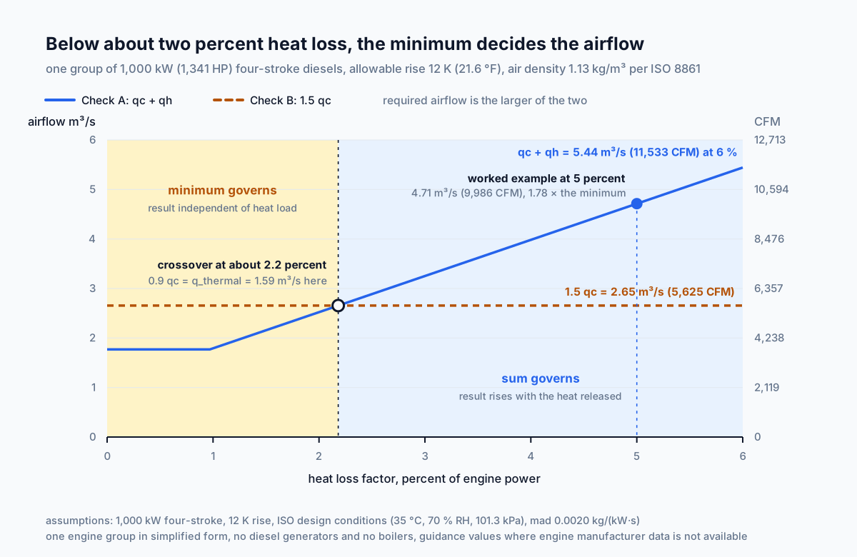
Push the heat load low enough and the arithmetic does something that looks like a fault:
Four-stroke, 1,000 kW, heat loss factor 1 percent,
rise 12.5 K (22.5 °F):

  q_thermal          = 0.7010 m³/s (1,485 CFM)
  q_thermal − 0.4 qc = 0.7010 − 0.7080
                     = −0.0070 m³/s (−15 CFM)
  qh                 = 0, taken as non-negative
  Q_required         = 2.6549 m³/s (5,625 CFM)
The negative value is not an error in the calculation. It says that the air the engines are drawing in is already removing more heat than the space is producing, so the thermal duty is met in passing and no air needs to be brought in for cooling at all. What is left is the combustion requirement and the margin the standard insists on carrying above it.
Per ISO 8861:1998 §5.1: the total airflow is the larger of the corrected sum and one and a half times the combustion air, and the second of those governs when the heat emission is low enough that the correction consumes the thermal requirement.
The Rise Is Capped at Twelve and a Half
The permitted temperature rise is not a free parameter in this calculation, because the standard sets an upper bound on it, and that bound follows from what the machinery space is expected to remain habitable and serviceable at.
Maximum rise of the machinery space air above ambient
on the design basis of the standard:

  12.5 K (22.5 °F)

With the design ambient of 35 °C (95 °F):
  machinery space design temperature 47.5 °C (117.5 °F)
Equipment in a machinery space is rated for an ambient temperature, and exceeding it shortens the service life of electronics, insulation and seals rather than stopping them outright, which is what makes the limit easy to erode. Watchkeepers have to stand watches and carry out work in the space as well, and 47.5 °C is already a demanding environment to do that in.
The pressure to erode it comes from the arithmetic. Airflow is inversely proportional to the rise, so a larger rise gives a smaller airflow, smaller fans, smaller trunks and a cheaper installation. A calculation run at a rise above the design basis of the standard still produces a number, and the number still looks like an engine room ventilation figure. What it no longer is, is a figure calculated on the basis the standard it cites is built on. The calculator flags an entry above the limit rather than silently accepting it.
When the airflow at the permitted rise comes out uncomfortably large, the levers are on the heat side rather than the temperature side. Revisit the heat emission assumption against the engine project guide, since a figure carried over from another project is often the reason. Consider the insulation of the exhaust system and the turbocharger, which is where a large part of the emission into the space originates. And check whether the vessel and its trading area call for cooling of the supply air rather than ventilation alone.
Per ISO 8861:1998 §4: the design basis limits the engine room temperature rise to 12.5 K above the design ambient, which places the design machinery space temperature at about 47.5 °C.
Two Strokes Against Four
The standard gives different combustion air values for two-stroke and four-stroke engines, and the difference carries through the whole calculation rather than affecting one term.
Four-stroke:  0.0020 kg/(kW·s)  (0.00329 lb/(HP·s))
Two-stroke:   0.0023 kg/(kW·s)  (0.00378 lb/(HP·s))

Difference: 15 percent
A two-stroke engine completes its cycle in one revolution and scavenges the cylinder with air on every cycle. Part of that scavenging air passes through the cylinder and out into the exhaust without taking part in combustion, and that pass-through is what raises the total air requirement above the four-stroke figure rather than any difference in the combustion itself.
Fifteen percent on the combustion air does not become fifteen percent on the answer:
1,000 kW, heat loss factor 5 percent, rise 12 K (21.6 °F)

  Four-stroke:  qc 1.7699, qh 2.9428, total 4.7128 m³/s
                (3,750 / 6,235 / 9,986 CFM)
  Two-stroke:   qc 2.0354, qh 2.8366, total 4.8720 m³/s
                (4,313 / 6,010 / 10,323 CFM)

Difference in the total: 3.4 percent
The reason the difference shrinks is the correction. More combustion air raises the first term of the sum and, at the same time, raises the quantity subtracted in the second, because more air is passing through the space and removing heat on the way. The two effects work against each other and most of the 15 percent cancels.
Where the engine type does move something is the boundary. The minimum sits at one and a half times a larger combustion air figure, so it is higher for a two-stroke, and control passes to it at a higher heat load: around 2.5 percent for the two-stroke against about 2.2 percent for the four-stroke.
Per ISO 8861:1998 §5.2: the guidance values for combustion air differ between two-stroke and four-stroke diesel engines, with the two-stroke figure higher because scavenging air passes through the cylinder without taking part in combustion, and both apply where engine manufacturer data is not available.
What the Simplified Model Leaves Out
The calculation covers one group of propulsion engines, and a real machinery space contains several other heat sources and air consumers the standard treats separately.
What the standard accounts for that the simplified form does not:
Diesel generators. They consume combustion air and emit heat into the space independently of the main engines, and in port they may be the only machinery running.
Boilers. They consume combustion air, which the standard accounts for on its own terms rather than inside the engine correction.
The exhaust system. It gives off heat along its entire length through the insulation, and the length involved in a machinery space is considerable.
Electrical equipment. Switchboards, transformers and frequency converters, whose losses appear in the space as heat.
Piping, tanks and heat exchangers. Every insulated hot surface in the space contributes, and there are a great many of them.
In the full form the combustion air is summed over all the diesel engines, the correction is taken against that sum, boiler combustion air is treated separately, and the heat emission is summed over all sources in the space. The simplified model computes the same relations for one engine group, so what it returns is the requirement belonging to that group.
That makes it a sound instrument for three things and a poor one for a fourth. It gives an order-of-magnitude figure at concept stage, when the machinery list is not yet fixed. It checks an existing calculation for gross error. It shows which of the two mechanisms is governing, and by how much. It is not a basis for ordering fans for a machinery space where generators and a boiler are also running.
Per ISO 8861:1998 §5 and §6: the full calculation covers propulsion engines, diesel generators and boilers as separate air consumers and sums heat emission over all sources in the machinery space, of which a single engine group is one part.
Marine Conditions the Airflow Figure Does Not Describe
An airflow figure is the same number ashore and afloat, and everything that makes marine ventilation different from building ventilation sits outside it.
Heel and trim. Fans, ducts and dampers have to keep working at the angles of heel and trim the class rules specify, static and dynamic. This is a requirement on the construction of the equipment and its mounting, and it does not change the quantity of air.
Salt-laden air. Marine air carries salt, which attacks impellers, casings and motors. Materials and coatings follow from that, and again the required airflow is unaffected.
Emergency shutdown. Machinery spaces are protected by fixed fire-extinguishing systems, and releasing the medium requires the ventilation to be stopped and the openings closed first. Damper actuators and controls are arranged outside the space so that this can be done from a position that remains accessible.
Weathertight closures. Intake trunks and openings have to stay tight when the deck is wet, which sets their height above deck and the construction of their closing appliances.
Redundancy. Rules generally require that the failure of one fan does not deprive the space of ventilation, which fixes the number of units rather than the total airflow they deliver between them.
The calculated airflow is an input to the selection of that equipment and not a solution to the ventilation problem of a machinery space. Each of the items above is set by the rules of the classification society and the flag administration concerned, and those rules are what the installation is ultimately approved against.
Per class society rules for machinery spaces and SOLAS Chapter II-2: fan construction, corrosion resistance, emergency shutdown for fixed fire-extinguishing systems, weathertight closures and redundancy are set by rules rather than by the airflow figure.
Worked Example: 1,000 Kilowatts at Five Percent
The case on the calculator page, taken through the sequence in full.
Engine power           1,000 kW (1,341 HP)
Engine type            four-stroke
Heat loss factor       5 percent (an input, not a
                         recommended value)
Allowable rise         12 °C (21.6 °F)
Step 1. Combustion airflow.
qc = 1,000 × 0.0020 / 1.13
   = 1.7699 m³/s (3,750 CFM)
Step 2. Heat emission into the space.
Φ = 1,000 × 5 / 100
  = 50 kW (170,600 BTU/h)
Step 3. Gross thermal airflow.
q_thermal = 50 / (1.13 × 1.01 × 12)
          = 50 / 13.696
          = 3.6508 m³/s (7,736 CFM)
Step 4. Heat evacuation component.
qh = 3.6508 − 0.4 × 1.7699
   = 3.6508 − 0.7080
   = 2.9428 m³/s (6,235 CFM)

The correction removes 19.4 percent of the gross
thermal airflow.
Step 5. Check A, the corrected sum.
Q1 = 1.7699 + 2.9428
   = 4.7128 m³/s (9,986 CFM)
Step 6. Check B, the mandatory minimum.
Q2 = 1.5 × 1.7699
   = 2.6549 m³/s (5,625 CFM)
Step 7. Required ventilation airflow.
Q_required = max(4.7128, 2.6549)
           = 4.7128 m³/s (9,986 CFM)
The sum governs, and the minimum sits 44 percent below it. That margin is worth recording alongside the answer, because it is what tells the next engineer that the heat assumption is carrying this result.
Step 8. Sensitivity to the temperature rise.
At the design-basis limit of 12.5 K (22.5 °F):
  q_thermal = 3.5048 m³/s (7,426 CFM)
  qh        = 2.7968 m³/s (5,926 CFM)
  Q1        = 4.5667 m³/s (9,676 CFM)

Reduction against the 12 K case: 3.1 percent
Half a kelvin of extra rise buys three percent of airflow. The heat loss factor is the sensitive input here, not the rise, which is a good reason to spend the available effort on the engine data rather than on arguing about the temperature.
Step 9. What the two rejected models would have given.
Larger of qc and q_thermal:  3.6508 m³/s (7,736 CFM)
                             22.5 percent below
Straight sum of the two:     5.4207 m³/s (11,486 CFM)
                             15.0 percent above
Step 10. What to do with the figure.
Take it as the starting airflow for fan selection, and develop the fan pressure separately from the resistance of the trunks, louvres, silencers and ducts. Confirm whether diesel generators and a boiler belong in the scope, and run the full form of the calculation if they do. And put the 5 percent heat loss factor in front of the engine manufacturer's project guide before the figure goes any further, since it alone sets the whole thermal side of the result.
The Two-Stroke Case and the Case Where the Floor Governs
Two variations on the same engine group, each showing one thing the single worked example cannot.
The first swaps the engine type and holds everything else:
1,000 kW, heat loss factor 5 percent, rise 12 °C (21.6 °F)

qc        = 1,000 × 0.0023 / 1.13
          = 2.0354 m³/s (4,313 CFM)
q_thermal = 3.6508 m³/s (7,736 CFM), unchanged
qh        = 3.6508 − 0.4 × 2.0354
          = 2.8366 m³/s (6,010 CFM)
Q1        = 2.0354 + 2.8366 = 4.8720 m³/s (10,323 CFM)
Q2        = 1.5 × 2.0354   = 3.0531 m³/s (6,469 CFM)
Required  = 4.8720 m³/s (10,323 CFM)
The combustion air is 15 percent higher and the answer is 3.4 percent higher, for the reason given earlier: the extra combustion air also removes extra heat, and the correction gives most of the difference back.
The second drops the heat load until the floor takes over:
Four-stroke, 1,000 kW, heat loss factor 1 percent,
rise 12.5 °C (22.5 °F)

qc                 = 1.7699 m³/s (3,750 CFM)
Φ                  = 10 kW (34,120 BTU/h)
q_thermal          = 10 / (1.13 × 1.01 × 12.5)
                   = 0.7010 m³/s (1,485 CFM)
q_thermal − 0.4 qc = 0.7010 − 0.7080
                   = −0.0070 m³/s (−15 CFM)
qh                 = 0
Q1                 = 1.7699 m³/s (3,750 CFM)
Q2                 = 2.6549 m³/s (5,625 CFM)
Required           = 2.6549 m³/s (5,625 CFM)
The engines in this second case are drawing in enough air to remove all the heat the space produces and a little more, so the cooling requirement disappears as a separate quantity. Without the floor the answer would be 1.7699 m³/s, which is precisely what the engines consume and therefore nothing at all for the space itself. The floor turns that into 2.6549 m³/s and keeps half the combustion air in hand.
The boundary between the two cases falls at a heat loss factor of about 2.2 percent for a four-stroke engine at a 12 K rise, and about 2.5 percent for a two-stroke at the same rise. Above it the sum governs and the result tracks the heat emission. Below it the minimum governs and the result tracks the engine power alone.
Per ISO 8861:1998 §5.1 and §5.3: at low heat emission the correction consumes the thermal requirement entirely, and the mandatory minimum of one and a half times the combustion air determines the result.
Application Boundaries: Scope, Data, Class
The scope is a machinery space ventilation calculation for a single group of diesel engines in the simplified form of the equations of the standard. Everything below needs separate treatment.
Equipment inventory. Diesel generators, boilers, the exhaust system, electrical equipment and piping are treated separately by the standard and are outside the simplified model.
Manufacturer data. The engine's stated combustion air consumption and its stated heat emission to the machinery space take precedence over the guidance values used where such data is not available.
The heat loss factor. It is entered by the user and it sets the entire thermal side of the result. Nothing in the calculation validates it.
System resistance. Trunks, louvres, silencers and ducts determine the fan pressure, which this calculation does not produce.
Air distribution. An airflow through the space does not guarantee that the air reaches the engine intakes and the hot surfaces. Short-circuiting between supply and extract satisfies the arithmetic and not the purpose.
Heel capability. Set by class rules and belonging to the construction of the equipment rather than to the airflow.
Emergency shutdown. Stopping the ventilation and closing the openings before a fixed fire-extinguishing system is released is set by rules and by the control arrangement.
Redundancy. The number of units follows from the requirement that the space keeps its ventilation when one of them fails.
Regulatory compliance. The result does not demonstrate compliance with the rules of any classification society or flag administration.
Per ISO 8861:1998 and class society rules for machinery spaces: a single engine group calculation in simplified form is the scope of this model, while equipment inventory, manufacturer data, system resistance, air distribution, heel capability, emergency shutdown and redundancy each require separate treatment.
Ship Engine Room Ventilation Calculator
Ship engine room ventilation to the structure of ISO 8861: it takes the combustion air as a mass flow per unit of engine power, converts the heat emission into a thermal airflow at the design conditions of the standard, reduces that airflow by four tenths of the combustion air because that air removes heat on its way to the engines, then compares the sum against a floor of one and a half times the combustion air. Six figures rather than one, which makes visible which check governs. A single engine group in simplified form, not a full machinery space calculation.
Open Ship Engine Room Ventilation CalculatorStandards and References
- ISO 8861:1998, Shipbuilding — Engine-room ventilation in diesel-engined ships — Design requirements and basis of calculations (International Organization for Standardization, confirmed on review in 2022 and still the current edition). The design conditions, the combustion air and heat evacuation equations, the mandatory minimum and the limit on temperature rise.
- ISO 8861:1998 §4, Design conditions (International Organization for Standardization, 1998). Ambient temperature of 35 °C at 70 percent relative humidity and 101.3 kPa atmospheric pressure, and the limit of 12.5 K on the rise of the machinery space air.
- ISO 8861:1998 §5, Air flow calculation (International Organization for Standardization, 1998). The comparison of the corrected sum against the mandatory minimum, the combustion air equation with separate values for two-stroke and four-stroke engines, and the heat evacuation equation with its correction.
- ISO 8861:1998 §6, Heat emission (International Organization for Standardization, 1998). Diesel engine heat emission as a fraction of engine power, together with the heat emission of the other equipment in a machinery space.
- SOLAS Chapter II-2, Fire protection, fire detection and fire extinction (International Maritime Organization, current consolidated edition). Requirements for category A machinery spaces, including the closing of openings and the stopping of ventilation before a fixed fire-extinguishing medium is released.
- Classification society rules for machinery spaces (current editions of the rules of the IACS member societies). Operation of machinery at specified angles of heel and trim, redundancy of ventilation fans, and the construction of air intake arrangements.
- Marine diesel engine project guides (engine manufacturers, current editions). Combustion air consumption and heat emission to the machinery space for specific engine types and ratings, which take precedence over the guidance values of the standard.
- ASHRAE Handbook, Fundamentals, chapter on psychrometrics (American Society of Heating, Refrigerating and Air-Conditioning Engineers, current edition). Moist air properties, from which the density at the design conditions of the standard is reconstructed and the volumetric heat capacity used in the thermal airflow follows.
FAQ
Does the engine room need the sum of the two airflows or the larger?
Per ISO 8861:1998 §5.1: neither exactly. The thermal airflow is first reduced by four tenths of the combustion air, since that air removes heat on its way to the engines, and the corrected sum is then compared against a floor of one and a half times the combustion air. Taking the larger of the two raw figures understates the requirement by around a fifth in the worked case, 3.6508 against 4.7128 m³/s (7,736 against 9,986 CFM).
Why is combustion air stated as a mass flow?
Per ISO 8861:1998 §5.2: because an engine needs a mass of oxygen per unit of fuel, and the volume containing that mass depends on temperature and humidity. At the design density of 1.13 kg/m³ (0.0705 lb/ft³) the same mass occupies about 6.5 percent more volume than at 20 °C (68 °F), which is the difference between temperate and tropical operation. Engine manufacturer data takes precedence over the guidance value where it is available.
What are the design conditions behind the density?
Per ISO 8861:1998 §4: an ambient temperature of 35 °C (95 °F) at 70 percent relative humidity and standard atmospheric pressure of 101.3 kPa. Those conditions describe a vessel working in the tropics rather than a temperate machinery space, and with the permitted rise of 12.5 K (22.5 °F) they put the design machinery space temperature at about 47.5 °C (117.5 °F).
When does the minimum govern instead of the sum?
Per ISO 8861:1998 §5.1: when the heat emission is low enough that the correction consumes the thermal requirement. For a four-stroke engine at a 12 K (21.6 °F) rise the crossover falls at a heat loss factor of about 2.2 percent, below which the result is one and a half times the combustion air and no longer depends on the heat load at all.
Why does the heat evacuation term come out negative sometimes?
Per the structure of the calculation: because the combustion air alone can remove more heat than the space produces. That is not an error. It means the thermal duty is met in passing, the term is taken as zero, and the mandatory minimum determines the result.
How much difference does engine type make?
Per ISO 8861:1998 §5.2: the two-stroke combustion air figure of 0.0023 kg/(kW·s) is 15 percent higher than the four-stroke 0.0020 kg/(kW·s), because scavenging air passes through the cylinder without taking part in combustion. The effect on the final airflow is smaller, around 3 percent in the worked case, since more combustion air also removes more heat and reduces the thermal term.
Is this enough for fan selection?
Per ISO 8861 and class society practice: no. The figure covers one engine group in simplified form and omits diesel generators, boilers and other heat sources the standard treats separately. Fan selection additionally needs system resistance, heel capability, corrosion resistance, emergency shutdown arrangements and redundancy, all set by class rules.
Related Calculators
- Transformer Room Ventilation: heat removal by replacement of the air in a shore-side room, where the airflow follows from the temperature difference the site makes available (article).
- Mine Ventilation Airflow: an underground working where several requirements apply at once and the governing one is the largest of them (article).
- Tunnel Ventilation Rate: two design cases carried by one set of fans (article).
- Fan Power Calculator: the power the fans absorb in delivering the calculated airflow against the resistance of trunks and louvres.
- Static Pressure Calculator: the pressure the machinery space fans have to develop, which this calculation does not produce.
- HVAC Heat Load Calculator: room heat load in the general case, where the gains are summed rather than taken as a fraction of a machine rating.
- Air Changes Per Hour Calculator: the air change rate, useful for comparison between spaces but not a basis for sizing to this standard.
- CFM Calculator: airflow in the general case, from which the sensible heat relation used on the thermal side is drawn.