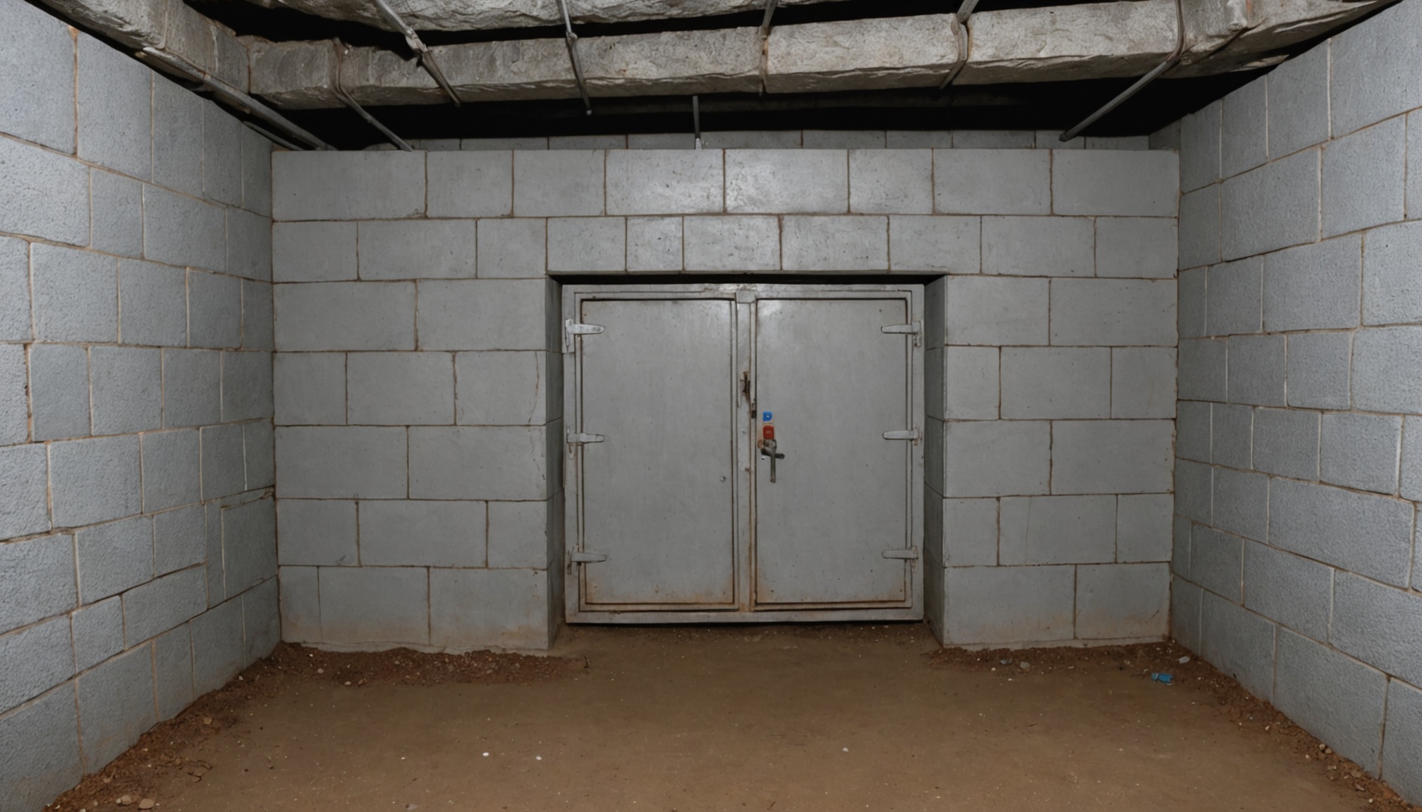
Ventilation Decides How Much a Mine Can Produce
In an underground mine the ventilation system is not a service to the operation. It is a limit on it. The quantity of air that can be delivered to a working area sets how much diesel equipment may run there, and therefore how much rock can be moved out of it.
That inverts the usual direction of the calculation. A building's ventilation follows from its occupancy and its loads: the architect fixes the space, the engineer sizes the air to suit. A mine's production follows from its ventilation. Every piece of diesel equipment underground carries a ventilation requirement with it, and a section that cannot deliver the sum of those requirements cannot run the fleet that would otherwise work there. Adding a machine means finding the air for it, and finding the air may mean a new raise, a larger fan, or a change to the mine plan itself.
Several requirements also apply at once, and they arise from unrelated sources. Diesel exhaust sets one figure. The heat rejected by equipment and by the rock itself sets another. The number of people underground sets a third. Blasting sets a fourth that is not steady at all. The governing requirement is the largest of them, and it is not always the one an engineer checks first.
The calculator normalizes a planned airflow against a duty basis and compares the result with a target intensity the user supplies. Both of those inputs carry the engineering, and neither comes from the page. This article covers where each of them comes from, why the controlling basis has to be found rather than assumed, and what happens to the air between the fan that moves it and the face that needs it. The tunnel article dealt with a single airway with traffic driving the air along it. A mine is a network with branches, dead ends and seals, in which a substantial fraction of the air never arrives where it was sent.
Calculator Inputs: Three Numbers, Two of Which Need Justifying
Two numeric fields plus a basis and a unit toggle, and the engineering sits in the two that describe the requirement rather than in the one being tested.
Unit System. Imperial (CFM) or Metric (m³/s). The airflow and the target intensity have to be stated in the same system.
Mine Ventilation Airflow [CFM or m³/s]. The planned or available airflow under test.
Ventilation Duty Basis. The quantity the airflow is normalized against. It may be a count, such as a number of diesel units or working headings, or a physical quantity, such as a heat load in kilowatts. Its dimension follows from the basis chosen, and the target intensity has to carry the same denominator.
Design Target Intensity [CFM per unit or m³/s per unit]. The airflow required per unit of that basis.
Outputs are the airflow intensity, the ratio of that intensity to the target, and a status classification.
On the dimension of the basis:
The basis is not always dimensionless. A check against a machine
count runs on a count, a check against a heat load runs on
kilowatts, and the ratio stays dimensionless only because the basis
cancels between the intensity and the target. Mixing two bases
passes the calculation and returns a classification that carries
no meaning.
What each field carries:
The airflow is the quantity under test, and it is usually known
from the ventilation plan or from the characteristic of the fan
already installed.
The basis and the target intensity together form the requirement,
and the two of them have to come from one source.
What is not among the fields:
Leakage between the fan and the point of use.
The number of requirements applying at the same time.
Network resistance and fan pressure.
The distribution of air between sections.
The absence of leakage from that list matters more than the others, and Section 10 puts a figure on it.
The Ratio Is Dimensionless and That Is What Makes It Portable
The model divides twice, and the second division removes the units entirely. That is what allows one set of interpretation bands to serve requirements as different as cubic feet per horsepower and cubic metres per kilowatt.
airflowIntensity = plannedAirflow / dutyBasis
intensityRatio   = airflowIntensity / targetIntensity
What the first division does:
It reduces the airflow to one unit of the basis. The result keeps
the dimension of a flow per unit and is comparable only with a
target expressed on the same basis.
What the second does:
It divides like by like, so the units cancel. A ratio of 1.05 means
the same thing whether the basis was counted in machines, in
kilowatts or in headings, and whichever unit system the work was
recorded in.
Why that is convenient:
One set of bands applies to every basis.
The result carries between unit systems without conversion.
Two sections with different bases can be compared at the level of
ratios, even though their absolute airflows are not comparable
quantities at all.
What it does not give:
The ratio says nothing about whether the basis was chosen correctly.
A value of 1.05 on the wrong basis looks exactly like a value of
1.05 on the right one.
The whole substance of the problem sits upstream of the arithmetic.
Per the calculator's stated model: normalizing the airflow against the duty basis and then against the target intensity produces a dimensionless ratio, which is why one set of interpretation bands applies to every basis and to both unit systems.
The Bands and What Sits Above the Recommended Range
The calculator places the ratio in one of five bands.
| Intensity ratio | Classification |
|---|---|
| below 0.75 | TOO LOW |
| 0.75 to below 0.95 | LOW / MARGINAL |
| 0.95 to 1.10 | RECOMMENDED |
| above 1.10 to 1.30 | HIGH |
| above 1.30 | TOO HIGH |
What the width of the recommended band implies:
The band from 0.95 to 1.10 is fifteen percent wide, noticeably
narrower than most scales of this kind. It reflects the fact that
underground ventilation is expensive in both directions: a
shortfall limits the work, and an excess is paid for in fan power.
Why an excess is penalised:
Fan power varies roughly with the cube of flow at a fixed network
resistance. Exceeding the requirement by thirty percent raises
consumption by 1.3 cubed, a factor of 2.2. A main mine fan runs
continuously for years, so that factor is a large number in
absolute terms.
What the bands do not account for:
The margin for leakage that has to be carried above the
requirement. An airflow referred to the main fan can look
excessive against a requirement stated at the face and still be
exactly what is needed (Section 10).
The status of the bands themselves:
The boundaries at 0.75, 0.95, 1.10 and 1.30 are the calculation's
own classification model. They are not set by any regulator, and a
ratio of 0.75 is not thereby accepted by any authority.
Acceptability follows from the applicable requirements and from
the mine's approved ventilation plan.
Per the calculator's stated bands: the recommended range of 0.95 to 1.10 is narrow because underground ventilation is costly in both directions, with a shortfall limiting production and an excess paid for continuously in fan power.
Choosing the Duty Basis Is the Whole Problem
The model is arithmetic once the basis is settled. Settling the basis is the part that requires knowing the mine.
Bases used in practice:
Diesel equipment: airflow per installed power, or per machine.
Heat load: airflow per kilowatt of heat rejected.
Personnel: airflow that dilutes contaminants to acceptable
  concentrations for a known number of people at work.
Headings: airflow per active heading.
Blasting: opening volume and a re-entry time.
Gas emission: airflow per volume of methane or radon released.
Where the target comes from in each case:
Diesel: guidance material and the engine approval (Section 7).
Heat: the allowable temperature rise of the air (Section 8).
Personnel: design criteria and the applicable requirements,
  expressed through contaminant generation and exposure limits
  rather than through any universal airflow per person.
Headings: mine practice and the nature of the work.
Blasting: the time allowed before re-entry.
Gas emission: the measured emission rate and the limiting
  concentration.
Why mixing is not permissible:
The basis and the target have to belong to the same requirement.
A machine count with a target stated per kilowatt produces a ratio
with no physical meaning, although the calculation will run and
return a classification for it.
The check on whether the pairing makes sense rests with the user.
How this looks in practice:
An engineer normally works each basis separately and collects the
results in a table by section. The calculator tests one basis at a
time, so there are as many runs as there are bases.
Per NIOSH mining ventilation guidance and standard mine ventilation practice: the ventilation requirement for a section is established separately for each applicable basis, and the duty basis and target intensity entered into any screening calculation have to belong to the same one.
Diesel: A Guidance Range Rather Than a Single Number
The figure most often quoted for diesel ventilation is not a single universal number written into a regulation. Published guidance gives a range, and the value for a particular machine follows from its engine approval and from the mine's ventilation plan.
How the requirement is structured:
Diesel engines accepted for underground use go through an approval
in which the airflow needed to dilute the exhaust to acceptable
concentrations is established for that engine. The rules require
the machine to be operated in accordance with that approval.
The guidance range:
MSHA guidance material gives airflows of roughly one hundred to
two hundred cubic feet per minute per brake horsepower of installed
power as typical practice at mines running diesel equipment. A
wider range starting near seventy five is also encountered for
metal and nonmetal mines. The figure that applies to a given
machine follows from its engine approval and from the mine's
ventilation plan.
Converting the range:
1 CFM = 0.00047195 m³/s, 1 BHP = 0.7457 kW
Compound factor: 0.00047195 / 0.7457 = 6.329e-4

100 CFM per BHP = 0.0633 m³/s per kW (63.3 m³/s per MW)
200 CFM per BHP = 0.1266 m³/s per kW (127 m³/s per MW)
What to watch in that conversion:
Both parts of the ratio have to be converted. Converting only the
numerator leaves the denominator in horsepower and understates the
figure by about a quarter.
The check runs backwards: 0.0633 x 0.7457 = 0.047, so a value of
0.047 belongs to a horsepower and not to a kilowatt.
What the target of the page example implies:
A target of 14,000 CFM per diesel unit corresponds, at one hundred
cubic feet per minute per horsepower, to a machine of roughly one
hundred and forty horsepower, and at two hundred cubic feet per
minute per horsepower to a machine of roughly seventy.
Underground loading and haulage equipment is frequently larger
than that, and a three hundred horsepower machine would carry a
requirement of thirty to sixty thousand cubic feet per minute
(14.2 to 28.3 m³/s) depending on the value taken inside the range.
Per MSHA guidance on diesel equipment ventilation and NIOSH mining research: published practice gives a range of roughly one hundred to two hundred cubic feet per minute per brake horsepower, with the value for a particular machine following from its engine approval and the mine ventilation plan rather than from a single figure in the regulation.
Heat: What a Target Intensity Implies About Temperature Rise
When the basis is heat rather than exhaust, the target intensity is not an independent choice. It follows directly from how much the air is allowed to warm on its way through the section.
The relationship:
Q = P / (ρ × c_p × ΔT)

Q   = required airflow, m³/s
P   = heat rejected, W
ρ   = air density, kg/m³, about 1.2 near surface
c_p = specific heat, 1,005 J/(kg·K)
ΔT  = allowable temperature rise of the air, K
The target intensity per kilowatt that follows from it:
target = 1,000 / (ρ × c_p × ΔT)     [m³/s per kW]

ΔT =  2 K → 0.414 m³/s per kW (878 CFM per kW)
ΔT =  3 K → 0.276 (585)
ΔT =  5 K → 0.166 (352)
ΔT = 10 K → 0.083 (176)
ΔT = 15 K → 0.055 (117)
How to use it:
The target and the allowable rise are one decision written two
ways. Choosing either one chooses the other.
The value of 0.10 m³/s per kW used in the metric example
corresponds to a rise of about eight and a half kelvin. Quoting a
target without stating the rise behind it conceals the choice that
was made.
What constrains the allowable rise:
The temperature of the air entering the section, which in a deep
mine is already elevated by compression on the way down the shaft
and by heat picked up from the rock.
The working temperature limit, which is set by a combination of
temperature and humidity rather than by dry bulb alone.
Humidity, because evaporation from wet surfaces moves part of the
heat into latent form and the dry temperature difference stops
describing the load.
What makes this harder in deep mines:
Air compresses as it descends a shaft and warms from that alone,
independently of any heat source. Rock gives up heat over the whole
service life of an opening, and the rate falls off slowly.
Both contributions arrive before any equipment starts work.
Per Hartman and McPherson on mine ventilation and air conditioning: the ventilation rate required for heat removal follows from the allowable air temperature rise through the section, so a target intensity per kilowatt and a permitted temperature rise are two statements of the same choice.
The Controlling Basis Is the Largest of Several
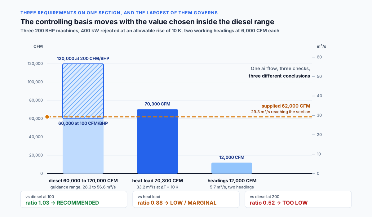
A working section is subject to every applicable requirement at once. The governing one is whichever demands the most air, and a screening calculation that checks one basis says nothing about the others.
A section worked through:
A section with three 200 BHP diesel machines, a heat load of
400 kW at an allowable rise of 10 K, and two active headings at
6,000 CFM per heading:

Diesel at 100 CFM/BHP: 3 × 200 × 100 =  60,000 CFM (28.3 m³/s)
Diesel at 200 CFM/BHP: 3 × 200 × 200 = 120,000 CFM (56.6 m³/s)
Heat: 400 / (1.2 × 1.005 × 10) = 33.2 m³/s = 70,300 CFM
Headings: 2 × 6,000 = 12,000 CFM (5.7 m³/s)
Which requirement governs:
At the bottom of the diesel range the heat basis controls, at
seventy thousand cubic feet per minute.
At the top of it the diesel basis controls, at one hundred and
twenty thousand.
A choice made inside one guidance range changes which requirement
governs the section.
What a single-basis check returns:
Airflow supplied, 62,000 CFM (29.3 m³/s):

against diesel at 100 CFM/BHP: 62,000 / 60,000  = 1.03 → RECOMMENDED
against the heat basis:        62,000 / 70,300  = 0.88 → LOW / MARGINAL
against diesel at 200 CFM/BHP: 62,000 / 120,000 = 0.52 → TOO LOW

One airflow, three checks, three different conclusions.
Which bases the example leaves out:
Personnel, gas emission and post-blast clearance are bases in their
own right, and their targets come from design criteria and the
applicable requirements rather than from any universal airflow per
unit. Where those sources matter, the number of checks rises
accordingly.
Why the order of checking matters:
An engineer who starts with the diesel basis as the most familiar
one, and takes the bottom of the range, gets a confirmation of
adequacy and stops. The controlling basis is then never examined.
The order should be the other way round: establish which
requirement is largest, then check against that one.
What moves the controlling basis:
Depth, because the heat load rises with rock temperature.
Fleet composition, because the diesel requirement is proportional
to installed power.
Work organisation, because the number of simultaneous headings and
the number of people change as mining advances. The controlling
basis is not constant over the life of a mine.
Per NIOSH mining ventilation guidance and standard practice: the ventilation requirement for a section is the largest of the applicable bases, and it changes over the life of the mine as depth, equipment fleet and working method change.
Leakage Sits Between the Fan and the Face
The airflow a fan delivers and the airflow that reaches the working face are different quantities, and in an underground network the difference is large enough to dominate the fan selection.
Where the air goes:
Through stoppings and ventilation doors separating intake from
return.
Through worked-out ground, where the resistance is lower than the
path round through the openings.
Through the joints of ventilation tubing on auxiliary duty.
Through old workings connecting parts of the network.
The order of magnitude:
The fraction that never reaches its destination commonly runs from
a third to a half of the quantity delivered in a developed network.
It grows as mining advances, because the number of available
leakage paths increases with time.
What that does to fan selection:
Requirement at the face is 60,000 CFM (28.3 m³/s) and sixty percent
of the delivered air arrives:
delivery = 60,000 / 0.60 = 100,000 CFM (47.2 m³/s)
What it does to consumption:
Fan power varies roughly with the cube of flow at a fixed network:
(100,000 / 60,000)³ = 4.6
A forty percent leakage multiplies main fan consumption by nearly
five against the same airflow delivered to the face without loss.
Why sealing pays:
The cost of sealing stoppings and maintaining ventilation
structures is a small fraction of the energy cost it avoids. The
cubic relationship means a ten percent reduction in leakage
returns considerably more than a ten percent reduction obtained
any other way.
What to do with the calculation:
The value entered has to belong to the point in the network being
checked. Airflow at the main fan is checked against a requirement
that includes leakage, airflow at the face against one that does
not.
Mixing the two points overstates adequacy.
Per McPherson on subsurface ventilation engineering and NIOSH guidance: leakage through stoppings, worked-out areas and duct connections commonly accounts for a third to a half of the air a main fan delivers, and because fan power varies with the cube of flow, that leakage multiplies the energy required several times over.
Recirculation Is Forbidden Above Ground and Sometimes Deliberate Below
Returning contaminated air to a workplace is excluded by principle in building ventilation. In underground mining it is a recognised technique applied under controlled conditions.
Why buildings exclude it:
Recirculation returns contaminants to the space, and ventilation
requirements are written in terms of outdoor air supply precisely
so that this does not happen.
Why underground is different:
Fresh air has to be carried long distances through openings with
substantial resistance, and the cost of delivering it rises with
depth and with the extent of the network.
Controlled recirculation raises the air velocity in a working place
without raising the quantity brought down from surface.
The conditions attached to it:
Continuous monitoring of concentrations with automatic shutdown on
exceedance. Sufficient dilution with fresh air that the steady
concentration stays below the limit. Absence of sources for which
dilution does not work in principle. Whether it is permitted at
all, and on what conditions, is set by the jurisdiction and
differs between countries.
What it changes for the calculation:
Under recirculation the flow through the opening and the fresh air
quantity stop being the same number. The dilution requirement
applies to the fresh air, while the velocity and heat removal
requirements apply to the total flow.
One figure is no longer enough to check both.
Per NIOSH mining research and international mine ventilation practice: controlled recirculation is applied underground under continuous monitoring, unlike building ventilation where returning contaminated air to an occupied space is excluded by principle.
Natural Ventilation Pressure Changes Sign With the Season
A mine with openings at different elevations develops a pressure difference from the density contrast between the air inside and the air outside. That pressure works with the fans in one season and against them in another.
Where it comes from:
Δp = (ρ_out − ρ_in) × g × H

H = elevation difference between the openings, m
ρ = air density, kg/m³
g = 9.81 m/s²
The order of magnitude:
With an elevation difference of three hundred metres (984 ft), an
outside density of 1.25 kg/m³ in winter and an inside density of
1.15 kg/m³:
  Δp = 0.10 × 9.81 × 300 = 294 Pa (1.18 in w.g.)
Against the fan:
A main mine fan develops something in the order of one to three
thousand pascals (4 to 12 in w.g.). The natural pressure above is
ten to thirty percent of that, enough to shift the distribution of
air through the network appreciably.
The change of sign:
In winter the outside air is colder and denser than the air inside
and the draught runs one way. In summer the relationship reverses
and the draught runs the other. In the transitional periods it
passes through zero, and that is when the ventilation is least
stable.
What is done about it:
The network is solved for several seasonal states rather than one.
The direction of the main airflows is chosen so that the natural
pressure assists during the season that is hardest to ventilate.
Stability is checked for the case in which it opposes the fans.
Per McPherson on subsurface ventilation engineering: the density difference between intake and return air develops a natural ventilation pressure that varies seasonally and reverses direction, and network calculations are carried out for several seasonal states rather than one.
Blasting Is a Batch Problem Inside a Steady Model
Most ventilation requirements are steady. The one produced by blasting is not: a fixed quantity of gas is released at a moment in time, and the requirement is a clearance time rather than a dilution rate.
The problem as posed:
A blast releases a certain volume of gases into the volume of the
opening. The requirement is that the concentration fall to a safe
level within the time allowed, after which people may re-enter.
An approximate clearance time:
Under complete mixing the concentration decays exponentially with
a time constant equal to the volume of the opening divided by the
airflow.

τ = V / Q

An opening of ten thousand cubic metres (353,000 ft³) at an airflow
of twenty cubic metres per second (42,400 CFM):
  τ = 10,000 / 20 = 500 s = 8.3 minutes
A twenty-fold reduction takes about three τ, on the order of
twenty-five minutes.
Why the approximation is coarse:
Mixing in a dead-end heading is far from complete, and stagnant
zones clear considerably more slowly than the calculation
suggests. On auxiliary ventilation by tubing the picture depends on
the distance from the end of the tube to the face and on the mode
of delivery.
What that means for a steady-state check:
The post-blast requirement is not expressed as an airflow per unit
of basis and does not fit the model. It is checked separately, and
it can be the controlling one in development headings, where few
other continuous sources exist.
Per NIOSH mining guidance and mine ventilation practice: clearance of blasting fumes is a transient problem in which a fixed quantity of gas decays with a time constant set by the ratio of opening volume to airflow, and incomplete mixing in a heading makes the actual clearance time longer than that estimate.
Worked Example: 42,000 CFM Across Three Diesel Units
The scenario matches the Imperial example on the calculator page.
Airflow 42,000 CFM (19.8 m³/s)
Basis three diesel units
Target intensity 14,000 CFM per unit (6.61 m³/s per unit)
Step 1. Airflow intensity.
airflowIntensity = 42,000 / 3 = 14,000 CFM per unit (6.61 m³/s)
Step 2. Ratio to the target.
intensityRatio = 14,000 / 14,000 = 1.00
Step 3. Classification.
1.00 falls inside the band from 0.95 to 1.10 → RECOMMENDED
Step 4. What machine the target corresponds to.
At one hundred cubic feet per minute per horsepower, a target of
14,000 CFM corresponds to about one hundred and forty horsepower
of installed power per unit. At two hundred cubic feet per minute
per horsepower the same target corresponds to a machine of about
seventy. A three hundred horsepower machine would carry a
requirement of thirty to sixty thousand cubic feet per minute
(14.2 to 28.3 m³/s), depending on the value taken inside the range.
Step 5. The same check in metric.
42,000 CFM × 0.00047195 = 19.82 m³/s
14,000 CFM per unit = 6.61 m³/s per unit
19.82 / 3 = 6.61 m³/s per unit, the same ratio of 1.00
The ratio is dimensionless and does not depend on the unit system.
Step 6. What the check does not cover.
The result belongs to the diesel basis and to that basis alone, at
one chosen value inside the guidance range. Heat load, heading
count and the remaining bases are checked separately, and any of
them may be higher.
Step 7. The point in the network the airflow belongs to.
If 42,000 CFM refers to main fan delivery rather than to the air at
the machines, then at thirty percent leakage about 29,400 CFM
(13.9 m³/s) arrives, which gives an intensity of 9,800 CFM per unit
(4.63 m³/s) and a ratio of 0.70, a classification of TOO LOW.
Step 8. What a ratio of exactly 1.00 means.
An exact match with the target means no margin at all. Any
deterioration, whether fan wear, rising network resistance or added
equipment, moves the section into the band below.
Step 9. What one more machine does.
A fourth machine at the same airflow gives
42,000 / 4 = 10,500 CFM per unit (4.96 m³/s) and a ratio of 0.75,
the bottom edge of the LOW / MARGINAL band.
This is the mechanism by which ventilation limits the fleet on a
section.
Step 10. What to do next.
Establish the controlling basis among all those that apply.
Establish which point in the network the tested airflow belongs to.
Carry a margin for leakage when moving from a requirement at the
face to a delivery at the fan.
Metric Example and a Controlling Basis Check
The scenario matches the Metric example on the calculator page.
Airflow 18.9 m³/s (40,050 CFM)
Basis 180 kW of heat load
Target intensity 0.10 m³/s per kW

airflowIntensity = 18.9 / 180 = 0.105 m³/s per kW (223 CFM per kW)
intensityRatio = 0.105 / 0.10 = 1.05 → RECOMMENDED
A note on the dimension of the basis:
Here the basis has the dimension of power rather than being a
count. The ratio stays dimensionless because the kilowatts cancel
between the intensity and the target.
What temperature rise that target corresponds to:
target = 1,000 / (ρ × c_p × ΔT)
0.10 = 1,000 / (1.2 × 1,005 × ΔT)
ΔT = 1,000 / (1.2 × 1,005 × 0.10) = 8.3 K (14.9 °F)
Choosing a target of 0.10 is therefore choosing a rise of a little over eight kelvin.
What a different allowable rise would give:
ΔT =  5 K → target 0.166 m³/s per kW, 29.9 m³/s (63,350 CFM) required
ΔT = 10 K → target 0.083, 14.9 m³/s (31,570 CFM) required
ΔT = 15 K → target 0.055,  9.9 m³/s (20,980 CFM) required
At an allowable rise of five kelvin the supplied 18.9 m³/s gives a ratio of 0.63 and a classification of TOO LOW.
A check on a second basis:
If the same section serves two diesel machines of one hundred and
fifty horsepower each:

at 100 CFM/BHP: 2 × 150 × 100 = 30,000 CFM = 14.2 m³/s
at 200 CFM/BHP: 2 × 150 × 200 = 60,000 CFM = 28.3 m³/s

The supplied 18.9 m³/s gives a ratio of 1.33 against the bottom of
the range, TOO HIGH, and 0.67 against the top, TOO LOW.
One basis at one airflow returns opposite conclusions depending on
the value taken inside the guidance range.
What the comparison shows:
The same quantity of air is classified anywhere from TOO LOW to
TOO HIGH depending on which basis is taken as controlling, what
temperature rise is allowed, and what value is chosen inside the
guidance range.
The magnitude of the ratio carries no indication of whether those
choices were made correctly.
Per Hartman and McPherson: the target intensity for heat removal and the allowable temperature rise are two forms of the same decision, so a target of 0.10 m³/s per kW corresponds to a rise of about 8.3 K, and a stricter limit raises the requirement in proportion.
Application Boundaries: Networks, Pressure, Compliance
The model normalizes a stated airflow against one basis and compares the result with a target the user supplies. The following sit outside it and need separate treatment.
Choice of controlling basis. The calculation checks the basis entered and does not report whether a more demanding one exists.
The value taken inside a guidance range. For the diesel basis, published practice gives a range rather than a single figure, and the choice inside it changes the conclusion.
Leakage. The difference between air delivered and air arriving is not modelled, and in a developed network it is a large fraction of the total.
Network solution. The distribution of air between sections follows from branch resistances and regulating devices, and is found by solving the network rather than by dividing.
Pressure and resistance. Fan selection needs a network characteristic, which this calculation does not produce.
Natural ventilation pressure. A seasonally varying pressure affects the distribution and is not part of the model.
Recirculation. Where it is applied, the flow through the opening and the fresh air quantity differ, and one figure stops describing both requirements.
Transient conditions. Clearance after blasting is an unsteady problem and is not expressed through an airflow per unit of basis.
Concentration distribution. An adequate total airflow does not guarantee the absence of local accumulation in stagnant zones.
Regulatory compliance. The result does not demonstrate compliance with MSHA requirements or those of any other jurisdiction and does not replace ventilation plan documentation. The classification bands are not set by any regulator.
Per MSHA Part 57 requirements and NIOSH mining guidance: normalizing a stated airflow against a single duty basis is the scope of this model, while basis selection, leakage, network solution, fan pressure, natural ventilation pressure, transient clearance and regulatory compliance require dedicated analysis.
Mine Ventilation Airflow Calculator
Mine ventilation airflow against a duty basis: it divides the planned airflow by the duty basis to give an airflow intensity, then divides that by the target intensity for a dimensionless ratio, and places the ratio in a band from too low to too high. Both the basis and the target come from the user, and the engineering sits in choosing them: the governing requirement is the largest of several that apply at once, and the airflow a fan delivers is not the airflow that reaches the face. A screening check on one basis, not a ventilation design.
Open Mine Ventilation Airflow CalculatorStandards and References
- MSHA 30 CFR Part 57, Safety and Health Standards for Underground Metal and Nonmetal Mines (Code of Federal Regulations, Title 30, revised annually). Requirements covering ventilation, the use of diesel equipment and the control of exposure to airborne contaminants. The applicable provision depends on the type of mine and the jurisdiction.
- MSHA 30 CFR Part 75, Mandatory Safety Standards for Underground Coal Mines (Code of Federal Regulations, Title 30, revised annually). Requirements for coal mines, which differ from those applying to metal and nonmetal mines and are written against different hazards.
- MSHA, Practical Ways to Reduce Exposure to Diesel Exhaust in Mining: A Toolbox (1997). Guidance describing typical airflows supplied per unit of installed diesel power at mines running diesel equipment, and the control measures that go with them.
- MSHA, diesel particulate matter rules for underground metal and nonmetal mines (Federal Register, 2001, as subsequently amended). The regulatory background against which engine approvals and mine ventilation plans for diesel equipment are written.
- NIOSH Mining Program, ventilation research and guidance (continuing programme). Recommendations on diluting diesel emissions, on leakage, and on the planning of ventilation for underground openings.
- NIOSH Mining Program, Air Quantity Estimator (AQE). A tool for estimating the air quantity needed to dilute diesel particulate matter in large-opening underground mines.
- NIOSH, Handbook for Dust Control in Mining, IC 9465 (2003). Control of airborne dust at the source underground, as a complement to dilution by ventilation.
- Hartman, H. L., Mutmansky, J. M., Ramani, R. V., Wang, Y. J., Mine Ventilation and Air Conditioning, 3rd edition (Wiley, 1997). The standard course text on underground ventilation, heat loads and the air conditioning of mine air.
- McPherson, M. J., Subsurface Ventilation and Environmental Engineering (Chapman & Hall, 1993). Network solution, leakage, natural ventilation pressure, heat exchange with the rock mass, and controlled recirculation.
- ACGIH, Threshold Limit Values and Biological Exposure Indices (revised annually, 2026 edition). Exposure limits for airborne contaminants, against which dilution requirements are written.
- Fan and ventilation tubing manufacturer data (current published catalogue data). Fan characteristics, tubing leakage coefficients and installation requirements.
FAQ
How is mine ventilation airflow evaluated against a requirement?
Per standard mine ventilation practice: by normalizing the airflow against the duty basis to give an intensity per unit, then dividing that by the target intensity for the same basis. The ratio is dimensionless, so one set of bands applies whether the basis is diesel units, kilowatts of heat, or headings.
What ventilation rate does diesel equipment need?
Per MSHA guidance on diesel equipment ventilation: published practice gives a range of roughly 100 to 200 CFM per brake horsepower, which converts to 0.063 to 0.127 m³/s per kW once both parts of the ratio are converted. The value for a particular machine follows from its engine approval and the mine ventilation plan rather than from a single figure.
How does a heat removal target relate to temperature rise?
Per Hartman and McPherson: they are the same choice written two ways. The target follows from 1,000 divided by the product of air density, specific heat and the allowable rise, so 0.10 m³/s per kW corresponds to a rise of about 8.3 K and 0.166 to a rise of 5 K.
Which ventilation requirement governs a working section?
Per NIOSH mining guidance: the largest of those that apply. Diesel exhaust, heat removal, heading demand and contaminant dilution each produce a figure, and the governing requirement is the highest of them. Checking one basis alone can return an adequate result while a larger requirement goes unexamined.
How much air is lost to leakage?
Per McPherson on subsurface ventilation: commonly a third to a half of what a main fan delivers, through stoppings, worked-out areas and duct connections. Because fan power varies with the cube of flow, a forty percent loss multiplies the energy required by roughly five against the same airflow delivered without loss.
Why is recirculation used underground when buildings forbid it?
Per NIOSH mining research and international practice: because delivering fresh air over long distances underground is expensive, and controlled recirculation raises air velocity in a working place without raising the quantity brought from surface. It is applied under continuous monitoring, with conditions set by the jurisdiction.
Does a recommended result mean the section is adequately ventilated?
Per MSHA requirements and mine ventilation practice: no. The result applies to the basis entered, at the point in the network the airflow refers to, and under an assumption of complete mixing. Leakage, the choice of controlling basis, local accumulation and transient conditions after blasting all sit outside it. The classification bands are the calculator's own screening model rather than a regulatory threshold.
Related Calculators
- Tunnel Ventilation Rate: an underground opening with a single air path, where the traffic itself produces part of the air movement (article).
- Parking Garage CO Ventilation: dilution of exhaust in an enclosed volume, where the same logic of normalizing against a source comes from (article).
- Fan Power Calculator: the main fan power that rises with the cube of flow, which is what makes leakage so expensive.
- Static Pressure Calculator: the pressure a fan has to develop against network resistance and against natural ventilation pressure.
- Duct Friction Loss Calculator: losses along ventilation tubing on auxiliary duty at a heading.
- Air Changes Per Hour Calculator: the exchange rate that sets the time constant of an opening during clearance after a blast.
- Dust Collection System Sizing: capture of dust at the source, as a complement to dilution.
- HVAC Heat Load Calculator: the heat load that in deep mines frequently turns out to be the controlling basis.