The Room Is Cooled by Replacement, Not by Refrigeration
A cooling coil can hold a room at any temperature the plant behind it can reach. Ventilation cannot. It can only bring a room down towards the temperature of the air entering it, and the closer those two temperatures get, the more air the work takes. What governs a ventilated transformer room is therefore not the heat to be removed but the temperature rise permitted between the entering air and the air the equipment sees, and that rise is set by the site at least as much as by the equipment.
That bounds the design with something no equipment selection can move. A larger fan raises the airflow through the room. It does nothing to the temperature difference that carries the heat, and as that difference approaches zero the airflow required approaches infinity. A room on a temperate site and the same room on a hot site, holding the same transformer at the same load, are not variations of one problem by a few percent. They can differ by an order of magnitude in the air they need, without a single figure changing on the equipment side.
The room also has no occupants to satisfy and no setpoint to hold. It has a piece of equipment whose insulation ages faster as its temperature climbs, and the airflow exists to keep the air arriving at that equipment below a stated limit. Comfort ventilation answers to people, who notice immediately when it is wrong. This answers to an insulation system with a temperature-dependent service life, which does not notice at all until years later.
The calculator divides a heat loss by a temperature rise and a constant, and returns an airflow. Two fields, one division, and both fields routinely receive the wrong quantity. The heat loss field attracts the transformer's rating rather than its losses, an error that overstates the result by a factor of tens and announces itself on sight. The temperature rise field attracts the winding temperature rise from the nameplate rather than the permitted rise of the room air, an error that understates the result by a factor of ten or more and returns a figure that looks entirely reasonable. What follows covers both quantities, where each of them properly comes from, and why the choice between natural and mechanical ventilation turns on the temperature rise rather than on the airflow it produces.
Calculator Inputs: A Heat Loss and a Temperature Rise
Two numeric fields and a unit toggle. Each numeric field has a near-twin in the documentation of the transformer it describes, and that is the whole difficulty of the page.
Unit System. Imperial (BTU/h, °F, CFM) or Metric (kW, °C, m³/h). The category thresholds convert between the two, so a given airflow keeps its band when the toggle moves.
Transformer Heat Loss [BTU/h or kW]. The heat the transformer rejects into the room air at the operating condition being evaluated. It comes from the test report or the datasheet, not from the nameplate rating, which is a different quantity larger by a factor of tens.
Allowable Temperature Rise [°F or °C]. The permitted rise of the room air above the ventilation air entering the room. This is not the winding temperature rise printed on the transformer nameplate, and the two differ by more than an order of magnitude.
The outputs are the required ventilation rate, the same airflow converted, and a result category.
The relation itself:
Imperial: CFM  = Heat Loss [BTU/h] / (1.08 × ΔT [°F])
Metric:   m³/s = Heat Loss [W] / (1200 × ΔT [°C])
          m³/h = m³/s × 3600

Heat Loss  heat rejected to the room air
             single-figure kilowatts for a distribution
             transformer, tens for a large unit
ΔT         allowable rise of the room air
             typically single-figure kelvins, set by the
             site and the equipment together
1.08       imperial sensible heat constant
             = 60 × 0.075 × 0.24
1200       metric sensible heat constant
             a rounding of 1.2 × 1005 = 1206
The airflow is inversely proportional to the allowable rise, and that single property drives most of what follows:
Half the rise means twice the air.
A fifth of the rise means five times the air.
No other quantity in this problem carries
that sensitivity.
The result categories, as published on the page:
LOW         below 2,000 CFM        below 3,398 m³/h
MODERATE    2,000 to 5,000 CFM     3,398 to 8,495 m³/h
HIGH        5,000 to 10,000 CFM    8,495 to 16,990 m³/h
VERY HIGH   above 10,000 CFM       above 16,990 m³/h

The metric cuts are the imperial cuts converted at
1 CFM = 1.699 m³/h, so one airflow keeps one band
in either unit system.
What is not among the fields matters as much as what is:
The temperature of the entering air, which the rise
  is measured from.
The vertical separation between the intake and exhaust
  openings, which sets the natural draught.
The path the air takes through the room.
The load on the transformer, which the losses depend on.
Two Quantities Called Temperature Rise
The documentation of a transformer and the input field of this calculation both use the phrase temperature rise. They refer to different things, and the numbers differ by more than an order of magnitude.
Winding temperature rise
  How much hotter the winding runs than the air around
  it at rated load. A property of the transformer and
  its insulation system. Values in the region of 80,
  115 and 150 °C (144, 207 and 270 °F) appear on the
  nameplates of dry-type units.

Allowable room air temperature rise
  How much warmer the room air may become than the air
  entering the room. A property of the site and of the
  inlet temperature the equipment permits. Values are
  normally single-figure kelvins.
The confusion has four supports at once. Both quantities are called a temperature rise. Both are expressed in degrees. Both belong to the documentation of the same machine. And the first of them is printed on the nameplate, so it is the one that comes to hand first.
Substituting the first for the second, at a loss of 10.2 kW (34,800 BTU/h) with air entering at 30 °C (86 °F) against a permitted inlet temperature of 40 °C (104 °F), which is an allowable rise of 10 K (18 °F):
Correct:
  Q = 10,200 / (1200 × 10)   = 0.850 m³/s
                             = 3,060 m³/h (1,801 CFM)

Winding rise of 150 substituted for the allowable
rise of 10:
  Q = 10,200 / (1200 × 150)  = 0.0567 m³/s
                             =   204 m³/h (120 CFM)

Ratio: 15 times.
This error is more dangerous than the one in the other field, and the reason is the appearance of the result rather than its size. Putting the nameplate rating into the heat loss field overstates the airflow by a factor of tens and produces a figure that is absurd for a room of that size. Putting the winding rise into the temperature field understates it, and 204 m³/h (120 CFM) for a transformer room looks modest and plausible. Both the correct 3,060 m³/h and the mistaken 204 m³/h fall in the LOW band, so the category offers no signal that anything is wrong. The room is then built with a fifteenth of the ventilation it needs, and nothing in the calculation objects.
The two quantities are related, which is why one can stand in for the other without looking foolish. The temperature of the winding is the temperature of the air at the transformer inlet plus the rise of the winding above it, plus the excess of the hottest spot over the average winding. The allowable rise of the room air exists precisely so the first of those terms stays inside the bounds where the sum remains within the rated temperature of the insulation system. Related, and not interchangeable.
Per IEEE C57.12.01 and manufacturer installation guidance for dry-type transformers: winding temperature rise classes describe how much hotter the winding runs than the air around it, while the allowable rise in this calculation describes how much hotter the room air may become than the air entering the room, and the two differ by more than an order of magnitude.
Where the Allowable Rise Actually Comes From
The allowable rise is not chosen. It is what remains after two other temperatures have been established, one by the equipment and one by the site.
ΔT_allowable = T_inlet_limit − T_entering_air

T_inlet_limit    maximum air temperature the transformer
                   permits at its inlets, from the
                   manufacturer's installation guidance
T_entering_air   temperature of the ventilation air
                   arriving in the room
The second of those has more than one source:
Ventilating with outdoor air: the site summer design
  temperature.
Drawing from an adjacent space: the temperature of that
  space.
Supplied through an air handling system: the supply air
  temperature of that system.

Outdoor air is the common case rather than the only one.
Two consequences follow. The allowable rise is a site quantity as much as an equipment quantity, and the same transformer in a temperate and in a hot climate requires substantially different airflow with its losses unchanged. Against a 40 °C (104 °F) inlet limit:
Entering air 20 °C (68 °F):     rise 20 K, base case
Entering air 30 °C (86 °F):     rise 10 K, twice the air
Entering air 35 °C (95 °F):     rise  5 K, four times
Entering air 38 °C (100.4 °F):  rise  2 K, ten times
Entering air 40 °C (104 °F):    no rise at all, and
                                  outdoor air ventilation
                                  does not solve the problem
When the rise runs out, more air stops being the answer, because the rise falls towards zero faster than the airflow can be raised. What remains is to lower the temperature of the entering air by drawing it from a conditioned volume or cooling it, to lower the heat by limiting the load on the transformer, or to select equipment with a higher permitted inlet temperature where that is available.
This is also why the field should not be filled in by preference. Both of the temperatures behind it are documented, one by the manufacturer and one by the climatic data for the site. A rise assumed without reference to them carries a silent assumption about the inlet temperature that may not hold on the day it matters.
Per manufacturer installation guidance for dry-type transformers and site design temperature data: the allowable rise of the room air is the difference between the maximum inlet air temperature the transformer permits and the temperature of the air entering the room, so it follows from the site as much as from the equipment.
Heat Loss Is Not the Nameplate Rating
The first field asks for the heat the transformer rejects into the room. The number most readily to hand is its rating, which describes a different thing and is larger by a factor of tens.
What the field wants
  The heat delivered to the room air, that is the total
  loss of the transformer at the operating condition
  under consideration.

What the nameplate offers
  The rated apparent power, that is the power passing
  through the transformer rather than the power lost
  inside it.
The scale of the difference, as a worked illustration rather than a typical value:
A 500 kVA transformer, assumed to run at an efficiency
of about 98 percent at unity power factor:

  P_loss = 500 × (1/0.98 − 1) = 10.2 kW (34,800 BTU/h)

Substituting 500 for 10.2 overstates the airflow
by a factor of 49.
That error is self-announcing. At an allowable rise of 10 K (18 °F) it returns 150,000 m³/h (88,300 CFM) instead of 3,060 m³/h (1,801 CFM). An airflow of that order for an electrical room is absurd on sight, and the result lands in the VERY HIGH band, three bands away from where the correct figure sits.
The losses themselves come from the manufacturer's test report or datasheet, where no-load and load losses are stated separately. Where only a declared efficiency is available, the total loss can be derived at the operating point and power factor for which that efficiency is stated. A declared efficiency does not necessarily refer to full load, and treating it as a full-load figure without checking introduces an error in the loss before the airflow calculation begins.
Knowing the two loss components separately matters beyond the arithmetic above. No-load losses stay approximately constant while load losses vary approximately with the square of load current, so restating the heat at an actual load factor needs both components. A single total is not enough to do it.
Per manufacturer test reports and datasheets for dry-type transformers: the heat rejected to the room is the total loss at the operating condition under consideration, taken from test data that reports no-load and load losses separately, rather than the apparent power rating.
Losses Do Not Scale With Load
Half load does not mean half the heat. One part of the loss does not change with load at all, and the other changes with its square.
P_loss(k) = P_no-load + P_load × k²

P_no-load   no-load loss, approximately constant,
              from magnetisation of the core, kW
P_load      load loss at rated load, from current in
              the windings, kW
k           fraction of rated load, 0 to 1 and above
Taking the 10.2 kW (34,800 BTU/h) full-load figure from the previous section and splitting it 30 percent constant and 70 percent load-dependent, again as an illustration rather than as a typical division:
  P_no-load = 3.06 kW,  P_load = 7.14 kW

  k = 1.00:  3.06 + 7.14 × 1.000 = 10.20 kW  (100%)
  k = 0.75:  3.06 + 7.14 × 0.563 =  7.08 kW  ( 69%)
  k = 0.50:  3.06 + 7.14 × 0.250 =  4.85 kW  ( 48%)
  k = 0.25:  3.06 + 7.14 × 0.063 =  3.51 kW  ( 34%)
  k = 0:     3.06                =  3.06 kW  ( 30%)

The 30/70 split is assumed for the illustration.
The actual division differs between designs and is
read from the manufacturer's data.
The shape of that column is the point. At half load the heat is 48 percent of the full-load figure rather than 50, which is a small difference. At a quarter load it is 34 percent rather than 25, which is not. And with no load at all the transformer still rejects most of a third of its full-load heat, because the core is still magnetised.
Three practical consequences follow. The room needs ventilation with the load disconnected, since the no-load component does not go away. Sizing on full-load losses is conservative for a unit that runs persistently underloaded, but the saving available is smaller than the load fraction suggests. And restating the heat at an actual load factor requires the two components separately, which returns the question to the test report.
Per IEEE C57.96 and transformer loading practice: no-load losses remain approximately constant while load losses vary approximately with the square of load current, so heat rejection at partial load is a larger fraction of the full-load figure than the load fraction itself.
Natural Ventilation Fails Twice as the Rise Shrinks
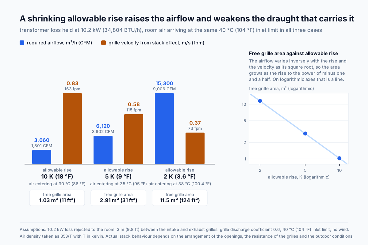
A shrinking allowable rise raises the airflow required and lowers the pressure available to deliver it at the same time. The grille area needed therefore grows faster than the airflow does, and natural ventilation stops being practical well before the airflow figure alone would suggest.
The driving pressure comes from the density difference between the two columns of air:
Δp = (ρ_entering − ρ_room) × g × h

h   vertical separation between the intake and exhaust
      grilles, m
ρ   air density, kg/m³, approximately 353/T with T in
      kelvin
g   9.81 m/s²
And the velocity that pressure produces through an opening:
v = C_d × sqrt(2 Δp / ρ)

C_d   grille discharge coefficient, taken as 0.6 here
Worked through at a loss of 10.2 kW (34,800 BTU/h), a permitted inlet temperature of 40 °C (104 °F) and 3 m (9.8 ft) between the grilles:
Entering air 30 °C (86 °F), rise 10 K (18 °F):
  Δρ = 1.1644 − 1.1272 = 0.0372 kg/m³
  Δp = 0.0372 × 9.81 × 3 = 1.09 Pa (0.0044 in w.g.)
  v  = 0.6 × sqrt(2 × 1.09 / 1.146)
     = 0.83 m/s (163 fpm)
  Q  = 3,060 m³/h (1,801 CFM) = 0.850 m³/s
  A  = 0.850 / 0.829 = 1.03 m² (11.0 ft²) free area

Entering air 35 °C (95 °F), rise 5 K (9 °F):
  Δp = 0.54 Pa, v = 0.58 m/s (115 fpm)
  Q  = 6,120 m³/h (3,602 CFM) = 1.700 m³/s
  A  = 2.91 m² (31.3 ft²)

Entering air 38 °C (100.4 °F), rise 2 K (3.6 °F):
  Δp = 0.21 Pa, v = 0.37 m/s (73 fpm)
  Q  = 15,300 m³/h (9,006 CFM) = 4.250 m³/s
  A  = 11.5 m² (124 ft²)
The exponent behind those three lines is worth stating, because it is what makes the last one so much worse than the first. The airflow varies inversely with the rise. The stack pressure varies in proportion to the rise, so the velocity varies as its square root. The area, being the ratio of the two, varies as the rise to the power of minus one and a half:
(10/5)^1.5 = 2.83  against an area ratio of 2.84
(10/2)^1.5 = 11.18 against an area ratio of 11.25
What those areas mean once they leave the arithmetic:
Free area is commonly around half of the overall size
of a grille, so the three cases correspond to openings
of roughly 2, 6 and 23 m² (22, 63 and 250 ft²) at each
of the two positions.

The last of those exceeds what fits on the wall of an
ordinary electrical room.
The calculation above assumes the discharge coefficient, the separation and the absence of wind stated with it. Actual stack behaviour depends on the arrangement of the openings, the resistance of the grilles chosen and the outdoor conditions on the day.
Per natural ventilation practice and manufacturer guidance on transformer room openings: the stack pressure available scales with the temperature difference while the airflow required scales inversely with it, so the free grille area needed grows faster than the airflow and natural ventilation ceases to be practical before the airflow figure alone would suggest.
The Two Constants Are Not Exact Equivalents
The imperial and metric forms of the same relation use constants that are not exact equivalents, so equivalent inputs return results that differ by about half a percent.
Imperial: 1.08 = 60 min/h × 0.075 lb/ft³
                 × 0.24 BTU/(lb·°F)
Metric:   1200 ≈ 1.2 kg/m³ × 1005 J/(kg·K) = 1206
Converting the imperial constant into SI units settles where the difference comes from:
1.08 BTU/(h·CFM·°F)
  = 1.08 × 0.293071 W / (0.000471947 m³/s × 5/9 K)
  = 1,207 W·s/(m³·K)

Against the metric 1,200: a difference of 0.6 percent.
It shows up in the two examples on the page. The imperial one returns 1,111 CFM. The metric one, from equivalent inputs, returns 1,900 m³/h, which is 1,118 CFM. The ratio is 1.006, the same 0.6 percent.
It does not come from the unit conversion. The factor between CFM and m³/h is known to five decimal places, and rounding it contributes an error in the hundredths of a percent. The six tenths of a percent observed comes from the constants themselves.
Nothing needs to be done about it. Both constants are established in practice, and the gap between them is small against the uncertainty in the inputs, where losses are known to within a few percent and the design outdoor temperature to within a degree. One habit is worth keeping: do not compare results taken in different unit systems and expect the last digit to agree.
Per the derivation of the two constants: the imperial 1.08 corresponds to about 1,207 in SI units while the metric form uses 1,200, a rounding of the product 1.2 × 1005, and the resulting difference of about 0.6 percent is small against the uncertainty of the inputs.
Air That Reaches the Grille but Not the Transformer
The calculation gives the air that has to pass through the room. Whether that air passes over the transformer is a question about where the openings are, and it is not asked anywhere on the page.
Where the intake and exhaust openings sit close together
on the same wall, part of the flow travels straight from
one to the other without entering the volume of the room.

The airflow measured at the grilles matches the design
figure. The air around the transformer turns over more
slowly than it should.
The arrangement that avoids this is the one that also produces the most draught:
Intake low, exhaust high on the opposite side, so the
flow crosses the volume of the room and the zone where
the transformer gives up its heat.

That arrangement gives the greatest vertical separation
at the same time, and therefore the greatest stack
pressure.
A short-circuited room is difficult to detect by the obvious measurement. Airflow at the grille reads the design value. The air temperature at the transformer inlet sits above the calculated figure, because a smaller share of the flow reaches it than the calculation assumed. Checking the airflow does not find this condition.
A dry-type transformer also drives its own circulation, warming the air around it and lifting it through the ducts between the windings. The placement of the openings either supports that upward path or works against it. What is worth verifying after installation is the air temperature at the transformer inlets rather than the airflow through the grilles, because the inlet temperature is the quantity the ventilation exists to control.
Per manufacturer installation guidance for dry-type transformers: the objective is the temperature of the air arriving at the transformer inlets rather than the airflow through the room, and opening placement determines whether the two correspond.
What the Category Does Not Decide
The band the result falls into describes the size of the airflow. Whether natural ventilation can deliver that airflow is answered by a different set of quantities, none of which the calculation sees.
What the category states
  The magnitude of the required airflow against the
  screening scale published on the page: below 2,000 CFM
  (3,398 m³/h) is LOW, and the bands above it run to
  5,000 and 10,000 CFM (8,495 and 16,990 m³/h).

What it does not state
  That an airflow in the LOW band can be achieved by
  natural ventilation.
  That an airflow in an upper band requires mechanical
  ventilation.
The feasibility of natural ventilation rests on the free area of the intake and exhaust openings, the vertical separation between them, the stack pressure available, which is to say the allowable rise, the resistance of the grilles selected, the path the air takes through the room and its geometry, and the wind on the facade. Only one of those appears anywhere in this calculation, and it appears as a divisor rather than as a driving pressure.
The arithmetic above shows how far apart the two questions can sit. A small airflow at a small allowable rise is harder to move naturally than a larger airflow at a generous one, because the draught weakens as the demand grows. A modest requirement on a hot site can defeat natural ventilation while a larger requirement on a temperate site is met by two openings.
Per the calculator's stated basis and natural ventilation practice: the result category characterises the magnitude of the airflow, while the feasibility of natural ventilation depends on opening area, vertical separation, available stack pressure and the airflow path.
Ambient Rises and the Room Follows
A ventilated room cannot hold a temperature independent of the air feeding it. Every degree the outside gains, the room gains too.
The airflow was sized for a given rise above the
entering air.

If the entering air warms by one degree and the airflow
is unchanged, the room warms by one degree.

The room holds a temperature difference, not a
temperature.
Design is therefore carried out at the site summer design temperature, and that temperature is a value of stated exceedance rather than a maximum. In the hours when the outdoor condition runs above it, the air at the transformer inlet runs above its limit, and that outcome is contained in the choice of design temperature rather than excluded by it.
What that costs is measured in insulation life. The rate at which an insulation system ages rises with winding temperature, so time spent above the design temperature shortens service life by an amount that grows with both the excess and its duration. The magnitude for a given insulation system is the subject of transformer loading guidance rather than of an airflow calculation.
Mechanical ventilation changes the size of the airflow and nothing about this. More air reduces the rise, which brings the room closer to the temperature of the entering air, and there it stops. Going below the entering air temperature requires cooling, which is a different problem with a different calculation behind it.
Per IEEE C57.96 and transformer loading practice: a ventilated room holds a temperature difference rather than a temperature, so room conditions follow the entering air, and the effect of exceeding design temperature on insulation life is addressed by transformer loading guidance.
Worked Example: 12,000 BTU per Hour at a Ten Degree Rise
The imperial example from the page, followed through to the point where the airflow figure has to be turned into openings.
Heat loss              12,000 BTU/h (3.52 kW)
Allowable rise         10 °F (5.56 K)
Step 1. The required airflow.
CFM = 12,000 / (1.08 × 10)
    = 12,000 / 10.8
    = 1,111 CFM (1,888 m³/h)
Step 2. The category.
1,111 CFM is below the 2,000 CFM (3,398 m³/h) cut,
so the result is LOW.
Step 3. What a 10 °F rise implies.
The rise is the gap between the permitted inlet temperature and the entering air. Against a limit of 104 °F (40 °C) it corresponds to air entering at 94 °F (34.4 °C), which is a hot site. Cooler entering air widens the gap and reduces the airflow in the same proportion, so the same transformer on a temperate site is a smaller job.
Step 4. What losses of that size correspond to.
12,000 BTU/h is 3.52 kW.

At an assumed efficiency of about 98 percent that
corresponds to a rating near 170 kVA at full load,
or to a larger unit running at part load.

The loss is read from the datasheet rather than
inferred from the rating this way.
Step 5. What the nameplate rating would have given.
For a 175 kVA unit, entering 175 kW instead of 3.52 kW
overstates the airflow by a factor of 50, to about
55,000 CFM (93,400 m³/h).

An airflow of that order for an electrical room is
wrong on sight, and the result lands three bands away
in VERY HIGH.
Step 6. What the winding rise would have given.
Entering 150 from the nameplate instead of 10
understates the airflow by a factor of 15, to 74 CFM
(126 m³/h).

The result stays in the LOW band, alongside the correct
answer, and nothing on the screen distinguishes them.
Step 7. Whether natural ventilation can deliver it.
At a rise of 5.56 K (10 °F) with 3 m (9.8 ft) between
the grilles, the stack calculation gives about
0.62 m/s (122 fpm).

For 1,888 m³/h (1,111 CFM), that needs 0.85 m² (9.2 ft²)
of free area, so a grille of roughly 1.7 m² (18 ft²)
overall at each of the two positions.
That fits on the wall of an electrical room, so natural ventilation looks available here, subject to the openings being arranged so the air crosses the room rather than passing between them.
Step 8. What to verify after installation.
The air temperature at the transformer inlets, not only the airflow through the grilles. The first is the quantity the ventilation exists to control and the second is the means of controlling it.
Step 9. Load.
The loss used is the one for the condition being evaluated. A unit that runs persistently underloaded rejects less heat, though not in proportion to its loading, and restating it needs the no-load and load components separately.
Step 10. The result.
1,111 CFM (1,888 m³/h), category LOW.
Consistent with a loss of 3.52 kW (12,000 BTU/h) and
an allowable rise of 5.56 K (10 °F).
Natural ventilation at 3 m (9.8 ft) separation needs
about 1.7 m² (18 ft²) of grille at each position.
Metric Example and the Sensitivity to Site Ambient
The metric example from the page uses inputs equivalent to the imperial one:
Heat loss        3.52 kW (12,000 BTU/h) = 3,520 W
Allowable rise   5.56 °C (10 °F)

m³/s = 3,520 / (1200 × 5.56) = 3,520 / 6,672
     = 0.528 m³/s
m³/h = 0.528 × 3600 = 1,900 m³/h (1,118 CFM)

Below the 3,398 m³/h cut, so the category is LOW.
Against the imperial result of 1,111 CFM, the metric 1,900 m³/h is 1,118 CFM. The 0.6 percent between them comes from the difference between the two constants rather than from the airflow conversion.
Holding the loss at 3,520 W and moving only the entering air temperature, against a permitted inlet temperature of 40 °C (104 °F):
Entering 20 °C (68 °F),     rise 20 K:      528 m³/h    (311 CFM)   LOW
Entering 30 °C (86 °F),     rise 10 K:    1,056 m³/h    (622 CFM)   LOW
Entering 34.4 °C (94 °F),   rise 5.56 K:  1,900 m³/h  (1,118 CFM)   LOW
Entering 35 °C (95 °F),     rise 5 K:     2,112 m³/h  (1,243 CFM)   LOW
Entering 38 °C (100.4 °F),  rise 2 K:     5,280 m³/h  (3,108 CFM)   MODERATE
Ten times the airflow across that column, with the transformer untouched. The loss is the same 3,520 W in every row, the equipment is the same equipment, and the only thing that changed is the temperature of the air the site can supply.
The category moves with it. Four of the five rows are LOW and the last is MODERATE, so the same machine changes band on climate alone. That is the clearest statement of what the category is measuring, which is the size of the airflow rather than any property of the transformer.
The bottom of that column is also where the method runs out. As the entering air approaches the permitted inlet temperature the rise tends to zero and the airflow tends to infinity, and ventilation with outdoor air stops being a solution. What remains is cooling the entering air or limiting the load.
Per manufacturer inlet temperature limits and site design temperature data: with the heat loss unchanged, the airflow required varies inversely with the difference between the permitted inlet temperature and the entering air temperature, so the same equipment on a hot site can require an order of magnitude more air than on a temperate one.
Application Boundaries: Path, Equipment, Compliance
The model estimates an airflow from a heat loss and an allowable rise of the room air. The following sit outside it and need separate treatment.
The loss figure. Taken from the datasheet or the test report, and dependent on load in a way that is not proportional.
The origin of the allowable rise. It follows from the permitted inlet temperature and the temperature of the entering air, and neither of those two quantities is an input here.
The two quantities called temperature rise. Winding temperature rise and allowable room air rise differ by more than an order of magnitude and are confused because they share a name.
The airflow path. The result is the air passing through the room, and it does not answer whether that air reaches the transformer.
Natural draught. Vertical separation, free area and grille resistance decide whether natural ventilation is feasible, and none of them appears in the calculation.
Wind. It acts on the openings independently of the stack effect and can either assist or oppose it.
Local temperatures. The air at a transformer inlet can differ from the average condition of the room.
The category bands. They are screening bands for the size of the airflow and do not determine which type of ventilation is required.
Transformer vaults. Rooms that fall under vault requirements carry their own provisions for ventilation, fire resistance and openings.
Compliance. The result does not demonstrate compliance with the requirements of any jurisdiction.
Per NFPA 70 Article 450, IEEE C57.12.01 and manufacturer installation guidance: estimating an airflow from a heat loss and an allowable air temperature rise is the scope of this model, while loss determination, the origin of the allowable rise, airflow path, natural ventilation feasibility and vault requirements each require separate treatment.
Transformer Room Ventilation Calculator
Transformer room ventilation by sensible heat removal: it divides the heat the transformer rejects into the room by the allowable rise in room air temperature and a standard air constant, returning the airflow that carries the heat away. Both inputs attract the wrong quantity readily. The heat loss field is not the nameplate rating, and the allowable rise is not the winding temperature rise printed on that nameplate. The rise itself follows from the permitted inlet temperature and the temperature of the entering air. A first-pass airflow estimate, not a room thermal design.
Open Transformer Room Ventilation CalculatorStandards and References
- IEEE C57.12.01, General Requirements for Dry-Type Distribution and Power Transformers Including Those with Solid Cast and/or Resin-Encapsulated Windings (Institute of Electrical and Electronics Engineers, current edition). Winding temperature rise classes, the limits on ambient air temperature and the conditions under which those values are established.
- IEEE C57.96, Guide for Loading Dry-Type Distribution and Power Transformers (Institute of Electrical and Electronics Engineers, current edition). The effect of temperature on the rate of ageing of the insulation system, and the consequences of operating above the design temperature.
- IEC 60076-11, Power Transformers, Part 11: Dry-Type Transformers (International Electrotechnical Commission, current edition). International requirements for dry-type transformers, including temperature rise limits and the ambient conditions they assume.
- NFPA 70 (National Electrical Code), Article 450, Transformers and Transformer Vaults (National Fire Protection Association, current edition). Requirements on the installation of transformers, including ventilation of transformer vaults and the area of ventilation openings.
- ASHRAE Handbook, chapters covering electrical equipment rooms and equipment heat gain (American Society of Heating, Refrigerating and Air-Conditioning Engineers, current edition). Heat gain from electrical room equipment and the approaches available for removing it.
- ASHRAE Technical Committee 9.9, Power Equipment Thermal Guidelines (ASHRAE TC 9.9, current publications). Thermal conditions for power equipment, including inlet air temperature as the controlled quantity.
- Manufacturer installation guidance for dry-type transformers (current published editions). Permitted inlet air temperatures, ventilation requirements for rooms and restricted spaces, and the placement of openings.
- Factory test reports for transformers (as issued for the unit in question). No-load and load losses reported separately, together with the conditions under which they were measured.
- Literature on natural ventilation through openings, covering buoyancy-driven flow from density difference, grille discharge coefficients and the influence of vertical separation and wind on the flow achieved.
FAQ
Which temperature rise does this calculation want?
Per the calculator's stated basis: the permitted rise of the room air above the air entering the room, which is normally a few kelvins. It is not the winding temperature rise printed on the transformer nameplate, where values of the order of 80, 115 or 150 °C describe how much hotter the winding runs than the air around it. Substituting one for the other understates the airflow by more than a factor of ten.
Where does the allowable rise come from?
Per manufacturer installation guidance: from the difference between the maximum inlet air temperature the transformer permits and the temperature of the air entering the room. Outdoor air is the common case, but a room fed from a conditioned space or through an air handling system starts from that temperature instead. The site therefore sets the rise as much as the equipment does.
Why can I not use the kVA rating as the heat loss?
Per transformer test data: because the rating is the power passing through the transformer, not the power lost in it. A 500 kVA unit at around 98 percent efficiency rejects on the order of 10 kW, so substituting the rating overstates the airflow by a factor of about fifty. The loss comes from the manufacturer's test report or datasheet.
Does half load mean half the heat?
Per IEEE C57.96 and transformer loading practice: no. No-load losses stay approximately constant while load losses vary approximately with the square of load current, so a unit at half load rejects closer to half of the full-load figure than the load fraction suggests, and it continues to reject the no-load component with no load at all.
Can natural ventilation handle the airflow?
Per natural ventilation practice: it depends on the allowable rise as much as on the airflow. The stack pressure available scales with the temperature difference while the airflow required scales inversely with it, so the free grille area needed grows roughly as the rise to the power of minus one and a half. A modest airflow on a hot site can be harder to ventilate naturally than a larger one on a temperate site.
Why do the imperial and metric results differ slightly?
Per the derivation of the constants: because the imperial 1.08 corresponds to about 1,207 in SI units while the metric form uses 1,200, a rounding of 1.2 × 1005. The resulting difference of about 0.6 percent comes from the constants rather than from the airflow conversion, and it is small against the uncertainty of the inputs.
Does the airflow guarantee the transformer stays cool?
Per manufacturer installation guidance: no. The objective is the temperature of the air arriving at the transformer inlets, and whether the airflow reaches them depends on where the openings are placed. Air short-circuiting between intake and exhaust can deliver the design airflow through the grilles while leaving the equipment warmer than intended.
Related Calculators
- Elevator Machine Room Cooling: the adjacent case of removing equipment heat from a closed room, where the answer is cooling rather than replacement of the air.
- Ventilation Rate Calculator: outdoor air for spaces where the quantity follows from the people present rather than from the equipment installed.
- HVAC Heat Load Calculator: room heat load including gains through the envelope alongside the heat given off by equipment.
- CFM Calculator: airflow in the general case, from which the sensible heat relation used here is drawn.
- Fan Power Calculator: the fan power involved once a room moves from natural to mechanical ventilation.
- Static Pressure Calculator: the pressure a fan has to develop against the resistance of grilles and ductwork, against the fraction of a pascal a stack effect provides.
- Duct Friction Loss Calculator: losses in the ductwork where the intake or the exhaust is ducted rather than direct to the wall.
- Air Changes Per Hour Calculator: the air change rate, useful for comparison between rooms but not a basis for sizing heat removal.