Water Hammer Arrestor Sizing Calculator — PDI Unit, Count, and Placement on the Branch
On this page
Calculate
This selector governs every field, label, result and export on this page, and it takes priority over the site header switch. Switching converts the values you entered rather than reinterpreting them, so 20 ft becomes 6.1 m and returns to exactly 20 ft when you switch back. Fixture units and PDI unit letters are dimensionless and identical in both systems.
Branch Load
The fixture units the cold branch carries, from the cold water column of the fixture unit table. Enter zero if the branch has no cold side; a blank field means the figure was not entered and is a different answer. Half fixture units round up under the standard, and the calculator does that for you and says so.
Entered separately, and never added to the cold total. A water closet on a flush valve counts on the cold side and nothing on the hot, so the two totals are usually different and the two sides usually take different devices. Enter zero where the branch has no hot side.
PDI-WH 201 carries its own fixture unit table, which separates public and private fixtures and splits each between cold and hot columns. Those values are not always the same as the water supply fixture units used to size pipe, so a total from a pipe sizing calculation is a reasonable starting point and the selection is marked preliminary.
Branch Geometry
Measured from the start of the horizontal branch line to the last fixture supply on that branch. This is what decides how many arrestors the branch needs: up to 20 feet, which is 6.10 m, one serves it, and beyond that PDI requires two whose combined ratings cover the demand.
Placement depends on this, and so does the method. A multiple fixture branch is sized from fixture units and the device goes at the end of the branch. A long run to a single item of equipment is sized from pipe diameter and run length instead, and the device goes beside the valve, which is the opposite end of the pipe.
Flow Pressure (optional)
Where the flow pressure exceeds 65 PSIG, which is 448 kPa, PDI selects the next larger size arrester, so the same fixture unit total can produce a different letter. The standard also treats 55 PSIG as the ideal ceiling for a branch line serving fixtures. Leaving this blank returns the selection without the adjustment.
Surge Screening (all optional)
The material sets the speed of the pressure wave and therefore the size of the surge. PEX produces roughly half the spike of copper at the same velocity. These are typical figures for the material rather than exact for a specific pipe, since wave speed also depends on wall thickness and restraint. With no material stated the calculator uses PDI's own rule of thumb instead.
The velocity in the branch before the valve closes. The surge scales with it one for one, which makes it the most direct lever anyone has on the size of the spike. PDI states that at the 5 to 10 feet per second engineers generally design to, the shock pressure runs 300 to 600 psi.
The pressure the line already holds. The surge adds to it rather than replacing it, so without this figure the peak at the fixture cannot be reported and no comparison against a fixture rating is made. Reporting the surge on its own understates what the connection actually sees.
The rated pressure of the valve, connector or appliance on the end of the branch. Left blank, the calculator uses 150 psi, which is the normal maximum rated pressure most valves and fittings in a plumbing distribution system are designed for, and it names the default in the result. The figure varies by product, so enter the real one where you have it.
How long the valve takes to shut. A solenoid valve on a dishwasher or washing machine closes in about 10 milliseconds, which is why those appliances are the classic cause of hammer. Compared against the critical closure time to show whether the full surge develops.
From the point of valve closure to the point of relief, which PDI defines as a main or riser at least two nominal pipe sizes larger than the branch, or a tank or water heater. With the pipe material it gives the critical closure time, twice this length divided by the wave speed.
Overview
A water hammer arrestor is not sized by pipe size, and it is not one device per branch. The fixture unit total on the branch picks a PDI unit letter, the branch length decides how many, and the branch type decides where they go. Get the letter right and put it at the wrong end of the pipe and it will not do its job.
The part most calculators miss is that the cold and hot sides are counted and sized separately. They are different pipes carrying different flows to different valves, and a surge on one does not travel through the other. A bathroom group can need different arrestors on the cold and hot sides, and the standard's own examples show exactly that.
The second part they miss is the 20 foot rule. A multiple fixture branch up to 20 feet takes one arrestor per active side. Beyond that length the standard requires two, and their combined fixture unit ratings have to cover the branch demand. A 44 fixture unit cold branch takes one C unit at 18 feet and two B units at 30 feet, and nothing about the fixtures changed.
Underneath all of it sits the reason the device exists. PDI's own figure is a pressure rise of roughly sixty times the velocity, so a branch running between 5 and 10 feet per second produces a shock of 300 to 600 psi against fittings rated for 150.
What to Look at First
Two answers, not one. The cold and hot sides of the same branch carry different fixture unit totals and take different devices, so read the two selection lines before anything else. After that read the count, because the branch length can change the letters as well as the number: a 44 fixture unit branch takes one C unit inside 20 feet and two B units beyond it. The surge figures sit in their own block and never select the letter; they are there to show why the device is needed at all.
How to Use This Calculator
Choose the unit system with the calculator's own selector. Every field, label, result and export follows that selector, and switching it converts the values you already entered rather than reinterpreting them. Fixture units and PDI letters are dimensionless and stay the same in both systems.
Enter the cold water fixture unit total and the hot water fixture unit total for the branch, separately. Either may be zero where that side does not exist. Do not add them together; the calculator returns one answer per active side. A blank field and a zero are deliberately different answers here.
Say where the fixture unit figures came from. PDI publishes its own fixture unit table and the values are not always the same as the water supply fixture units used to size pipe, so a total taken from a pipe sizing calculation is marked as preliminary. If your total lands on a half fixture unit, round it up: the standard says 11 and a half becomes 12.
Enter the branch length, measured from the start of the horizontal branch to the last fixture supply on that branch. This is what decides how many arrestors the branch needs, and beyond 20 feet it changes the letters too.
Choose the branch type. A multiple fixture branch is sized from fixture units and the arrestor goes at the end of the branch. A single fixture takes its device at its own supply. A long run to a single item of equipment is sized from pipe diameter and run length instead, which is a different table and the opposite placement rule.
Enter the flow pressure in the branch if you know it. PDI treats 55 PSIG as the ideal ceiling for a fixture branch, and where the flow pressure exceeds 65 PSIG the next larger arrestor should be selected, so the same fixture unit total can produce a different letter.
For the surge screening, optionally enter the pipe material, the design velocity, the static line pressure and the fixture rating. That block shows why the arrestor is needed and it does not select the unit letter. Add the valve closure time and the length to the point of relief to see whether the closure is quick enough for the full surge to develop.
Only the two fixture unit totals, the branch length and the branch type are required. Everything under Flow Pressure and Surge Screening is optional and none of it blocks Calculate; leaving it out narrows what the result can tell you rather than stopping the selection.
Inputs & Outputs
Inputs
Outputs
Water Hammer Arrestor Sizing Formula
Three decisions produce the specification, and each one uses a different input. The letter comes from the fixture unit total, the count comes from the branch length, and the placement comes from the branch type.
INPUTS
- cold_fu: cold water fixture unit total on the branch. Required.
- hot_fu: hot water fixture unit total on the branch, entered separately. Required.
- branch_length: from the start of the horizontal branch to the last fixture supply. Required.
- branch_type: multiple fixture branch, single fixture, or long run to equipment. Required.
- fu_source: where the fixture unit figures came from. Optional.
- flow_pressure: flow pressure in the branch, in PSIG. Optional.
- material, velocity: for the surge screening. Optional.
- static_pressure, fixture_rating: for the peak transient. Optional.
- closure_time, relief_run_length: for the critical closure time. Optional.
PDI unit selection, per side
AA covers 1 to 3 FU      D covers 61 to 113 FU
A  covers 1 to 11 FU     E covers 114 to 154 FU
B  covers 12 to 32 FU    F covers 155 to 330 FU
C  covers 33 to 60 FU
Seven sizes, and the output is a letter rather than a diameter. Half fixture units round up to the next whole number. Above 330 fixture units the arrangement is engineered rather than tabulated.
Cold and hot are selected independently
select for cold_fu and hot_fu separately, never from their sum
Adding the two totals lands you in a band that belongs to neither side, and it leaves whichever pipe does not get the device with no protection at all.
Count, from the branch length
if branch_length is at or below 20 ft then one arrestor per active side
Beyond 20 feet PDI Rule 2 applies: two units are installed and the sum of their fixture unit ratings must be equal to or greater than the branch demand.
Rule 2, the pair that covers the demand
rating(unit_1) + rating(unit_2) is at or above branch demand
The rating of a unit is the top of its band, so B rates 32 and C rates 60. A 60 fixture unit branch takes two B units because 32 plus 32 is 64. An 80 fixture unit branch takes a C and a B, because two B units at 64 would not reach it.
Pressure adjustment
if flow_pressure is above 65 PSIG then select the next larger unit
PDI treats 55 PSIG as the ideal ceiling for a fixture branch and recommends a pressure reducing valve to hold it there. The one step increase applies to fixture branches; long runs to equipment use their own tables.
Surge screening, Joukowsky
surge = density x wave_speed x velocity_change
PDI gives the wave velocity in water as 4,000 to 4,500 feet per second and simplifies the whole relation to a pressure rise of roughly 60 times the velocity in feet per second. Wave speeds used here are about 1310 m/s in copper, 1360 in steel and 600 in PEX, typical for the material rather than exact for a specific pipe.
Peak transient
peak = static_line_pressure + surge
The surge adds to whatever the line already holds. Without a static pressure the peak is not evaluated and only the surge is shown, because reporting the surge alone understates what the fixture sees.
Critical closure time
t_critical = 2 x L / a
L is the length from the point of valve closure to the point of relief, which is a main or riser at least two nominal sizes larger than the branch, and a is the wave speed. Close faster than that and the maximum pressure rise follows.
Unit conversions
kPa = psi x 6.895 m = ft x 0.3048 m/s = ft/s x 0.3048
Fixture units and PDI letters are dimensionless and identical in both systems, because the ladder is defined on fixture units rather than on any physical dimension.
PDI Water Hammer Arrestor Sizing Chart
PDI-WH 201 sizes arrestors by fixture unit total rather than by pipe diameter, and the output is one of seven letters. The method was chosen deliberately: engineers already work in fixture units to size the branch itself, so the arrestor selection uses a number they have in hand.
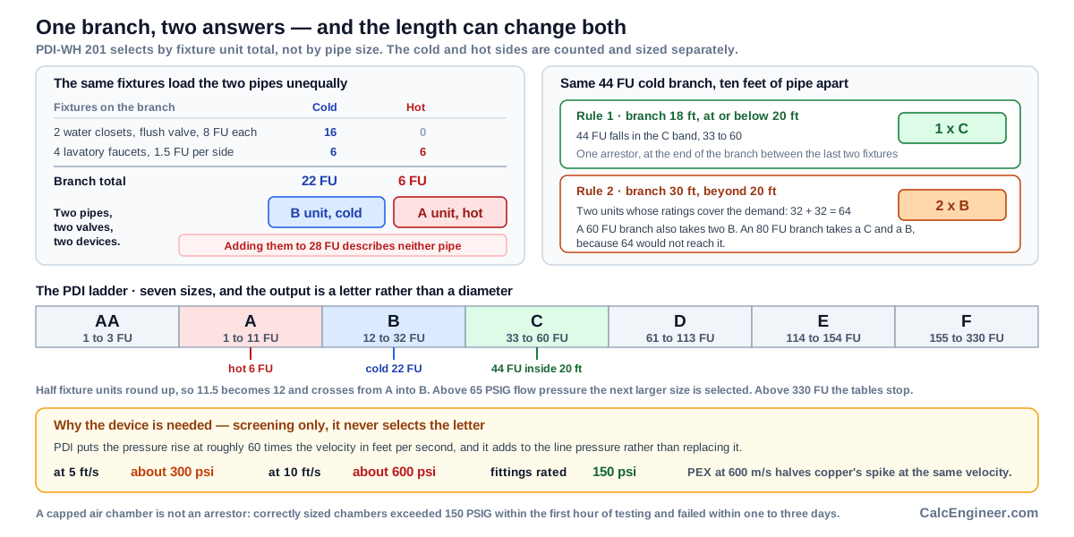
The ladder runs AA for 1 to 3 fixture units, A for 1 to 11, B for 12 to 32, C for 33 to 60, D for 61 to 113, E for 114 to 154, and F for 155 to 330. AA is the smallest unit and F the largest. Above 330 fixture units the standard stops and the arrangement becomes an engineered design.
Two details in the standard change answers and are easy to miss. Half fixture units round up, so a total of 11 and a half is treated as 12 and moves from A into B. And where the flow pressure in the branch exceeds 65 PSIG, the next larger size should be selected, so the same fixture unit total can produce a different letter on a high pressure system.
The letters are not pipe sizes and they do not correspond to connection diameters. A B unit on a three quarter inch branch and a B unit on a half inch branch are the same device class. What the letter describes is the capacity to absorb the shock produced by the fixtures on that branch, which is why the fixture unit total is the input.
The fixture unit values PDI uses come from its own table, which separates public and private fixtures and splits each fixture between cold and hot columns. A water closet on a flush valve counts 8 fixture units on the cold side in a public installation and nothing on the hot. A lavatory faucet counts one and a half on each side. Those splits are what make the two sides size separately.
Cold and Hot Arrestors Are Sized Separately
This is the difference between a correct specification and a plausible one, and it follows from how the fixture unit table is built.
PDI's table gives each fixture a total, a cold water figure and a hot water figure. A water closet on a flush valve is 8 fixture units, all of them cold. A lavatory faucet is 2 total, split one and a half cold and one and a half hot. A shower head on a mixing valve is 4 total in a public installation, split 2 cold and 3 hot, and the two do not add to the total because they do not occur together.
So the same group of fixtures produces two different totals. PDI's own example is a branch with two water closets at 8 fixture units each and four lavatories at one and a half each. The cold side carries 16 plus 6, which is 22, and selects a B unit. The hot side carries only the lavatories, which is 6, and selects an A unit. One branch, two devices, two different sizes.
The physical reason is straightforward. The cold and hot branches are separate pipes running to separate valves, and a shock wave in one has no path into the other. An arrestor on the cold side does nothing for a hot side surge.
Adding the totals together produces a number that describes neither pipe. In the example above, 22 plus 6 is 28, which selects a single B unit: too much device for the hot side and a device on the wrong pipe if it is fitted to the cold. This calculator returns one answer per active side, and where a side carries zero fixture units it reports that side as not present rather than selecting the smallest unit for it.
The 20 Foot Branch Rule
The fixture unit total picks the letter. The branch length decides how many arrestors the branch needs, and PDI states both cases as numbered rules.
Rule 1 covers multiple fixture branch lines that do not exceed 20 feet, measured from the start of the horizontal branch line to the last fixture supply on that branch. One arrestor serves the branch, and it is placed at the end of the branch line between the last two fixtures served.
Rule 2 covers branches that exceed 20 feet. Two arrestors are installed, and the standard gives the sizing rule plainly: the sum of the fixture unit ratings of the two units shall be equal to or greater than the demand of the branch.
That rule makes the long branch case computable, and it produces answers a single lookup would not. PDI's own examples show it. A cold branch of 48 fixture units up to 20 feet takes one C unit. A cold branch of 60 fixture units over 20 feet takes two B units, because two B ratings of 32 sum to 64, which covers 60. A cold branch of 44 fixture units over 20 feet also takes two B units. A cold branch of 80 fixture units takes one C and one B, because 60 plus 32 is 92 and two B units at 64 would not be enough.
Notice what happens to the 44 fixture unit branch. Inside 20 feet it takes a single C unit, since 44 falls in the 33 to 60 band. Beyond 20 feet it takes two B units instead. Same fixtures, same total, different answer, and the only thing that changed was the length of pipe they sit on.
There is a practical limit to how long a branch should be. PDI notes that where a very long branch is involved, the water supply is generally fed to a mid point on the branch rather than to one end, which changes the arrangement again.
Water Hammer Arrestor Placement
A correctly sized arrestor in the wrong position does not protect the branch, and the standard gives different locations for different situations.
On a multiple fixture branch the established location is at the end of the branch line, between the last two fixtures served. That position lets the device see the shock from any valve on the branch, since the wave travels back along the pipe toward the point of relief.
On a long run of piping to a remote item of equipment the rule reverses. The arrestor goes as close as possible to the point of quick closure. At that location it controls the developed energy and prevents the shock wave from surging through the piping system at all, rather than absorbing it after it has already travelled.
Those two rules put the device at opposite ends of the pipe, which is why the branch type is an input rather than an assumption. A washing machine solenoid at the end of a 90 foot run needs its arrestor beside the valve, not back at the fixture group.
Equipment runs are also sized differently. Where a fixture branch uses the fixture unit tables, a long run to equipment is selected from tables indexed by nominal pipe diameter and length of run, at a stated flow pressure. A 1 inch line of 92 feet at 55 PSIG and 8 feet per second takes an E unit. A 2 inch line of 98 feet at 60 PSIG and 10 feet per second takes two F units. Those are different tables and this calculator names which method applies rather than mixing them.
The point of relief matters for both cases. PDI defines it as a larger mass of water in the system to which the branch connects, meaning a main or riser at least two nominal pipe sizes larger than the branch, or a tank or water heater. The shock wave surges back and forth between the point of closure and the point of relief until the energy dissipates, which is what produces the noise and the vibration.
Water Hammer Arrestor vs Air Chamber
The traditional means of control was a capped piece of pipe, the same diameter as the line it serves, between 12 and 24 inches long, fitted vertically above the fixture. It works when it is installed and it does not keep working, and the standard documents exactly how fast it stops.
The mechanism is simple. Water absorbs the trapped air during the flow cycle, turbulence accelerates it, and as the chamber becomes waterlogged it loses its ability to absorb shock. PDI has a word for the condition: waterlogged, defined as an air chamber whose normal air content has been displaced by water.
The failure data is the part worth knowing. Air chambers correctly sized by the Dawson method were tested by the United States Testing Company at 60 PSIG flow pressure and 10 feet per second, at about 1,900 valve closures per day. Every size tested exceeded 150 PSIG within the first hour. Complete failure, evidenced by violent pounding and vibration in the piping, followed within one to three days.
A second belief the standard addresses is that the air can be replenished by closing the branch valve and opening the fixture trim. It cannot. The supply piping forms a trap, so there is no way to drain enough water to let air back in, and no practical rearrangement of the piping changes that.
An engineered arrestor uses the same principle and solves the problem by construction. The gas or air is permanently sealed in the unit behind a bellows, a piston or a bladder, so it cannot dissolve into the water. In the direct comparison PDI publishes, a calculated air chamber initially held the shock just under 150 PSIG, exceeded it within 250 cycles and passed 250 PSIG by around 4,400 cycles. A certified A unit held the shock well under 150 PSIG for 5,000 cycles at ambient temperature, then for another 5,000 cycles at 180 F.
The field consequence is that a house with hammer may already have something that looks like protection. From outside the wall a waterlogged air chamber and a working arrestor are indistinguishable, and hammer returning after a period of quiet is usually the clue.
Surge Pressure and Pipe Material
The pressure a closing valve creates is larger than the system it is closing on, and the standard is direct about the numbers.
The relation is Joukowsky's: the pressure rise equals the specific weight of the liquid multiplied by the velocity of the pressure wave multiplied by the change in flow velocity, divided by 144 times the acceleration due to gravity. PDI gives the wave velocity in water as 4,000 to 4,500 feet per second and then simplifies the whole thing to a rule of thumb: the pressure rise is approximately 60 times the velocity.
At the velocities engineers actually design to, that produces the figures the standard quotes. Between 5 and 10 feet per second the shock pressure runs 300 to 600 psi. Most valves and fittings in a plumbing distribution system are designed for a normal maximum rated pressure of 150 PSIG. So an ordinary branch at an ordinary velocity produces a spike two to four times the rating of what it is connected to, and the surge adds to the flow pressure rather than replacing it.
Material changes the wave speed and therefore the surge. Copper carries a wave speed near 1310 metres per second and steel near 1360, while PEX is closer to 600. At the same velocity a PEX branch produces roughly half the spike of a copper one. That is a real lever, and it is a design decision made long before anyone specifies an arrestor.
Velocity is the other lever and it is more direct, since the surge scales with it one for one. A branch designed at 5 feet per second rather than 8 has already cut the spike by nearly 40 percent.
Two things the standard adds that are easy to miss. The intensity depends particularly on the last 15 percent of valve closure, which is why solenoid and spring loaded valves are the classic cause. And noise is not the test: quick closure always creates some degree of shock, with or without audible sound, so a quiet system is not necessarily a protected one.
This calculation is screening. It explains why the device is needed and it does not select the unit letter, which comes from the fixture unit total.
ASSE 1010 Versus PDI-WH 201
Two standards apply to the same device and they do different jobs, which is worth knowing when a specification cites one and a submittal cites the other.
PDI-WH 201 is the sizing standard. It is what produces the unit letter from the fixture unit total, the count from the branch length, and the placement from the branch type. It also runs the certification programme: any manufacturer, member or not, may have units tested by a qualified independent laboratory, and only units certified as identical to the tested unit may carry the PDI certification mark.
The PDI certification test is specific. The unit is installed on a 50 foot test length of schedule 40 steel pipe at 60 PSIG flow pressure, and a quick closing surge valve terminating flow in no more than 25 milliseconds produces a total pressure of 400 PSIG for sizes A through F, or 250 PSIG for AA. The unit passes by completing 10,000 cycles, 5,000 at ambient temperature and 5,000 with water at a minimum of 180 F, without the reduced pressure exceeding 160 PSIG for any ten consecutive cycles.
ASSE 1010 is the performance and certification standard, with ANSI A112.26.1M as the parallel designation, and its current edition is 2021. It defines the device class and sets pressure, temperature and endurance requirements. Under it a device must be designed to withstand a maximum pressure of at least 150 psi and must operate at pressures from 0 to 60 psi. That operating range is a requirement on the device, proving it still functions at low line pressure, rather than a limit on where it may be installed.
The scope sentence in ASSE 1010 is the one that settles the air chamber question. The standard applies only to devices with a permanently sealed cushion of gas isolated from the waterway, designed to provide continuous protection, without maintenance, against detrimental surge pressures. The words without maintenance are the whole distinction, and the 2004 edition read water or gas where the current one reads gas.
Neither standard publishes a surge magnitude for a specific installation, which is why the figures in the screening block on this page are estimates from typical wave speeds rather than certified values.
What is a Water Hammer Arrestor
A water hammer arrestor is a device fitted to a water branch to absorb the pressure spike produced when a valve closes quickly. Inside it a sealed cushion of gas sits behind a bellows, a piston or a bladder, so the moving column of water has somewhere to go for the fraction of a second it takes to stop.
Water hammer itself is defined by the standard as the destructive forces, pounding noises and vibration that develop when a column of non compressible liquid flowing through a pipe is stopped abruptly, and it compares the forces generated at the point of stoppage to an explosion. The wave travels back through the piping until it reaches a point of relief, then surges back and forth between that point and the point of impact until the energy dissipates, which is what produces the noise and the vibration.
The damage list the standard gives is longer than most people expect: ruptured piping, leaking and weakened connections, pipe vibration and noise, damaged valves, check valves, water meters, pressure regulators and gauges, loosened hangers and supports, ruptured tanks and water heaters, and premature failure of other equipment.
Sizing is by fixture unit rather than by pipe diameter, which surprises people the first time. PDI chose the method deliberately, because it is quick, accurate and already familiar, and because most engineers size water distribution systems in fixture units anyway. The output is a letter from AA to F rather than a size in inches.
Key Facts
- PDI-WH 201, Water Hammer Arresters, is the sizing and certification standard, published by the Plumbing and Drainage Institute. PDI publishes it as a free download.
- The ladder has seven sizes: AA for 1 to 3 fixture units, A for 1 to 11, B for 12 to 32, C for 33 to 60, D for 61 to 113, E for 114 to 154, and F for 155 to 330.
- Sizing is by fixture unit total, not by pipe diameter. The output is a letter.
- Half fixture units round up. A total of 11 and a half is treated as 12.
- The cold and hot sides are sized separately from PDI's own fixture unit table, which splits each fixture between cold and hot columns. Two water closets and four lavatories give 22 fixture units cold, selecting a B unit, and 6 hot, selecting an A unit.
- Rule 1 covers multiple fixture branches up to 20 feet, which is 6.10 m, measured from the start of the horizontal branch to the last fixture supply. One arrestor serves the branch.
- Rule 2 covers branches over 20 feet. Two units are installed and the sum of their fixture unit ratings must be equal to or greater than the branch demand. A 60 fixture unit branch takes two B units, since 32 plus 32 covers it. An 80 fixture unit branch takes a C and a B, since 60 plus 32 is 92 and two B units would not reach it.
- The same 44 fixture unit branch takes one C unit inside 20 feet and two B units beyond it.
- Placement on a multiple fixture branch is at the end of the branch line, between the last two fixtures served. On a long run to equipment it is as close as possible to the point of quick closure, which is the opposite end of the pipe.
- Long runs to equipment are sized from tables indexed by nominal pipe diameter and run length, not from fixture units. A 1 inch line of 92 feet at 55 PSIG and 8 feet per second takes an E unit.
- PDI treats 55 PSIG as the ideal ceiling for flow pressure in a fixture branch and recommends a pressure reducing valve to hold it there. Where flow pressure exceeds 65 PSIG, the next larger size arrester should be selected.
- PDI gives the pressure rise as approximately 60 times the velocity in feet per second, and states that at the 5 to 10 feet per second engineers generally use, the shock pressure runs 300 to 600 psi.
- Most valves and fittings in a plumbing distribution system are designed for a normal maximum rated pressure of 150 PSIG.
- The pressure wave travels at 4,000 to 4,500 feet per second in water, and shock intensity depends particularly on the last 15 percent of the valve closure.
- Quick closure always creates some degree of shock, with or without audible noise, so the absence of noise does not mean water hammer is absent.
- The PDI certification test applies 400 PSIG total pressure for sizes A through F, and 250 PSIG for AA, on a 50 foot test pipe at 60 PSIG flow pressure with flow termination in no more than 25 milliseconds. A unit passes by completing 10,000 cycles, half of them at 180 F, without the reduced pressure exceeding 160 PSIG for any ten consecutive cycles.
- Correctly sized air chambers tested under those conditions exceeded 150 PSIG within the first hour and failed completely within one to three days at about 1,900 valve closures per day.
- Air chambers cannot be recharged by closing the branch valve and opening the fixture trim, because the supply piping forms a trap and no practical rearrangement lets air back in.
- ASSE 1010, current edition 2021, applies only to devices with a permanently sealed cushion of gas isolated from the waterway, designed to provide continuous protection without maintenance. Under it a device must withstand at least 150 psi and operate from 0 to 60 psi, which is a requirement on the device rather than a limit on where it is installed.
Applications
- An engineer specifying arrestors for a multi storey building sizes each branch from its fixture unit totals and gets a letter and a count for each side rather than one device per branch.
- A plumber roughing in a bathroom group works out whether the hot and cold branches need the same unit, and usually finds they do not.
- A contractor with a branch running the length of a long apartment checks whether the 20 foot rule applies and what pair of units covers the demand.
- A service technician called to a house that bangs every time the washing machine fills checks whether the existing protection is a certified arrestor or a capped air chamber that waterlogged years ago.
- A designer choosing between copper and PEX for a branch with quick closing valves sees that the material choice roughly halves the surge before any device is fitted.
- A designer on a high pressure system checks whether the flow pressure pushes the selection up a size, and whether a pressure reducing valve should be holding the branch at 55 PSIG instead.
- A plans reviewer checks that a submittal sized the arrestors from fixture units rather than from pipe size, and that the cold and hot sides were counted separately.
Example Calculations
Example 1. One branch, two answers
Given: PDI's own example. A branch serving two water closets on flush valves at 8 fixture units each, and four lavatory faucets at one and a half fixture units per side. Branch length inside 20 feet.
The cold side carries 16 from the water closets plus 6 from the lavatories, which is 22 fixture units, and 22 falls in the B band. The hot side carries only the lavatories, which is 6 fixture units, and 6 falls in the A band.
Result: a B unit on the cold branch and an A unit on the hot branch. Adding the two totals to 28 would have returned a single B unit, which is the right size for the wrong problem, because it protects one pipe and leaves the other unprotected. The two sides are different pipes running to different valves.
Example 2. The length changes the answer with nothing else changing
Given: a cold branch carrying 44 fixture units, first at 18 feet and then at 30 feet.
At 18 feet Rule 1 applies. Forty-four falls in the C band, so one C unit serves the branch, placed at the end between the last two fixtures.
At 30 feet Rule 2 applies. Two units are required and their combined fixture unit ratings must cover the demand. Two B units rate 32 each, and 32 plus 32 is 64, which covers 44.
Result: one C unit becomes two B units, and the only thing that changed was ten feet of pipe. PDI publishes this case directly, along with a 60 fixture unit branch that also takes two B units and an 80 fixture unit branch that takes one C and one B, because two B units at 64 would not reach 80.
Example 3. The band boundary
Given: a cold branch at exactly 32 fixture units, and a second at 33.
Thirty-two is the top of the B band and 33 is the bottom of the C band.
Result: one fixture unit apart and a different letter. This is worth attention because the standard also says half fixture units round up, so a calculated total of 32 and a half becomes 33 and crosses the boundary. A rounding decision made earlier in the calculation can change the device.
Example 4. Flow pressure moves the selection up a size
Given: a cold branch of 22 fixture units, first at 60 PSIG flow pressure and then at 70 PSIG.
At 60 PSIG the total selects a B unit from the table.
At 70 PSIG the flow pressure exceeds 65, so the next larger size is selected and the answer becomes a C unit.
Result: the same fixtures on the same branch take a different device because of the pressure behind them. PDI adds that a fixture branch should ideally never exceed 55 PSIG and that a pressure reducing valve should be installed to maintain proper pressure, so a branch sitting above 65 PSIG is worth looking at for a different reason as well.
Example 5. Equipment runs use a different method entirely
Given: a 1 inch line running 92 feet to a piece of equipment with a quick closing valve, at 55 PSIG flow pressure and 8 feet per second.
This is not a fixture branch, so the fixture unit tables do not apply. The selection comes from the equipment tables, indexed by nominal pipe diameter and length of run, and returns an E unit. Placement changes too: the arrestor goes as close as possible to the point of quick closure rather than at the end of a branch.
Result: an E unit next to the valve. For comparison, a 2 inch line of 98 feet at 60 PSIG and 10 feet per second takes two F units. Feeding a fixture unit total into the equipment method, or the reverse, produces a wrong answer in both directions.
Example 6. Why the device is needed
Given: a branch running at 5 feet per second, and the same branch at 10.
PDI's rule of thumb puts the pressure rise at roughly 60 times the velocity, so 5 feet per second produces about 300 psi and 10 feet per second about 600 psi. Both add to the flow pressure rather than replacing it.
Result: valves and fittings in a plumbing distribution system are generally designed for a normal maximum rated pressure of 150 PSIG. An ordinary branch at an ordinary design velocity therefore produces a spike between two and four times what the fittings are rated for, every time a quick closing valve shuts. And the standard notes that noise is not the indicator, since quick closure always creates shock whether or not anything is audible.
Example 7. What a capped air chamber actually does
Given: an air chamber correctly sized by the Dawson method, on a 50 foot line at 60 PSIG flow pressure and 10 feet per second, cycling at about 1,900 valve closures per day.
On installation it holds the shock to just under 150 PSIG, which is what it was designed to do.
Result: it exceeds 150 PSIG within the first hour and fails completely, with violent pounding and vibration in the piping, within one to three days depending on size. A certified PDI unit under the same conditions held the shock well under 150 PSIG for 5,000 cycles at ambient temperature and another 5,000 at 180 F. The chamber cannot be recharged in place either, because the supply piping forms a trap and no amount of draining lets air back in.
Standards & References
- Plumbing and Drainage Institute, PDI Standards page PDI publishes Standard WH201-2017, Water Hammer Arresters, as a free download. This is the sizing standard behind the unit ladder, the fixture unit method, Rules 1 and 2 for branch length, the pressure adjustment above 65 PSIG, the equipment run tables, the placement guidance and the certification programme.
- PDI-WH 201, revised 2010, full text as published in a manufacturer catalogue Useful for reading the sizing tables, the worked examples, the air chamber failure data and the certification procedure without a purchase. Note that this is the earlier revision and the current one is 2017.
- ASSE 1010-2021, Performance Requirements for Water Hammer Arresters The current edition of the performance and certification standard, with ANSI A112.26.1M as the parallel designation. It defines the device class and sets the pressure, temperature and endurance requirements a certified device is tested against.
- ANSI/ASSE 1010-2004, publicly available preview pages Carries the scope statement without purchase. Useful for reading how the standard defines the device class, and for seeing that the earlier edition read water or gas where the current one reads gas.
- Note on attribution PDI-WH 201 is the sizing standard and it produces the unit letter, the count and the placement. ASSE 1010 is the performance standard against which a certified device is tested. The air chamber failure figures on this page come from tests conducted for PDI by the United States Testing Company and are reported in the standard. The surge figures come from the standard's own rule of thumb and from typical wave speeds for each material, which vary with wall thickness and restraint, so treat them as screening rather than as certified values for a particular installation. Where a figure here comes from the 2010 revision, the 2017 revision should be checked before it is relied on for design.
Units
Pressure is entered and reported in pounds per square inch and kilopascals. Convert with 1 psi equal to 6.895 kPa. The 150 PSIG fitting rating is 1034 kPa, the 160 PSIG certification limit is 1103 kPa, the 400 PSIG test pressure is 2758 kPa, the 65 PSIG selection threshold is 448 kPa and the 55 PSIG ideal ceiling is 379 kPa.
Length is entered in feet or metres, with 1 foot equal to 0.3048 m, so the 20 foot branch rule is 6.10 m and the 50 foot certification test pipe is 15.24 m. Velocity converts the same way, so 5 feet per second is 1.52 m/s and 10 feet per second is 3.05 m/s.
Fixture units are dimensionless and identical in both systems, and so are the PDI unit letters. A B unit is a B unit whichever units the rest of the calculation is in, because the ladder is defined on fixture units rather than on any physical dimension.
Wave speed appears in both conventions. PDI quotes 4,000 to 4,500 feet per second for water, which is 1219 to 1372 m/s, and material figures are usually published in metres per second. Closure times are in milliseconds in both systems.
The internal unit selector governs the fields, labels, math, on-screen result and any exported result, and it takes priority over any site-wide unit switch. Switching converts the values you entered rather than reinterpreting them, so 20 feet becomes 6.10 m and returns to exactly 20 feet when switched back.
Limitations
- This calculator sizes arrestors for fixture branches from fixture unit totals. Long runs of piping to a remote item of equipment are sized from a different set of tables, indexed by nominal pipe diameter and run length at a stated flow pressure, and the calculator names which method applies rather than mixing them.
- Above 330 fixture units the PDI tables stop and the arrangement becomes an engineered design.
- Rule 2 requires two units whose combined fixture unit ratings cover the branch demand. Several pairs can satisfy that, and this calculator returns the pair with the least combined capacity that still covers the demand, drawn from sizes A through F. AA is a 1 to 3 fixture unit device tested at a lower total pressure than the rest of the ladder and PDI's Rule 2 examples never pair it, so it is left out of the pairing; including it would return an AA with a C for a 44 fixture unit branch, where the standard publishes two B units. On that basis the pairing reproduces every Rule 2 example in the standard. A different pair that also meets the stated rule is not wrong.
- Where the flow pressure exceeds 65 PSIG the one step size increase is applied to every unit selected on that side, including both members of a Rule 2 pair. PDI states the increase as a property of the selection rather than of the branch, and applying it to one unit of a pair and not the other would leave half the branch on the unadjusted table.
- The fixture unit values in PDI-WH 201 are its own and are not always the same as the water supply fixture units used to size pipe. A total taken from a pipe sizing calculation is a reasonable starting point and the result is marked preliminary.
- The surge calculation is screening. It shows why the device is needed and it does not select the unit letter, which comes from the fixture unit total under the sizing standard.
- Wave speeds are typical for each material rather than exact for a specific pipe, since they vary with wall thickness and restraint. PDI's own rule of thumb, a pressure rise of roughly 60 times the velocity, is a simplification of the same relation, and it is what this page uses where no material is stated.
- Placement distances quoted in manufacturer literature vary. The standard gives the location in words rather than in feet for fixture branches, so check the maximum distance for the listed arrestor being installed.
- Several figures on this page were read from the 2010 revision of PDI-WH 201, which is the revision available as full text. The current revision is 2017 and should be checked before any figure here is relied on for design.
- Pump trip, column separation, surge on municipal mains and the loading a surge places on pipe supports are different problems with different remedies and are not covered here.
Common Mistakes to Avoid
- Sizing the arrestor by pipe size. The PDI method is by fixture unit total and the output is a letter, not a diameter. Two branches with the same fixture unit total take the same unit whatever their connection size.
- Adding the cold and hot totals together. They are separate pipes feeding separate valves and they get separate devices. PDI's own example gives 22 fixture units cold and 6 hot on one branch, selecting a B and an A. Adding them to 28 describes neither pipe.
- Fitting one arrestor to a branch over 20 feet. Rule 2 requires two, with their combined ratings covering the demand. One device on a 30 foot branch leaves it under protected even when the letter is right.
- Assuming the letter stays the same when the branch gets longer. A 44 fixture unit branch takes one C unit inside 20 feet and two B units beyond it. Same fixtures, different answer.
- Ignoring the flow pressure. Above 65 PSIG the next larger size should be selected, so the same fixture unit total produces a different letter on a high pressure system. PDI also treats 55 PSIG as the ideal ceiling for a fixture branch.
- Rounding a half fixture unit down. The standard says round up: 11 and a half becomes 12, which moves the selection from A into B.
- Using the fixture branch method for a run to equipment. Equipment runs are selected from pipe diameter and run length, and the arrestor goes beside the valve rather than at the end of a branch. The two methods are not interchangeable in either direction.
- Putting the arrestor at the wrong end. On a multiple fixture branch it belongs at the end, between the last two fixtures. On a run to a single piece of equipment it belongs next to the valve that slams. Those are opposite ends of the same pipe.
- Trusting a capped air chamber. Correctly sized chambers exceeded 150 PSIG within the first hour of testing and failed within days. From outside the wall a waterlogged chamber and a working arrestor are indistinguishable.
- Believing an air chamber can be recharged by draining the branch. It cannot. The supply piping forms a trap and there is no practical way to let air back in.
- Treating silence as protection. The standard is explicit that quick closure always creates some degree of shock with or without audible sound, so the absence of noise does not mean the branch is free of transients.
- Reading the surge figure as the sizing basis. The surge shows why the device is needed. The fixture unit total selects it.
Frequently Asked Questions
How do I size a water hammer arrestor?
What are PDI units AA to F?
Do I need separate arrestors for hot and cold?
What is the 20 foot rule for water hammer arrestors?
Can one arrestor protect a whole branch?
Where should a water hammer arrestor be installed?
Is an air chamber the same as a water hammer arrestor?
Can I recharge an air chamber by draining the pipes?
How much pressure does water hammer actually create?
Does the pipe material change the size of the surge?
Does high water pressure change the arrestor size?
Can I use water supply fixture units from a pipe sizing calculation?
My pipes are quiet, so I do not have water hammer. Is that right?
Frequently Used Together
Engineers often use these calculators in combination for complete project workflows:
Related Calculators
Explore similar calculators that might be useful for your project:
Plumbing Quick Reference — Keep It On Your Phone On Site
A 10-page field reference for catching pressure, velocity, slope, and pump-sizing mistakes before you order pipe, close a wall, or add a booster.
- Velocity limits, fixture pressure minimums, drain slope, and the 80 psi ceiling in one table
- Worked examples that show why a single pressure number gives four different answers
- Keep it on your phone, or print the two field-check pages
Free PDF. Calculators stay free. Unsubscribe anytime.
Calculate
This selector governs every field, label, result and export on this page, and it takes priority over the site header switch. Switching converts the values you entered rather than reinterpreting them, so 20 ft becomes 6.1 m and returns to exactly 20 ft when you switch back. Fixture units and PDI unit letters are dimensionless and identical in both systems.
Branch Load
The fixture units the cold branch carries, from the cold water column of the fixture unit table. Enter zero if the branch has no cold side; a blank field means the figure was not entered and is a different answer. Half fixture units round up under the standard, and the calculator does that for you and says so.
Entered separately, and never added to the cold total. A water closet on a flush valve counts on the cold side and nothing on the hot, so the two totals are usually different and the two sides usually take different devices. Enter zero where the branch has no hot side.
PDI-WH 201 carries its own fixture unit table, which separates public and private fixtures and splits each between cold and hot columns. Those values are not always the same as the water supply fixture units used to size pipe, so a total from a pipe sizing calculation is a reasonable starting point and the selection is marked preliminary.
Branch Geometry
Measured from the start of the horizontal branch line to the last fixture supply on that branch. This is what decides how many arrestors the branch needs: up to 20 feet, which is 6.10 m, one serves it, and beyond that PDI requires two whose combined ratings cover the demand.
Placement depends on this, and so does the method. A multiple fixture branch is sized from fixture units and the device goes at the end of the branch. A long run to a single item of equipment is sized from pipe diameter and run length instead, and the device goes beside the valve, which is the opposite end of the pipe.
Flow Pressure (optional)
Where the flow pressure exceeds 65 PSIG, which is 448 kPa, PDI selects the next larger size arrester, so the same fixture unit total can produce a different letter. The standard also treats 55 PSIG as the ideal ceiling for a branch line serving fixtures. Leaving this blank returns the selection without the adjustment.
Surge Screening (all optional)
The material sets the speed of the pressure wave and therefore the size of the surge. PEX produces roughly half the spike of copper at the same velocity. These are typical figures for the material rather than exact for a specific pipe, since wave speed also depends on wall thickness and restraint. With no material stated the calculator uses PDI's own rule of thumb instead.
The velocity in the branch before the valve closes. The surge scales with it one for one, which makes it the most direct lever anyone has on the size of the spike. PDI states that at the 5 to 10 feet per second engineers generally design to, the shock pressure runs 300 to 600 psi.
The pressure the line already holds. The surge adds to it rather than replacing it, so without this figure the peak at the fixture cannot be reported and no comparison against a fixture rating is made. Reporting the surge on its own understates what the connection actually sees.
The rated pressure of the valve, connector or appliance on the end of the branch. Left blank, the calculator uses 150 psi, which is the normal maximum rated pressure most valves and fittings in a plumbing distribution system are designed for, and it names the default in the result. The figure varies by product, so enter the real one where you have it.
How long the valve takes to shut. A solenoid valve on a dishwasher or washing machine closes in about 10 milliseconds, which is why those appliances are the classic cause of hammer. Compared against the critical closure time to show whether the full surge develops.
From the point of valve closure to the point of relief, which PDI defines as a main or riser at least two nominal pipe sizes larger than the branch, or a tank or water heater. With the pipe material it gives the critical closure time, twice this length divided by the wave speed.