Tank Drain Time Calculator — Gravity & Orifice
On this page
Calculate
Vertical cylinder, rectangular, and custom-constant shapes use the exact falling-head formula. Horizontal cylinder and conical frustum use numerical integration (plan area varies with level).
Inside diameter of the vertical cylindrical tank.
Height of the orifice centerline above the inside bottom of the tank. Enter 0 for a bottom outlet (centerline at the bottom). For a low-side outlet, enter the height of its center above the tank floor.
Initial liquid head: the height of the liquid surface above the orifice centerline at the start of draining. If the outlet is at the tank bottom (elevation = 0), this equals the initial liquid depth.
Drain to the orifice centerline (no head remaining, flow stops) or to a specified final head above the orifice (e.g. to keep a pump suction submerged).
Inside diameter of the orifice or outlet opening. US: inches (converted to feet internally before computing area). Metric: millimetres.
The entrance type sets the discharge coefficient Cd. A reentrant (Borda) mouthpiece runs about 0.50, lower than a sharp-edged hole, not higher. A long pipe, hose, or valve adds friction the orifice model does not include; use a pipe-flow method for those.
Length of the outlet stub or pipe. Used with the outlet diameter to compute L/D. If L/D exceeds about 10, a pipe-flow advisory is triggered (the orifice estimate becomes optimistic).
A sealed tank forms a partial vacuum as liquid leaves, slowing the drain. If the tank is not vented or you are unsure, a venting advisory is shown and the ideal drain time is a lower bound.
Optional target time in seconds. If entered, the result includes a WITHIN TARGET / OVER TARGET verdict comparing the computed drain time to this target.
Standard acceleration due to gravity. Default: 9.81 m/s² (metric) or 32.2 ft/s² (US). Change only for non-standard installations (e.g. high altitude or pressurized vessels; note the model does not otherwise account for overpressure).
Overview
How long a tank takes to empty through a bottom or low-side opening is a falling-head problem, not a constant-flow one. As the liquid level drops, the pressure driving the flow drops with it, so the tank empties quickly at first and slowly near the end. This calculator uses Torricelli's law with the falling-head integration to find the drain time, the initial and average flow, and a level-versus-time table that shows the slow tail.
Three things set the answer: the tank's plan area, the outlet area, and the discharge coefficient. A wider tank holds more liquid per unit of height and takes longer; a bigger outlet drains faster; and the discharge coefficient captures how cleanly the flow leaves the opening. The coefficient is the biggest source of uncertainty, so it is worth matching to the outlet type.
This is a free-discharge orifice model. It assumes the liquid leaves through an opening under gravity, into open air, from a vented tank. If the outlet is really a long pipe or hose, has a valve, or the tank is sealed, the actual drain time will be longer than this ideal estimate, and the tool flags those cases.
What to Look at First
Drain Time. The primary output: how long the tank takes to drain from the initial head to the final level. This is the number to compare against a process or emergency drain requirement.
Level-vs-Time Table. Shows the elapsed time at 100%, 75%, 50%, 25%, 10%, and final head. The slow tail (the last 10–20% of head) often takes as long as the first 80% combined. Size drain systems for the tail, not the start.
Advisories. If a Pipe-Flow, Venting, or Small-Orifice advisory is active, the ideal time shown is a lower bound; the actual drain time will be longer. Check those flags before using the result in a design.
How to Use This Calculator
Choose the unit system: US (feet, inches, gallons, gpm) or Metric (metres, mm, litres, L/s).
Pick the tank shape: vertical cylinder, rectangular, horizontal cylinder, conical frustum, or a custom constant area.
Enter the tank dimensions for the selected shape.
Enter the outlet centerline elevation above the tank bottom, and the initial liquid head (surface to orifice centerline).
Choose whether to drain to the orifice centerline (Hf = 0) or to a specified final level.
Enter the outlet diameter and select the outlet type, which sets the discharge coefficient Cd. Or enter Cd directly.
Optionally enter the outlet length (for the pipe-flow L/D check), whether the tank is vented, and a target time.
Click Calculate to see the drain time, flow rates, volume drained, the level-versus-time table, and any advisories.
Head is always measured from the liquid surface to the orifice centerline, not to the tank bottom. Draining to zero head means the surface reaches the orifice, not that the tank is physically empty; a low-side outlet leaves a heel below it.
Inputs & Outputs
Inputs
Units & Tank Shape
Tank Dimensions
Head & Drain Target
Outlet & Discharge Coefficient
Tank Condition & Target
Advanced
Outputs
Primary Results
Volume & Level
Basis & Advisories
Target Check (optional)
Level-vs-Time Table
Formula
Tank Drain Time Formulas
Orifice flow (Torricelli's law)
ideal_velocity = sqrt(2 g h)          ideal jet velocity at head h
Q(h) = Cd x Ao x sqrt(2 g h)          flow (Cd is on the flow, not the jet speed)
Ao = pi x d_out^2 / 4                 orifice area
Head and liquid level
h = liquid surface above orifice centerline
liquid_level = outlet_elevation + h
Hf = 0 means surface reaches orifice (tank is NOT physically empty if outlet is above the bottom)
Constant plan area: exact formula (vertical cylinder, rectangular, custom)
t = 2 x At x (sqrt(Hi) - sqrt(Hf)) / (Cd x Ao x sqrt(2 g))

Drain to centerline (Hf = 0):
  t = 2 x At x sqrt(Hi) / (Cd x Ao x sqrt(2 g))

At: pi x D^2 / 4  (vertical cylinder)
    L x W         (rectangular)
    entered value  (custom constant)
Varying plan area: numerical (horizontal cylinder, conical frustum)
t = integral from Hf to Hi of A(outlet_elev + h) / (Cd x Ao x sqrt(2 g h)) dh

Horizontal cylinder at level z:
  chord_width = 2 x sqrt(max(0, 2 r z - z^2))
  A_surface   = L x chord_width

Conical frustum at level z (vertical axis):
  r(z) = r_bottom + (r_top - r_bottom) x z / H_cone
  A_surface = pi x r(z)^2
Flow rates
Q_init  = Cd x Ao x sqrt(2 g Hi)
Q_final = Cd x Ao x sqrt(2 g Hf)    (0 if Hf = 0)
Q_avg   = V_drained / t              (always lower than Q_init)
Conversions
g = 9.81 m/s² = 32.2 ft/s²
sqrt(2g) = 4.429 (SI) / 8.02 (US)
1 gal = 3.785 L
1 ft = 0.3048 m
1 gpm = 0.0631 L/s
US outlet in inches: Ao(ft²) = pi x (d_in / 12)^2 / 4
| Symbol | Meaning |
|---|---|
| h | Head: liquid surface above orifice centerline |
| Hi, Hf | Initial and final heads |
| At | Tank plan area (constant for vert/rect/custom) |
| Ao | Orifice area |
| Cd | Discharge coefficient (on flow, not jet speed) |
| g | Gravitational acceleration |
| Q_avg | Average flow = volume drained / time |
| outlet_elevation | Orifice centerline height above tank bottom |
Decision Model
The calculator returns the drain time for any valid input combination. The basis badge tells you which formula was used: COMPUTED means the exact closed-form equation; NUMERICAL means the plan area changes with height and numerical integration was used instead.
Advisories are independent of the basis badge. A PIPE-FLOW-ADVISORY fires when the outlet is long enough (L/D > 10), or when the outlet type is a long pipe, hose, or valve; the orifice formula does not include pipe friction, so the ideal time is a lower bound. A VENTING-ADVISORY fires when the tank is closed or the vent status is unknown; a vacuum forming above the liquid slows the actual drain. A VERY-SMALL-ORIFICE-ADVISORY fires for outlets under about 5 mm, where surface tension, debris, and viscosity can dominate.
The target verdict, if a target time is entered, has four bands. Ratios below 1.00 are WITHIN TARGET; above 1.25 are OVER TARGET. When an advisory is active and the ratio is ≤ 1.00, the verdict is softened to an advisory note because the actual time may push it past the target.
Why Tank Draining is a Falling-Head Problem
The core insight of this calculation is that the flow rate is not constant. At the start, when the liquid surface is high, the head is large and the flow is fast. As the level falls, the head falls with it, and so does the flow. The decrease follows a square root relationship: halving the head reduces the flow by a factor of the square root of two, not by half. This is why the tank empties quickly through the first 50% of head but lingers on the last 10%.
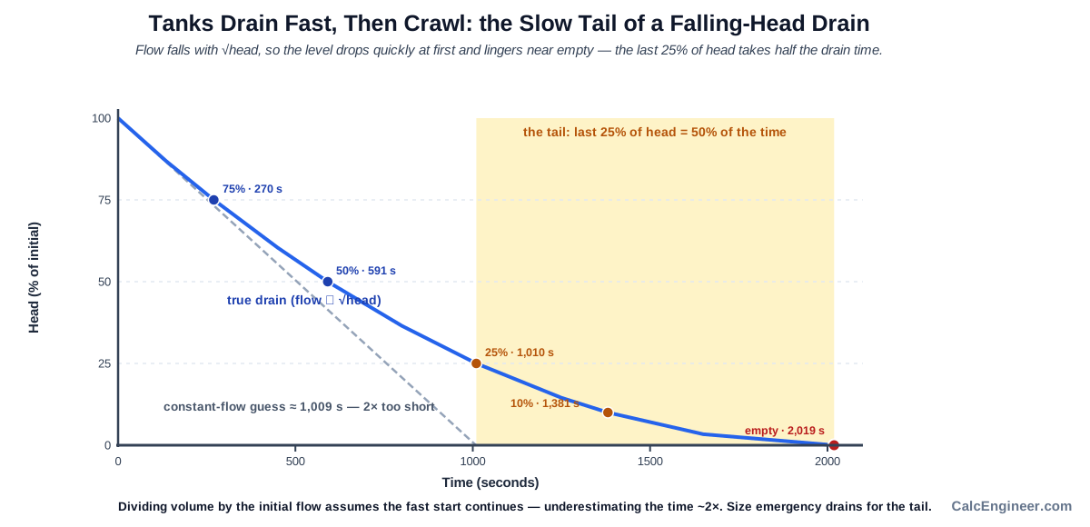
The consequence is that dividing the tank volume by the initial (or average) flow to estimate the drain time gives a result that is systematically too short. The correct method integrates the falling-head relationship over the full drain, which is what this calculator does. For constant-area tanks the integration has a closed form; for tanks where the plan area changes with height, it is done numerically.
What is Tank Drain Time
Tank drain time is the time it takes for a tank to empty through a gravity orifice from an initial liquid level to a final level. Because the flow driving force (the head) decreases as the tank drains, the process is not uniform: the first half of the drain is fast and the second half is slow. The falling-head calculation accounts for this non-linearity and returns the correct total time, along with a table showing how the level changes over time.
The key parameters are the tank's plan area (which sets how much liquid each unit of head drop represents), the outlet area (which sets how fast that liquid can leave), and the discharge coefficient (which accounts for the energy loss at the outlet entrance). The discharge coefficient is the biggest single lever on the result: a well-rounded entrance drains substantially faster than a sharp-edged hole of the same diameter, and a reentrant pipe stub drains slower than both.
Orifice Drain vs Pipe Drain
The model here is for a free-discharge orifice: liquid leaves through a short opening into open air. That is not the same as draining through a pipe, hose, or valve. A drain pipe adds friction losses that the orifice equation does not include, so the orifice estimate is optimistic (too fast) for any piped drain.
The practical boundary is the length-to-diameter ratio of the outlet. Below about 10 diameters, the orifice model is a reasonable approximation. Above that, pipe friction dominates and the orifice result becomes increasingly optimistic. The calculator checks L/D when the outlet length is entered and flags a pipe-flow advisory when the ratio exceeds 10.
Heel Volume and Low-Side Outlets
Draining to zero head means the liquid surface has reached the orifice centerline, not that the tank is physically empty. If the outlet is above the tank bottom, the liquid below it stays behind. This residual volume is the heel.
For a low-side outlet, the heel volume is the liquid between the tank floor and the orifice centerline. For a partial drain (Hf > 0), the heel includes all liquid below the final level. The calculator reports both the volume drained and the remaining heel, so the drain plan can account for the liquid that will not move by gravity through that outlet.
Key Facts
- Tank draining is a falling-head problem: flow decreases with the square root of the head, so the tank empties fast at first and slowly near the end.
- The drain time formula for a constant-area tank is t = 2·At·(√Hi − √Hf) / (Cd·Ao·√(2g)).
- The discharge coefficient Cd applies to the flow, not to a physical jet speed; it is the biggest source of uncertainty.
- A sharp-edged orifice runs about 0.61; a rounded or bellmouth entrance higher (0.75–0.98); a reentrant (Borda) entrance lower, around 0.50.
- Head is measured to the orifice centerline; draining to zero head means the surface reaches the orifice, not that the tank is physically empty.
- Horizontal cylinders and conical frustums use numerical integration because the plan area changes with the liquid height.
- A level-versus-time curve is more useful than a single average flow, because the drain rate changes throughout the cycle.
- This is a free-discharge orifice estimate; a long pipe, valve, submerged outlet, or unvented tank makes the real drain time longer.
Applications
- Estimating tank turnaround time for a process or storage tank drain.
- Checking an emergency drain or containment bund draindown against a required time.
- Comparing outlet diameter or entrance-type options to hit a required drain time.
- Planning a partial draindown to a heel level before maintenance.
- Estimating the heel volume left below a low-side outlet.
- Comparing a sharp-edged and a rounded outlet for drain performance.
- Verifying that a vented tank drains within the available window.
Example Calculation
Example 1: Vertical Cylinder, Partial Drain
Given: a vertical tank 2.0 m in diameter, a 50 mm sharp-edged bottom orifice (Cd = 0.62), draining from a 3.0 m head down to a 0.20 m head.
At = pi × 2.0² / 4 = 3.1416 m² Ao = pi × 0.050² / 4 = 0.0019635 m² t = 2 × 3.1416 × (sqrt(3.0) - sqrt(0.20)) / (0.62 × 0.0019635 × sqrt(2 × 9.81)) = 6.2832 × (1.7321 - 0.4472) / (0.62 × 0.0019635 × 4.429) = 6.2832 × 1.2849 / 0.005391 = 1497 s
Result: about 1497 seconds, or roughly 24 min 57 s, to drain from 3.0 m to 0.20 m.
Example 2: Full Drain Takes Longer Than Partial
Same tank, comparing partial drain (Hf = 0.20 m) with full drain to the centerline (Hf = 0).
Partial (Hf = 0.20 m): t = 1497 s (from Example 1) Full (Hf = 0): t = 2 × 3.1416 × sqrt(3.0) / (0.62 × 0.0019635 × 4.429) = 6.2832 × 1.7321 / 0.005391 = 2019 s
Result: draining the last 0.20 m adds about 522 seconds. The full drain (about 2019 s, 33 min 39 s) takes noticeably longer than the partial drain (1497 s), because the head is nearly gone near the end.
Example 3: Initial and Final Flow
Same tank at 3.0 m (start) and 0.20 m (end):
Q_init = 0.62 × 0.0019635 × sqrt(2 × 9.81 × 3.0) = 0.00934 m³/s ≈ 9.3 L/s Q_final = 0.62 × 0.0019635 × sqrt(2 × 9.81 × 0.20) = 0.00241 m³/s ≈ 2.4 L/s
Result: the flow starts at about 9.3 L/s and falls to about 2.4 L/s by the 0.20 m level. The average flow over the drain is lower than the initial, which is why the tail takes so long.
Example 4: The Coefficient Changes the Time
Same tank and outlet, comparing sharp-edged (Cd = 0.62) vs rounded (Cd = 0.80):
Time is inversely proportional to Cd. t(0.62) / t(0.80) = 0.80 / 0.62 = 1.29
Result: the sharp-edged outlet drains about 29% slower than the rounded one, for the same tank and opening. This is why matching Cd to the entrance type matters.
Example 5: US Units, Outlet in Inches
Given: a 2-inch outlet in a US-units tank.
d_out = 2 in → 2 / 12 = 0.1667 ft Ao = pi × 0.1667² / 4 = 0.02182 ft²
Result: the outlet diameter must be converted from inches to feet before computing the area. Using inches directly would give an area 144 times too large.
Example 6: Long Outlet Triggers Pipe-Flow Advisory
Given: a 50 mm outlet that is actually a 1 m long pipe stub.
L / D = 1000 mm / 50 mm = 20 20 > 10 → PIPE-FLOW-ADVISORY
Result: the outlet is 20 diameters long, past the roughly 10-diameter limit for the orifice model. The calculator shows the ideal orifice time as a baseline but flags the advisory. The actual drain time will be longer because of pipe friction.
Standards & References
- Crane Technical Paper No. 410 (TP-410): Flow of Fluids Through Valves, Fittings, and Pipe. Standard reference for orifice discharge coefficients and pipe flow.
- Brater and King, Handbook of Hydraulics: Classic reference for discharge through orifices under falling head. Basis for the analytical formula used here.
- Torricelli's law of efflux: discharge-coefficient values for sharp-edged, rounded/bellmouth, and reentrant entrances come from standard orifice-coefficient tables in the references above. Verify critical or non-water cases with a full hydraulic analysis.
Units
| Quantity | US (Imperial) | Metric | Note |
|---|---|---|---|
| Head / Dimensions | feet (ft) | metres (m) | 1 ft = 0.3048 m |
| Outlet diameter | inches (in) | millimetres (mm) | Converted to ft internally: Ao = π × (d/12)² / 4 |
| Area | ft² | m² | n/a |
| Volume | US gallons (gal) | litres (L) | 1 gal = 3.785 L |
| Flow rate | gpm | L/s | 1 gpm = 0.0631 L/s |
| Gravity | 32.2 ft/s² | 9.81 m/s² | √(2g) = 8.02 (US) or 4.429 (Metric) |
| Time | seconds | seconds | Shown as minutes or hours where the value warrants it |
Limitations
- This is a free-discharge orifice model using Torricelli's law with falling head. It does not model drain-pipe friction, a valve, a long outlet pipe (over about 10 diameters), or minor losses; use a pipe-flow method for those, and this ideal time will be optimistic.
- It assumes a vented tank at atmospheric pressure. A closed tank without a vent drains more slowly as a vacuum forms.
- It assumes clean, water-like fluid unless the discharge coefficient is adjusted. Viscous, non-Newtonian, or particle-laden fluids differ.
- It does not model vortex formation, air entrainment, surface tension at very small outlets, or a submerged or back-pressured outlet discharging into liquid.
- Hf = 0 means the level reaches the orifice centerline, not that the tank is physically empty. A low-side outlet leaves a heel below it.
- For horizontal cylinders and conical frustums the result is a numerical estimate (2000-step trapezoidal integration).
- It does not size the outlet, the pipe, or the containment. It is a planning estimate; verify critical, pressurized, viscous, or non-water cases with a full hydraulic analysis or a test, and against Crane TP-410 or Brater and King.
Common Mistakes to Avoid
- Assuming the tank drains at a constant rate. The flow falls with the square root of the head, so the tank slows down near the end.
- Dividing the tank volume by a constant or initial flow. The correct average flow comes from the falling-head integration; this shortcut gives too short a time.
- Ignoring the discharge coefficient, or using one value for every outlet. Cd runs about 0.61 for sharp-edged, higher for rounded, and lower for reentrant (Borda).
- Treating a long pipe or hose as an orifice. A pipe adds friction; use a pipe-flow method when the outlet length-to-diameter ratio exceeds about 10.
- Measuring head from the tank bottom instead of the orifice centerline. Head is the surface height above the orifice centerline.
- Assuming zero head means the tank is empty. It means the surface reached the orifice; a low-side outlet leaves a heel below it.
- Forgetting to convert an outlet diameter in inches to feet before computing the area in US units.
- Trusting an ideal time for a sealed tank. Without a vent, a vacuum forms above the liquid and slows the drain.
Frequently Asked Questions
How do you calculate tank drain time?
Is tank drain time linear?
Why does the tank drain slower as it empties?
What is the discharge coefficient and what value should I use?
What does draining to zero head mean?
Can I use this calculator for a drain pipe?
Does the calculator work for horizontal cylinders and cones?
Why is my sealed tank draining slower than the calculator says?
Frequently Used Together
Engineers often use these calculators in combination for complete project workflows:
Related Calculators
Explore similar calculators that might be useful for your project:
Plumbing Quick Reference — Keep It On Your Phone On Site
A 10-page field reference for catching pressure, velocity, slope, and pump-sizing mistakes before you order pipe, close a wall, or add a booster.
- Velocity limits, fixture pressure minimums, drain slope, and the 80 psi ceiling in one table
- Worked examples that show why a single pressure number gives four different answers
- Keep it on your phone, or print the two field-check pages
Free PDF. Calculators stay free. Unsubscribe anytime.
Calculate
Vertical cylinder, rectangular, and custom-constant shapes use the exact falling-head formula. Horizontal cylinder and conical frustum use numerical integration (plan area varies with level).
Inside diameter of the vertical cylindrical tank.
Height of the orifice centerline above the inside bottom of the tank. Enter 0 for a bottom outlet (centerline at the bottom). For a low-side outlet, enter the height of its center above the tank floor.
Initial liquid head: the height of the liquid surface above the orifice centerline at the start of draining. If the outlet is at the tank bottom (elevation = 0), this equals the initial liquid depth.
Drain to the orifice centerline (no head remaining, flow stops) or to a specified final head above the orifice (e.g. to keep a pump suction submerged).
Inside diameter of the orifice or outlet opening. US: inches (converted to feet internally before computing area). Metric: millimetres.
The entrance type sets the discharge coefficient Cd. A reentrant (Borda) mouthpiece runs about 0.50, lower than a sharp-edged hole, not higher. A long pipe, hose, or valve adds friction the orifice model does not include; use a pipe-flow method for those.
Length of the outlet stub or pipe. Used with the outlet diameter to compute L/D. If L/D exceeds about 10, a pipe-flow advisory is triggered (the orifice estimate becomes optimistic).
A sealed tank forms a partial vacuum as liquid leaves, slowing the drain. If the tank is not vented or you are unsure, a venting advisory is shown and the ideal drain time is a lower bound.
Optional target time in seconds. If entered, the result includes a WITHIN TARGET / OVER TARGET verdict comparing the computed drain time to this target.
Standard acceleration due to gravity. Default: 9.81 m/s² (metric) or 32.2 ft/s² (US). Change only for non-standard installations (e.g. high altitude or pressurized vessels; note the model does not otherwise account for overpressure).