Two Requirements on One Airflow
A spray booth answers to two separate requirements that arrive from unrelated directions, and the airflow installed has to satisfy both. That makes the first question of the design not how large either one is, but which of them is larger for the process at hand.
The first requirement is a dilution problem. Solvent evaporating from atomised paint produces vapour, and that vapour has to be held below a stated fraction of the concentration at which it would ignite. The airflow needed follows from how fast paint is sprayed and how much solvent it contains. Nothing about the size of the booth enters it. A small booth running an automatic line and a large booth running the same line carry the same vapour load.
The second requirement is a capture problem. Air has to move across the working section fast enough to carry overspray away from the operator and towards the filters rather than letting it drift into the shop. That airflow follows from the area of the working section and the velocity held across it. Nothing about what is being sprayed enters it. A booth spraying water-based primer and the same booth spraying a high-solvent topcoat need the same velocity.
The two previous articles in this group dealt with capture at or near a source, where distance and connection governed. Vehicle exhaust extraction takes the contaminant through a seal at the tailpipe. A welding hood collects across a gap, and the gap enters the requirement squared. A booth encloses the source completely, so distance disappears as a variable. What replaces it is a question with no general answer: which of two independent requirements is larger depends on the process and the booth together, and both have to be worked out before either can be relied on.
The calculator multiplies the booth opening area by a face velocity and by a booth type factor. It computes the second requirement and states plainly that it does not address the first. This article works out what the first one looks like, how sensitive the comparison between them is to the assumptions behind it, why the reference section the model uses does not suit every configuration, and what the resulting airflow costs once it has to be replaced as heated makeup air.
Calculator Inputs: An Opening, a Velocity, and a Factor
Three numeric fields, a selector and a unit toggle. The selector carries an assumption that the rest of this article works through.
Unit System. Imperial (ft, fpm, CFM) or Metric (m, m/s, m³/h). The category thresholds convert exactly, so a result keeps its band when the toggle moves.
Booth Opening Width and Booth Opening Height [ft or m]. The dimensions of the booth opening. A booth built for a passenger car typically has an opening 3.5 to 4.5 m (11 to 15 ft) wide and 2.5 to 3.0 m (8 to 10 ft) high. Their product is the reference area every result on the page is built on.
Target Face Velocity [fpm or m/s]. The air velocity in the plane of the opening. Required values differ by type of operation and by booth construction, and they are set by the applicable documents and by the booth manufacturer's data rather than by a figure that carries across installations.
Booth Type. Four configurations, each carrying a multiplier: Open Face 1.00, Crossdraft 1.00, Downdraft 1.15, Side Draft 1.10.
The outputs are the opening area, the required ventilation rate and a demand category.
Imperial: Q [CFM]  = W_ft × H_ft × V_fpm × F
Metric:   Q [m³/h] = W_m × H_m × V_m/s × 3600 × F

W   booth opening width          ft or m
      11 to 15 ft (3.5 to 4.5 m) for a passenger car booth
H   booth opening height         ft or m
      8 to 10 ft (2.5 to 3.0 m) for the same
V   face velocity in the plane of the opening
                                 fpm or m/s
      set by the applicable document and the booth design
F   booth type factor            dimensionless
      1.00, 1.00, 1.15 or 1.10 as listed above
The 3600 converts a flow per second into a flow per hour and belongs only to the metric form. In imperial, square feet multiplied by feet per minute is already cubic feet per minute.
On the multipliers:
The values 1.15 and 1.10 are screening allowances internal to this
calculator. They do not come from any code or standard, and they are
not precise engineering coefficients, which the page states directly.
Open Face and Crossdraft carry the same multiplier, so choosing
between those two does not change the result.
The result categories:
LOW        below 5,000 CFM (8,495 m³/h)
NORMAL     5,000 to 14,999 CFM (8,495 to 25,484 m³/h)
HIGH       15,000 to 29,999 CFM (25,485 to 50,969 m³/h)
VERY HIGH  30,000 CFM (50,970 m³/h) and above

The thresholds convert exactly: 5,000 × 1.699 = 8,495,
15,000 × 1.699 = 25,485 and 30,000 × 1.699 = 50,970, so a result does
not change band with the unit toggle. The bands are indicative sizing
ranges rather than limits set by any regulatory requirement.
What is absent from the fields:
The spray rate and the solvent content of the coating, which set the
second requirement on the airflow.
The depth of the booth, which for several configurations takes part
in defining the working section.
The outdoor design temperature, which sets the heating load of the
makeup air unit.
The Vapour Dilution Requirement and What Sets It
The requirement the calculator does not address is a dilution balance, and its size follows from the spray rate and the solvent content of the coating rather than from anything about the booth.
Solvent evaporates from the atomised paint and forms vapour. The requirement is that the vapour concentration stays below a stated fraction of the lower explosive limit. The applicable document sets that fraction, and for spray finishing operations it is commonly a quarter of the limit. Which document applies, and what fraction it states, differs between jurisdictions.
The chain that gives the airflow:
V_solvent = V_paint × f_solvent            [L/min]
m_solvent = V_solvent × ρ_solvent          [kg/min]
n         = m_solvent / M                  [mol/min]
V_vapour  = n × 24.055                     [L/min at 20 °C]
Q         = V_vapour / (LEL × fraction)    [volume/min]

V_paint     spray rate at the gun          L/min
              0.2 to 0.5 for one hand-held gun, substantially
              higher for automatic lines
f_solvent   solvent fraction by volume     dimensionless
              0.4 to 0.7 for solvent-borne coatings
ρ_solvent   solvent density                kg/L
              about 0.87 for toluene
M           molar mass                     g/mol
              about 92 for toluene
LEL         lower explosive limit by volume
                                           dimensionless
              about 0.011 for toluene, 0.010 for xylene
fraction    the share of the LEL the airflow holds below
              set by the applicable document
Worked through for a single gun:
V_paint 0.3 L/min, solvent fraction 0.6, toluene:
  V_solvent = 0.3 × 0.6      = 0.18 L/min
  m_solvent = 0.18 × 0.867   = 0.156 kg/min
  n         = 156 / 92.14    = 1.693 mol/min
  V_vapour  = 1.693 × 24.055 = 40.7 L/min = 0.0407 m³/min

At a quarter of a 1.1% limit, that is 0.275% by volume:
  Q = 0.0407 / 0.00275 = 14.8 m³/min = 888 m³/h (523 CFM)
What moves that figure:
The spray rate enters linearly and is the principal variable.
The solvent fraction enters linearly.
The properties of the particular solvent shift the result by tens of
percent between ordinary formulations.
The size of the booth does not enter at all.
Water-borne coatings change the balance on one side only. Their volatile organic solvent content is substantially lower, and the dilution requirement falls in proportion. The face velocity requirement is unchanged, because the geometry it rests on is unchanged.
The estimate carries assumptions worth stating:
The chain above assumes complete evaporation of the solvent inside the
booth volume and uniform mixing of the vapour with the airflow.
The actual evaporation rate depends on the coating formulation, the
temperature and the droplet size, and a share of the solvent leaves
the booth with paint captured on the filters.
The figure is an order-of-magnitude estimate rather than a design
calculation.
Per NFPA 33 and applicable fire code provisions: spray booth ventilation has to keep flammable vapour concentration below a stated fraction of the lower explosive limit, and the airflow that requires follows from the spray rate and the solvent content of the coating rather than from the dimensions of the booth.
What Decides Which Requirement Governs
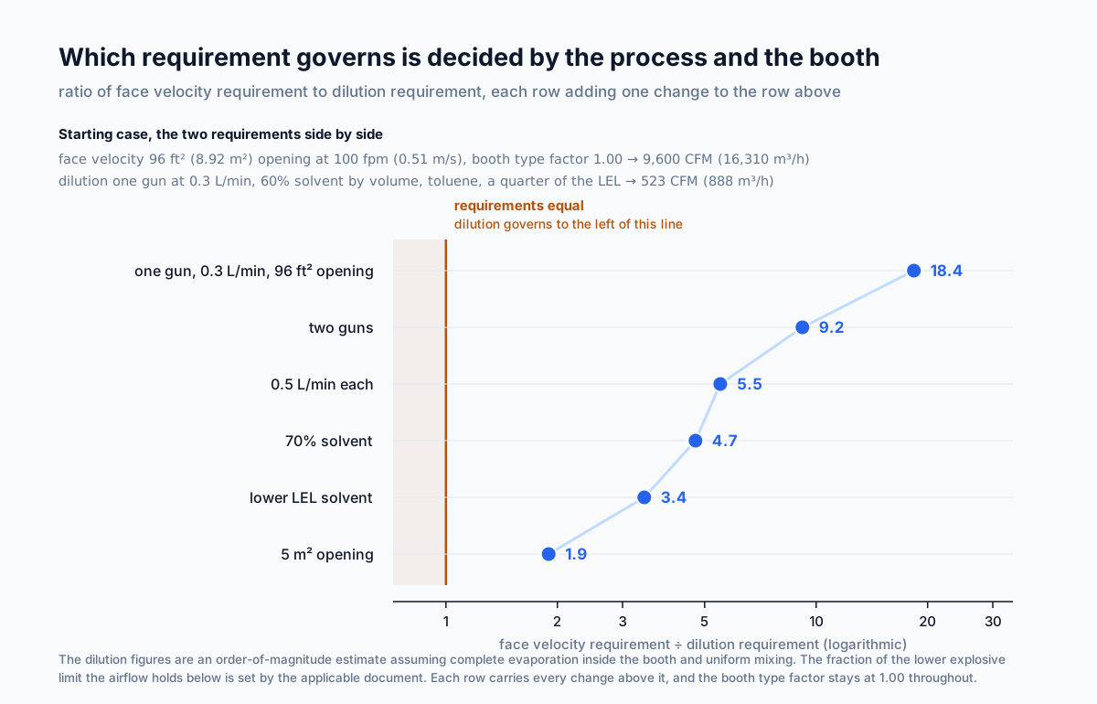
The two requirements are computed from disjoint sets of inputs. Their ratio is therefore not a property of spray booths in general but of a particular process in a particular booth, and it moves across more than an order of magnitude as the assumptions change.
The starting point, taking the imperial example on the calculator page:
A booth with a 96 ft² (8.92 m²) opening at 100 fpm (0.51 m/s)
requires 9,600 CFM (16,310 m³/h).
Dilution for one gun at 0.3 L/min with a solvent fraction of 0.6
requires 523 CFM (888 m³/h).
Ratio: 18.4.
How the ratio moves as the assumptions change, each line adding one change to the line above it:
Starting case                                       ratio 18.4
Two guns instead of one                                    9.2
0.5 L/min each instead of 0.3                              5.5
Solvent fraction 0.7 instead of 0.6                        4.7
A solvent of 0.8% limit instead of 1.1%                    3.4
The same spraying in a booth with a 5 m² (54 ft²)
  opening at 0.5 m/s                                       1.9
The ratio travels from eighteen to under two across six changes — every one of which sits inside ordinary practice. None of them is an extreme case, and none of them is a combination that would look unusual on a real installation.
Which variables decide the outcome:
On the dilution side: the spray rate, the number of atomisers, the
solvent fraction, the properties of the particular solvent, and the
fraction of the explosive limit the airflow has to hold below.
On the velocity side: the area of the working section and the
required velocity.
None of these quantities appears in both problems, which is why their
ratio obeys no general rule.
What follows for the calculation is that both requirements are computed separately for the process and the booth in question, and the larger is taken. An assumption about which will turn out larger does not substitute for the calculation, and a common impression that one of them usually dominates does not survive a change of assumptions.
The extremes are recognisable. A large booth with occasional hand touch-up sits well towards the face velocity requirement. A small booth serving a high-output automatic line sits towards the other. Between those two lies a region where the requirements are comparable and both have to be checked.
Per NFPA 33 and OSHA spray finishing provisions: the face velocity requirement and the vapour dilution requirement are computed from disjoint inputs, so which of them governs follows from the process and the booth together and has to be established by calculating both rather than assumed.
The Reference Section Is Not the Opening in Every Booth
The model applies a booth type factor to the same reference area for every configuration. The configurations differ not by how much air they need per unit of opening, but by which surface the air actually passes through.
How air moves in each arrangement:
Crossdraft booth: air enters through the opening or through a filtered
  wall facing it and travels horizontally through the working zone to
  the exhaust. The opening and the working section practically
  coincide.

Downdraft booth: air is supplied through the ceiling and moves
  downward around the work to extraction grilles in the floor. It does
  not pass through the opening at all. The opening serves to bring the
  work in, and the airflow crosses it rather than travelling through
  it.

Semi-downdraft booth: air follows a diagonal path from the ceiling at
  the front of the booth to extraction at the rear.
What follows from that:
For a downdraft booth the plane of the opening is not the section the
airflow passes through, and a result computed on opening area belongs
to a different quantity.
The applicable working section is determined by the booth design, and
the manufacturer's data states the basis adopted.
What the multiplier does:
The value 1.15 raises the result by fifteen percent relative to the
calculation on opening area.
That is a fixed screening allowance inside the calculation, not a
change to a different reference.
The difference between the two references can be a multiple rather
than a percentage, because the depth of a booth and the height of its
opening are only loosely related to each other.
The order of that divergence, on a booth of the size the metric example uses:
A booth with a 4.0 × 2.5 m opening has an opening area of 10.0 m²
(108 ft²).
The same booth at 7 m (23 ft) depth has a horizontal section of
28 m² (301 ft²), close to three times as much.
Which of the two forms the basis of the calculation is decided by the
airflow pattern, not by a multiplier.
For configurations where the flow does not pass through the opening, the value obtained on opening area is compared against the booth manufacturer's data, which states the basis adopted and the velocity that goes with it. A divergence between the two indicates a difference in which section the quantity refers to rather than an error in the arithmetic.
Per NIOSH descriptions of spray booth airflow patterns and ACGIH Industrial Ventilation: booth configurations differ in which surface the air passes through, so the opening area suits crossdraft arrangements while downdraft booths move air through a different section, and the applicable basis follows from the booth design rather than from a multiplier.
The Velocity Window Is Bounded at Both Ends
Most ventilation requirements have a floor and no ceiling. A spray booth has both — the upper bound exists because air moving too fast across the work damages the finish the booth was installed to protect.
The lower bound:
Insufficient velocity leaves part of the atomised paint in the booth
volume, from where it settles on the walls, the lighting and the work
itself, and reaches the operator's breathing zone.
The applicable documents set minimum values that differ by type of
operation and by booth construction, and for several configurations
they do not reduce to a single figure.
The upper bound:
Excessive velocity blows the atomised spray off its path and carries
paint past the work, which lowers the share of material deposited and
increases the load on the filters.
Turbulence at the surface of the work degrades film uniformity and
encourages defects.
What makes this problem unlike most others in ventilation:
In most ventilation problems raising the airflow improves the result
and is limited only by cost.
Here it degrades the result against one of the criteria, and the
acceptable region lies between two bounds.
What happens past the upper bound is worth following through, because the consequences return to the first requirement:
The share of paint reaching the work falls, and more material is
consumed for the same coating.
The filters load faster and the replacement interval shortens.
The dilution requirement rises, because more paint has to be sprayed
to achieve the same film.
Design values come from the applicable documents for the type of operation in question and from the booth manufacturer's data. Carrying a value adopted for one configuration across to another is not supported by either source.
Per OSHA spray finishing provisions and ACGIH Industrial Ventilation: booth velocity is bounded below by capture of overspray and above by disruption of the spray pattern, and the applicable values differ by type of operation and booth construction rather than following a single figure.
Makeup Air Is the Same Number Again, and It Has to Be Heated
Every cubic foot per minute the booth exhausts has to be replaced, and in a heating climate the cost of bringing that air to working temperature dominates everything else about the installation.
The balance is straightforward. Supply airflow equals exhaust airflow with a small offset, and that offset sets the direction of leakage between the booth and the shop.
The heating load:
Imperial: Q = 1.08 × CFM × ΔT        [BTU/hr]
Metric:   Q = ṁ × c_p × ΔT           [kW]
          ṁ = (m³/h × 1.2) / 3600    [kg/s]

1.08  = 60 min/hr × 0.075 lb/ft³ × 0.24 BTU/(lb·°F)
1.2   air density, kg/m³
1.005 specific heat of air, kJ/(kg·K)
ΔT    temperature rise across the makeup air unit, °F or K
For the two example booths:
9,600 CFM warmed from −1 °C to 21 °C (30 °F to 70 °F):
  Q = 1.08 × 9,600 × 40 = 414,700 BTU/hr (121.5 kW)

20,700 m³/h (12,183 CFM) warmed by 20 K (36 °F):
  ṁ = 20,700 × 1.2 / 3600 = 6.90 kg/s
  Q = 6.90 × 1.005 × 20 = 138.7 kW (473,300 BTU/hr)
The heating capacity of the makeup air unit serving a single spray booth is comparable to the space heating load of a medium-sized workshop and frequently exceeds it. The quantity follows directly from the exhaust airflow and rises with it linearly, so the choice between the two requirements on the airflow has an immediate cost consequence.
Recirculation is applied within narrow limits, because returning air from the booth would return the solvent vapour with it, which defeats the purpose of the ventilation. The applicable documents restrict recirculation from spray booths and state the conditions under which it is permitted.
What reduces the load:
Operating the booth at a reduced airflow between spraying cycles,
where the applicable requirements permit it.
Heat recovery from the exhaust, limited by the paint and solvent
carried in it.
Separating the spraying and curing modes, which run at different
airflows.
Per ACGIH Industrial Ventilation and spray finishing practice: exhaust from a spray booth has to be replaced by tempered makeup air, and the heating capacity that requires follows directly from the exhaust airflow, frequently exceeding the space heating load of the shop around it.
Filter Loading Moves the Operating Point Through the Shift
A booth collects overspray on filters that sit in the airflow path, so the resistance of the system rises through every working shift and the delivered airflow falls with it.
The mechanism is direct. The filters retain atomised paint, their resistance grows as it accumulates, and the fan moves along its characteristic towards a lower flow.
The order of magnitude:
The resistance of a clean filter and of one due for replacement
differs by a factor of several.
How far the airflow falls over that range depends on the steepness of
the fan characteristic at the operating point. The flatter the curve
there, the greater the loss.
Why this matters more here than in most systems:
Loading happens quickly, because the filter is collecting paint rather
than dust, and the replacement cycle is measured in days or weeks.
An airflow that has fallen below the design value degrades capture and
vapour dilution at the same time, so it affects both requirements at
once.
What the design responds with:
Selecting the fan for the loaded filter condition rather than the
clean one.
Fitting differential pressure monitoring across the filter with an
alarm on the replacement threshold.
Variable speed drive control that holds the airflow constant as the
resistance rises.
Verification follows the same logic. Airflow or velocity is measured at the actual condition of the filters rather than immediately after a change, because a reading taken on clean filters describes the best hour of the cycle rather than a representative one.
Per NFPA 33 and spray booth manufacturer practice: filter resistance rises as overspray accumulates, so fan selection is made for the loaded condition and airflow is verified in service rather than immediately after a filter change.
Transfer Efficiency Decides How Much Overspray There Is
The share of sprayed paint that reaches the work varies widely with the application method, and the remainder is both the overspray the filters collect and the solvent load the dilution requirement responds to.
Transfer efficiency is the fraction of sprayed paint deposited on the work. The rest becomes aerosol, and the filters collect it.
The spread across application methods:
Conventional high-pressure air atomisation gives the lowest share
transferred.
High-volume low-pressure guns give a noticeably higher share.
Electrostatic application gives the highest, because charged particles
are attracted to the work.
Airless application sits between them.
Specific values depend on the geometry of the work, the equipment
settings and the skill of the operator.
How that connects to the two requirements:
For a given quantity of coating deposited, higher transfer means a
lower spray rate, which means less solvent released and a smaller
dilution requirement.
The face velocity requirement does not depend on transfer efficiency
at all, because it follows from the geometry of the booth.
Changing the application method therefore moves the ratio between the
two requirements by acting on one of them only.
The filter side follows the same fraction. Everything that does not deposit on the work reaches the filters, and the replacement interval is inversely proportional to that share.
Per ACGIH Industrial Ventilation and coating practice: transfer efficiency varies substantially between application methods, and the fraction that does not reach the work becomes both the overspray load on the filters and the solvent load behind the dilution requirement.
Booth Pressure Sets Which Way Contamination Travels
The difference between supply and exhaust airflow decides whether air moves from the booth into the shop or the other way, and each direction has a consequence.
The two regimes:
Supply below exhaust: the booth is held at a slight negative pressure
  and air enters it from the shop through leakage paths.
  Vapour and aerosol do not escape.
  In exchange, unfiltered shop air with its dust enters the booth and
  spoils the finish.

Supply above exhaust: the booth is held at a slight positive pressure
  and air leaves it into the shop.
  The work is protected from shop dust.
  In exchange, a share of the vapour and aerosol reaches the shop.
What is chosen in practice follows from which of the two matters more. Booths where finish quality is decisive run at a slight positive pressure, with filtration of the supply air preventing dust ingress. Booths where containment is decisive run at a negative pressure. A number of designs run positive during spraying and negative during curing, switching between the two as the cycle changes.
The magnitude involved is small. The differential required is on the order of a few pascals, but it has to be maintained as the filter resistance changes through the shift, which is a control problem rather than a fan selection problem.
None of this follows from the airflow calculation. The model gives an exhaust quantity. The relationship between supply and exhaust is a separate design decision, set by the purpose of the booth and by the applicable requirements.
Per NFPA 33 and spray booth design practice: the balance between supply and exhaust determines the direction of leakage between booth and shop, and the choice between slight positive and slight negative pressure follows from whether finish quality or containment governs.
Air Changes and Velocity Answer Different Questions
Booth performance is specified as a velocity through the working section rather than as an air change rate, and comparing the two measures shows why the second misleads.
Air change rate = airflow / booth volume
For the booth in the imperial example:
Crossdraft booth, 12 × 8 ft opening, 40 ft (12.19 m) deep:
  Airflow 9,600 CFM, volume 3,840 ft³ (108.7 m³)
  Rate: 9,600 / 3,840 = 2.5 air changes per minute

A hypothetical case at half the velocity through twice the working
section, at the same volume:
  The airflow is unchanged, and so is the air change rate.
  The velocity through the working zone has halved.
What the comparison shows is that the air change rate does not distinguish which section the air passes through or at what speed. Two booths with identical air change rates can have substantially different velocities through the working zone, and capture is decided by the second quantity.
Velocity is what gets specified because capture of aerosol is determined by air movement in the spraying zone rather than by how many times per minute the whole booth volume is replaced. The two measures answer different questions, and only one of them is about capture.
The air change rate does have a use. Estimating the time to clear a booth after spraying, before personnel enter, is a question about the volume, and there the rate is the relevant quantity.
Per spray booth design practice: booth ventilation is specified by velocity through the working section rather than by air change rate, because the air change rate does not distinguish which section the air passes through or at what speed.
Worked Example: 9,600 CFM Across a 96 Square Foot Face
The scenario matches the imperial example on the calculator page.
Booth opening   12 × 8 ft (3.66 × 2.44 m)
Face velocity   100 fpm (0.51 m/s)
Booth type      Crossdraft, factor 1.00
Step 1. Opening area.
12 × 8 = 96 ft² (8.92 m²)
Step 2. Required ventilation rate.
96 × 100 × 1.00 = 9,600 CFM (16,310 m³/h)
Step 3. Category.
9,600 CFM sits inside the 5,000 to 14,999 band  → NORMAL
16,310 m³/h sits inside 8,495 to 25,484         → NORMAL
The bands agree across the unit toggle.
Step 4. The second requirement at the starting assumptions.
One gun at 0.3 L/min, solvent fraction 0.6, toluene:
  523 CFM (888 m³/h)
Ratio to the face velocity requirement: 18.4.
At these assumptions the face velocity requirement governs.
Step 5. How the conclusion moves at other assumptions.
Four guns at 0.5 L/min with a solvent fraction of 0.7 and a solvent
of 0.8% limit:
  Q = 523 × 4 × 1.667 × 1.167 × 1.375 = 5,592 CFM (9,501 m³/h)
The ratio falls to 1.72 and the two requirements converge.
A further rise in output moves control to dilution.
Step 6. Heating load of the makeup air unit.
Warming 9,600 CFM from −1 °C to 21 °C (30 °F to 70 °F):
  Q = 1.08 × 9,600 × 40 = 414,700 BTU/hr (121.5 kW)
Comparable to the space heating load of a medium-sized workshop.
Step 7. Air change rate, for comparison.
At 40 ft (12.19 m) depth the volume is 3,840 ft³ (108.7 m³) and the
rate is 2.5 air changes per minute.
The figure is given for comparison and is not a design criterion.
Step 8. What a different booth type would give.
A factor of 1.15 would give 11,040 CFM (18,757 m³/h), still inside
the NORMAL band.
For a configuration where the flow does not pass through the opening,
a different section forms the basis of the calculation, and the value
is compared against the manufacturer's data.
Step 9. Filter condition.
The airflow obtained applies to clean filters.
The fan is selected for the loaded filter condition, otherwise the
airflow will have fallen below the design value by the end of the
shift and both requirements will be affected at once.
Step 10. Result.
9,600 CFM (16,310 m³/h), NORMAL.
With one gun the face velocity requirement governs at a ratio of
18.4; with four guns at a raised output and a more volatile solvent
the ratio falls to 1.72.
The makeup air unit calls for about 121 kW (415,000 BTU/hr) of
heating capacity for winter operation.
Metric Example and the Downdraft Question
The scenario matches the metric example on the calculator page.
Booth opening   4.0 × 2.5 m (13.1 × 8.2 ft)
Face velocity   0.5 m/s (98 fpm)
Booth type      Downdraft, factor 1.15

Opening area:   4.0 × 2.5 = 10.0 m² (108 ft²)
Airflow:        10.0 × 0.5 × 3600 × 1.15 = 20,700 m³/h (12,183 CFM)
Category:       inside 8,495 to 25,484 → NORMAL
Checking that the two systems agree:
20,700 m³/h × 0.5886 = 12,184 ≈ 12,183 CFM
12,183 CFM sits inside 5,000 to 14,999 → NORMAL
The bands agree.
What the downdraft selection means for the result:
In such a booth air is supplied at the ceiling and moves downward to
extraction grilles in the floor, without passing through the opening.
The plane of the opening is therefore not the section the airflow
travels through.
The 1.15 multiplier raises the result by fifteen percent, which is a
screening allowance inside the calculation rather than a move to a
different basis.
The order of the divergence:
The horizontal section of a booth 7 m (23 ft) deep is 28 m²
(301 ft²), close to three times the opening area.
How far an airflow referred to that section differs from the value
obtained depends on the velocity adopted for it, which for downdraft
flow is generally lower.
The value is compared against the manufacturer's data, which states
the basis adopted and the velocity that goes with it.
The second requirement for the same case:
For one gun it is the same 888 m³/h (523 CFM), because it does not
depend on the dimensions of the booth.
Ratio to the model result: 20,700 / 888 = 23.3.
Under an intensive process the ratio falls in the same way as in the
imperial case.
Sensitivity to the size of the booth:
The same spraying in a booth with a 5 m² (54 ft²) opening at
0.5 m/s (98 fpm), on a crossdraft factor of 1.00, gives a face
velocity requirement of 9,000 m³/h (5,297 CFM) against an unchanged
dilution requirement.
The ratio falls from 23.3 to 10.1 for one gun and approaches unity
under an intensive process.
Per NIOSH descriptions of booth airflow patterns and manufacturer practice: a downdraft booth moves air through a horizontal section rather than through the opening, so a result computed on opening area belongs to a different reference and is compared against manufacturer data rather than adjusted by a multiplier.
Application Boundaries: Hazard, Process, Compliance
The scope of the model is an airflow estimated from an opening area, a face velocity and a booth type factor. The following sit outside that scope.
The vapour dilution requirement. Absent from the calculation, following from the spray rate and the solvent content of the coating, and depending on the process it may be the governing one of the two.
Hazardous area classification. Determined by the applicable documents and not part of the calculation.
The working section. The multiplier is applied to the opening area, while in several configurations the air passes through a different section defined by the booth construction.
The booth type factors. Screening allowances internal to the calculation rather than values taken from any code or standard.
Booth depth. Not among the fields, and for several configurations it takes part in defining the working section.
The upper velocity bound. Excessive velocity degrades finish quality and lowers transfer efficiency, and no field carries that limit.
The makeup air unit. The exhaust airflow requires an equal airflow of tempered supply air, whose heating capacity follows from it linearly.
Filter loading. Resistance rises through the shift and the airflow falls below the design value, affecting both requirements at once.
Pressure balance. The relationship between supply and exhaust is a separate design decision.
Transfer efficiency. It sets the spray rate needed to achieve a given coating, and through it the dilution requirement.
Compliance. The result does not demonstrate conformity with the requirements of any jurisdiction, and the category bands are indicative.
Per NFPA 33, OSHA spray finishing provisions and ACGIH Industrial Ventilation: estimating an airflow from opening area and face velocity is the scope of this model, while vapour dilution, hazardous area classification, the applicable reference section, makeup air, filter loading and pressure balance each require separate treatment.
Paint Booth Ventilation Calculator
Paint booth ventilation by face velocity: it multiplies the booth opening area by a target velocity and by a booth type factor, returning a preliminary exhaust airflow and a size band. That is one of two requirements a spray booth answers to, the other being dilution of solvent vapour to a stated fraction of its lower explosive limit, which follows from the spray rate rather than from the booth. Which of the two governs depends on the process and the booth together. A first-pass target, not a code compliance calculation.
Open Paint Booth Ventilation CalculatorStandards and References
- NFPA 33, Standard for Spray Application Using Flammable or Combustible Materials (National Fire Protection Association, current edition). Ventilation requirements for spray application operations, dilution of solvent vapour, electrical equipment and area classification, filter requirements and the interlocks between ventilation and spraying.
- OSHA 29 CFR 1910.94(c), Ventilation: Spray Finishing Operations (Code of Federal Regulations, Title 29, revised annually). Ventilation requirements for spray booths, including air velocities set by type of operation and booth configuration, and the requirement at 1910.94(c)(6)(ii) for a total exhaust volume sufficient to hold vapour concentration below a stated fraction of the lower explosive limit.
- OSHA 29 CFR 1910.107, Spray Finishing Using Flammable and Combustible Materials (Code of Federal Regulations, Title 29, revised annually). Construction and operation of spray booths, ventilation interlocks, electrical classification and the handling of residues.
- ACGIH, Industrial Ventilation: A Manual of Recommended Practice for Design (ACGIH, 30th edition 2019 and subsequent revisions). Design of spray booths, the calculation bases applied to different configurations, velocity selection and requirements on the uniformity of the airflow across the working section.
- NIOSH, Autobody Repair Shops: Control of Paint Overspray (National Institute for Occupational Safety and Health, engineering controls database, current edition), with related NIOSH publications on spray booth airflow. Descriptions of airflow patterns in booths of different configuration, including downdraft flow around the work to floor extraction.
- ANSI/AIHA Z9.7, Recirculation of Air from Industrial Process Exhaust Systems (American National Standards Institute and American Industrial Hygiene Association, current edition). The conditions under which return of air from process exhaust systems is permitted, and the monitoring that has to accompany it.
- ANSI/AIHA Z9.2, Fundamentals Governing the Design and Operation of Local Exhaust Ventilation Systems (American National Standards Institute and American Industrial Hygiene Association, current edition). General requirements on local exhaust systems, their commissioning and their periodic testing.
- International Fire Code, chapters on spray application of flammable finishes (International Code Council, current edition). Ventilation requirements, vapour dilution provisions and the arrangement of spray application areas.
- International Mechanical Code, sections on exhaust systems for spray finishing operations (International Code Council, current edition). Exhaust system construction, discharge arrangements and makeup air provisions for spray booths.
- NFPA 91, Standard for Exhaust Systems for Air Conveying of Vapors, Gases, Mists and Particulate Solids (National Fire Protection Association, current edition). Construction of the exhaust system carrying the booth airflow, including duct materials, cleanouts and discharge.
- Spray booth manufacturer data (current published catalogue data). Airflows, adopted velocities and calculation bases for crossdraft, downdraft and semi-downdraft configurations, together with filter characteristics and replacement thresholds.
FAQ
How much airflow does a spray booth need?
Per OSHA spray finishing provisions and ACGIH Industrial Ventilation: enough to satisfy two separate requirements. One is a velocity through the working section, which for a crossdraft booth is the opening area times the target velocity, giving 9,600 CFM (16,310 m³/h) for a 96 ft² (8.92 m²) opening at 100 fpm (0.51 m/s). The other is dilution of solvent vapour, which follows from the spray rate. The larger of the two governs.
Which of the two requirements governs?
Per NFPA 33 and OSHA provisions: it depends on the process and the booth together, and it has to be established by calculating both. The ratio between them moves across more than an order of magnitude with the spray rate, the number of guns, the solvent content and the size of the working section, so no general rule about which is larger holds across applications.
Why does a downdraft booth need a different basis?
Per NIOSH descriptions of booth airflow: because the air moves downward around the work to floor extraction rather than through the opening, so the opening is not the section the airflow passes through. The booth type factor in a screening model is an internal allowance rather than a change of reference, and the applicable basis comes from the booth design and the manufacturer's data.
Can the velocity be too high?
Per ACGIH Industrial Ventilation and spray finishing practice: yes. Air moving too fast across the work disrupts the spray pattern, carries paint past the part and increases the load on the filters. It also raises the dilution requirement indirectly, since more paint has to be sprayed for the same coating.
How much does the makeup air cost to heat?
Per the sensible heat relation: for 9,600 CFM warmed from −1 °C to 21 °C (30 °F to 70 °F), about 415,000 BTU/hr (121 kW), which commonly exceeds the space heating load of the shop the booth sits in. The requirement follows directly from the exhaust airflow and rises with it linearly.
Does filter loading change the delivered airflow?
Per NFPA 33 and manufacturer practice: yes, and faster than in most systems, because the filters collect paint rather than dust. A fall in airflow affects both requirements at once. Fan selection is made for the loaded condition, and airflow is verified in service rather than immediately after a filter change.
Should the booth run at positive or negative pressure?
Per NFPA 33 and booth design practice: it depends on which matters more. Slight positive pressure keeps shop dust out of the finish, slight negative pressure keeps vapour and overspray inside the booth. Some installations run positive during spraying and negative during curing.
Related Calculators
- Welding Fume Extraction Rate: capture by a hood at a distance from the source, where the variable is the gap to the work rather than the area of an enclosure (article).
- Fan Power Calculator: the power of the exhaust fan delivering the calculated airflow against the resistance of loaded filters.
- Duct Size Calculator: sizing of the booth exhaust duct carrying that airflow to discharge.
- Velocity Pressure Calculator: the velocity pressure that a velocity or airflow measurement in the booth or its ductwork is taken from.
- Air Changes Per Hour Calculator: the air change rate, applicable to estimating clearance time after spraying but not to specifying capture.
- CFM Calculator: airflow for the space as a whole, alongside the booth serving part of it.
- HVAC Heat Load Calculator: the heat load of the shop, against which the heating capacity of the booth makeup air unit is compared.
- Cooling Load Calculator: the cooling load on the booth supply air in a hot climate, where the makeup air has to be brought down rather than up.