Capture Without a Connection
A hose clamped over a tailpipe and the general ventilation of a workshop sit at two ends of a range. The first takes the contaminant through a seal, at the point it leaves the source, in a geometry fixed by the connection. The second takes it after it has spread through the whole volume and mixed with everything in it. A welding hood works between the two. It collects the fume before the room does, which is the advantage, but it collects across a gap rather than through a seal, and every difficulty in sizing one follows from that gap.
Connecting to a tailpipe settles the question of where the contaminant goes. It has one route, and the airflow needed follows from the volume of gas and the temperature it arrives at. A welding hood has no such certainty. The fume rises from an arc travelling along a joint, and the hood pulls at it from somewhere nearby. Whether the fume arrives depends on how hard the hood pulls at the place where the fume actually is, and that depends on how far the hood is from it.
Distance governs because of the way air reaches an opening. Air converging on a hood arrives from every direction across a hemisphere, and the surface of a hemisphere grows as the square of its radius. Doubling the distance from the hood to the weld spreads the same airflow across four times as much surface and drops the velocity at the weld to roughly a quarter. Restoring that velocity means multiplying the airflow by about four. Nothing else in the problem responds that steeply.
The calculator multiplies hood face area by a face velocity and divides by a derating factor. Each of the three is a defensible quantity, and their product describes fume arising in the plane of the hood opening rather than at a working distance from it. This article covers what distance does to the requirement, why the velocity in the published capture figures is a different quantity from the one the face-area product uses, and what dividing by a derating factor assumes about the fume that was missed. The vehicle exhaust article dealt with capture through a physical connection. This is capture across a gap.
Calculator Inputs: An Area, a Velocity, and an Allowance
Four numeric fields and a unit toggle, and the second and fourth of them carry the assumptions that the rest of this article unpacks.
Unit System. Imperial (ft, fpm, CFM) or Metric (m, m/s, m³/h). The category bands convert exactly, so a result keeps its classification when the toggle moves.
Hood Width and Hood Height [ft or m]. The dimensions of the hood opening, which is the plane air is drawn through, rather than the outside dimensions of the device. A typical extraction arm has an opening of 0.15 to 0.25 m (0.5 to 0.8 ft) across. A welding booth is larger by an order of magnitude in area.
Hood Face Velocity [fpm or m/s]. The target air velocity in the plane of the hood opening. This quantity is tied to the airflow by an identity: face velocity is airflow divided by opening area, so entering one is the same as entering the other. It is not the quantity that published capture velocity figures refer to, and the difference is the subject of a later section.
Design Derating Factor [%]. A design allowance for an installation that will not perform ideally. What this quantity is, and what it is not, is worked through further down.
The relation, written separately for each system:
Imperial: Q [CFM]  = (W_ft × H_ft × V_fpm) / (D / 100)
Metric:   Q [m³/h] = (W_m × H_m × V_m/s × 3600) / (D / 100)
The 3600 converts a flow per second into a flow per hour and belongs only to the metric form. In imperial the product of square feet and feet per minute is already cubic feet per minute.
The result categories:
LOW        below 300 CFM (510 m³/h)
MODERATE   300 to 799 CFM (510 to 1,359 m³/h)
HIGH       800 to 1,499 CFM (1,360 to 2,549 m³/h)
VERY HIGH  1,500 CFM (2,550 m³/h) and above

The thresholds convert exactly: 300 × 1.699 = 509.7, 800 × 1.699 = 1,359.2
and 1,500 × 1.699 = 2,548.5, so a result does not change band with the unit
toggle. The bands are indicative sizing ranges rather than limits set by any
regulatory requirement.
What is absent from the fields:
The distance from the hood to the weld, which governs the required
airflow more strongly than any quantity that is present.
Whether the opening is flanged, which changes the requirement by
about a quarter.
The air movement in the workshop.
The position of the hood relative to the rising thermal plume.
Distance Enters the Answer Squared
The airflow a hood needs is set less by its own size than by how far it stands from the fume, and the relation between the two is quadratic.
For an unflanged hood:
Q = V × (10X² + A)

Q   required airflow            m³/s or CFM
      typically 0.1 to 2 m³/s (200 to 4,000 CFM) for one hood
V   capture velocity at the point of fume generation
                                m/s or fpm
      0.5 to 1.0 m/s (100 to 200 fpm) for welding, higher where
      air movement is present
X   distance from the plane of the hood to the source
                                m or ft
      0.1 to 0.5 m (0.3 to 1.6 ft) for an extraction arm
A   area of the hood opening    m² or ft²
      0.02 to 0.3 m² (0.2 to 3 ft²) for arms and small hoods
The conditions the relation is written for:
An unflanged hood of round or rectangular opening with an aspect ratio
no greater than 1:5, and a distance within about 1.5 times the square
root of the face area.
Flanged hoods, slot devices and booths follow different relations, and
the expression is not a general formula for extraction devices.
Where the 10X² term comes from:
Air approaches the opening from across a hemisphere whose surface grows
as the square of the radius. Holding a velocity at a point at distance X
therefore costs airflow in proportion to that surface.
The factor of ten is empirical, and it relates the area of the hemisphere
to the area of the opening.
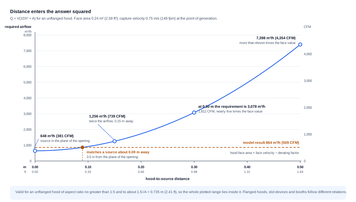
Worked through for the hood in the metric example on the calculator page, 0.24 m² (2.58 ft²) of opening holding 0.75 m/s (148 fpm) at the source:
X = 0      → 0.240 × 0.75 = 0.180 m³/s =   648 m³/h (  381 CFM)
X = 0.15 m → 0.465 × 0.75 = 0.349 m³/s = 1,256 m³/h (  739 CFM)
X = 0.20 m → 0.640 × 0.75 = 0.480 m³/s = 1,728 m³/h (1,017 CFM)
X = 0.30 m → 1.140 × 0.75 = 0.855 m³/s = 3,078 m³/h (1,812 CFM)
X = 0.50 m → 2.740 × 0.75 = 2.055 m³/s = 7,398 m³/h (4,354 CFM)
What the series shows:
Moving the hood back by 0.15 m (0.5 ft) very nearly doubles the
airflow, by a factor of 1.94.
At 0.30 m (1 ft), an ordinary working position for an extraction arm,
the requirement is nearly five times the value at the face.
At 0.50 m (1.6 ft) it is more than eleven times.
Neither the opening area nor the velocity produces anything like that
sensitivity.
The same character is written into a regulatory requirement rather than only into a design relation. OSHA 29 CFR 1910.252(c)(3)(i) requires 100 fpm (0.51 m/s) in the zone of welding with a freely movable hood at its most remote position from the work, and tabulates the airflow that calls for:
distance 4 to 6 in   (100 to 150 mm):   150 CFM (255 m³/h),   3 in duct
distance 6 to 8 in   (150 to 200 mm):   275 CFM (467 m³/h),   3½ in duct
distance 8 to 10 in  (200 to 250 mm):   425 CFM (722 m³/h),   4½ in duct
distance 10 to 12 in (250 to 300 mm):   600 CFM (1,019 m³/h), 5½ in duct

Taking the midpoints, the distance rises by a factor of 2.2 from 5 to
11 in and the airflow by a factor of 4.0, against 2.2² = 4.84 for a
purely quadratic dependence.
What that table does and does not confirm:
It confirms the character of the dependence. Airflow rises with roughly
the square of the distance, and this is stated as a requirement rather
than derived from a design relation.
It does not follow the expression above numerically, and it is not
meant to. The table is written for a specific movable-hood arrangement
with a 3 in wide flanged suction opening, which is a different geometry
from the unflanged hood the relation describes.
What follows for a design:
Bringing the hood 0.10 m (4 in) closer to the work saves more air than
any change of equipment.
The requirement to place a hood as near as practicable to the weld is
a direct consequence of the quadratic, not a matter of good practice.
Per ACGIH Industrial Ventilation and OSHA welding ventilation provisions for general industry: for an unflanged hood of moderate aspect ratio the airflow required to hold a given capture velocity at a distance follows Q = V(10X² + A), valid to about 1.5 times the square root of the face area, and published requirements for movable hoods show the same quadratic character across their tabulated distances.
Face Velocity and Capture Velocity Differ by an Order of Magnitude
The velocity in the plane of a hood opening and the velocity at the point where fume is generated are different quantities that share most of a name. At working distances they differ by a factor that runs from about five to about thirty, and published capture figures refer to the second of the two.
The two quantities:
Face velocity:    V_face    = Q / A
  An identity. Airflow divided by the area it passes through.
Capture velocity: V_capture = Q / (10X² + A)
  The air velocity at the point of fume generation, distance X away.
  The quantity published capture figures refer to.
Dividing one by the other removes the airflow and leaves a ratio that depends on geometry alone:
V_face / V_capture = (10X² + A) / A

Hood 2.0 ft² (0.186 m²) at X = 1.0 ft (0.30 m):   12.0 / 2.0   =  6.0
Hood 0.24 m² (2.58 ft²) at X = 0.30 m (1.0 ft):   1.14 / 0.24  =  4.75
Arm 200 mm dia, 0.031 m² (0.33 ft²), at 0.15 m:   0.256 / 0.031 =  8.2
Arm 200 mm dia, 0.031 m² (0.33 ft²), at 0.30 m:   0.931 / 0.031 = 29.7
The ratio grows as the opening gets smaller, which is why it is largest for exactly the device most commonly used on a welding bay. A 200 mm (8 in) extraction arm held 0.30 m (1 ft) from the arc induces about one thirtieth of its face velocity at the weld.
For the imperial example on the calculator page:
A = 2.0 ft², V_face = 150 fpm, hood 1.0 ft (0.30 m) from the arc:
  Q = 2.0 × 150 = 300 CFM, and with the 80% derating factor, 375 CFM
  V_capture = 375 / (10 × 1.0 + 2.0) = 375 / 12 = 31 fpm (0.16 m/s)
Against the requirement:
OSHA 29 CFR 1910.252(c)(3)(i) sets 100 fpm (0.51 m/s) in the welding
zone for the movable hood arrangement it describes.
The 31 fpm the model result holds at 1 ft is a third of that.
Reaching 100 fpm at the same distance takes
  Q = 100 × 12 = 1,200 CFM (2,039 m³/h)
which is 3.2 times the airflow the model returns, and lands in the
VERY HIGH band instead of MODERATE.
Why this is not an error in the model:
The model returns the airflow that produces a stated velocity in the
plane of the hood opening, and it does that correctly.
The difficulty is that face velocity and capture velocity are separate
quantities, so entering a published capture figure into a face velocity
field returns an airflow well short of what a source at a working
distance needs.
Per ACGIH Industrial Ventilation and OSHA 29 CFR 1910.252(c)(3)(i): hood face velocity and capture velocity at the point of generation are distinct quantities separated by the factor (10X² + A) / A, and NIOSH health hazard evaluations of welding extraction equipment measure the two separately, at the hood inlet and at the working distance in front of it, for that reason.
A Derating Factor Is an Allowance, Not a Captured Fraction
The model divides the airflow by a derating factor, and the name of that field carries engineering weight. The quantity expresses an allowance for an installation that will fall short of ideal, rather than the fraction of fume a hood physically intercepts.
What the division does:
Q_required = Q_base / (D / 100)

D = 80 multiplies the base airflow by 1.25
D = 75 multiplies it by 1.33
D = 50 multiplies it by 2.00
What reading it as a captured fraction would assume:
That the share of fume intercepted rises in proportion to airflow, and
that doubling the airflow doubles the share caught.
Why that holds only in part:
Raising the airflow raises the velocity everywhere in the field in
proportion, which does improve capture near the boundary of the region
the hood commands.
Fume carried outside that region by a cross-draft is not brought back
by drawing harder through the hood.
The intercepted share therefore approaches a ceiling set by geometry
and by air movement in the workshop rather than approaching unity.
Why the name matters:
A quantity called a capture efficiency invites the result to be read as
a guarantee that the corresponding share of fume is collected.
Called a design derating factor, it reads as what it is: an allowance
built into equipment selection.
The actual intercepted share is set by distance, geometry and air
movement, and it is established by measurement in the breathing zone
rather than calculated from an airflow.
What genuinely raises the intercepted share:
Reducing the distance, because it enters squared.
Flanging the opening, which blocks air drawn from behind the hood.
Removing cross-drafts near the workstation.
Repositioning the hood with respect to the thermal plume.
Every one of these acts on the geometry of the problem rather than on
the airflow.
Per HSE HSG258 and ACGIH Industrial Ventilation: capture effectiveness is governed by hood position, hood geometry and air movement in the workplace, so a derating divisor functions as a design allowance rather than as a relation between airflow and the fraction captured.
Cross-Drafts Compete With the Hood on Equal Terms
The velocities a hood induces at a working distance and the velocities ordinary air movement produces in a workshop are the same order of magnitude. That is why a hood which performs on a still morning fails when a door opens.
The orders of magnitude:
Air movement in a workshop:
  still conditions            0.1 to 0.25 m/s (20 to 50 fpm)
  ordinary work               0.25 to 0.5 m/s (50 to 100 fpm)
  near doors and fans         up to 1.0 m/s (200 fpm) and above

Capture velocity for welding:
  OSHA sets 100 fpm (0.51 m/s) in the welding zone for a movable hood,
  and published capture velocity tables select higher values where air
  movement is present.
What the overlap means:
Capture velocity exceeds typical air movement by a small factor rather
than by orders of magnitude, and with a door open it can be the smaller
of the two.
Fume is then carried past the hood regardless of the airflow through it.
How that enters the choice of velocity:
Published tables set capture velocity according to the air movement
present, so a shop with noticeable drafts calls for the upper part of
the range or above it.
Doubling the capture velocity doubles the airflow at unchanged geometry,
which is the expensive way to buy back a draft.
What costs less than more airflow:
Screens and partitions around the workstation, bringing local air
movement down to the still range.
Moving supply diffusers away from welding positions.
Coordinating the general ventilation with the extraction system, since
supply air aimed at a workstation destroys capture at it.
Why it is missed at commissioning:
Airflow is verified in quiet conditions, while the failure appears
during ordinary production, when doors stand open and other systems
run.
Per ACGIH Industrial Ventilation and HSE HSG258: capture velocities for welding are selected to exceed the air movement present in the workplace, and since ordinary workshop drafts fall in the same range, controlling that movement is often more effective than raising the airflow against it.
The Thermal Plume Helps Above and Hinders Beside
Welding produces a rising column of hot gas that carries fume upward without any help from the ventilation system. Whether that motion assists the hood or works against it depends entirely on where the hood sits.
The nature of the plume:
The arc heats both the air and the metal, and a rising column forms
above the weld.
Rise velocity near the source is in the region of 0.25 to 0.5 m/s
(50 to 100 fpm), and it falls with height as surrounding air is
entrained into the column.
A hood above:
The plume travels towards the hood and the two velocity fields add.
The capture velocity required is lower than for a source with no
motion of its own.
The limitation is that a hood above a welder collects fume that passes
through the breathing zone on its way up, which is why side and rear
positions are preferred in many applications.
A hood beside:
The plume crosses the direction of extraction, and the hood has to
overcome it.
The capture velocity required is higher, and the sensitivity to
distance is unchanged.
Downdraught through a bench grille:
The plume travels directly against the extraction.
The arrangement works at small distances and on work that does not
cover the grille.
What decides the position:
Hood position is chosen first so that fume does not pass through the
welder's breathing zone, and only then for the lowest airflow.
The two criteria frequently disagree.
The process moves both together:
Processes with high heat input produce a stronger plume and a higher
fume generation rate at the same time.
Wire feed speed and current settings move both quantities in the same
direction.
Per AWS F3.2 ventilation guidance for weld fume and ACGIH Industrial Ventilation: the thermal plume above a weld carries fume upward at a velocity comparable to typical capture velocities, assisting an overhead hood and opposing a side-draught one, while hood position is chosen first to keep fume out of the breathing zone.
A Flange Buys a Quarter of the Airflow Back
Adding a flat rim around a hood opening is the cheapest change available anywhere in this subject, and it cuts the airflow needed for the same capture velocity by about a quarter.
The mechanism:
An unflanged hood draws air from all directions, including the space
behind the plane of its opening, where the air carries no contaminant.
A flange blocks that path and redirects the inflow into the working
zone in front of the hood.
The size of the effect:
For a flanged hood the relation becomes
  Q = 0.75 × V × (10X² + A)
so the requirement is three quarters of the unflanged value for the
same geometry and the same capture velocity.
Applied to the metric hood at 0.30 m (1 ft):
Unflanged: 0.855 m³/s = 3,078 m³/h (1,812 CFM)
Flanged:   0.641 m³/s = 2,308 m³/h (1,358 CFM)
Saving:                    770 m³/h (  454 CFM)
The width required:
A flange of the order of the square root of the face area is enough for
the full effect.
For 0.24 m² that is about 0.5 m (1.6 ft) around the perimeter, and
widening it further adds very little.
What limits its use:
A flange increases the outside dimensions of the device, which matters
on a movable extraction arm that has to be positioned in tight work.
Booths and fixed hoods are less constrained, and flanging is usual
there. The OSHA movable-hood table assumes a flanged suction opening.
Flanging and closing the distance together:
Flanged hood at 0.20 m (0.66 ft):
  0.75 × 0.75 × 0.640 = 0.360 m³/s = 1,296 m³/h (763 CFM)
Unflanged hood at 0.30 m (1 ft):    3,078 m³/h (1,812 CFM)
The two measures together cut the requirement by more than half.
Per ACGIH Industrial Ventilation: flanging a hood opening reduces the airflow required for a given capture velocity to about three quarters of the unflanged value, with a flange width of the order of the square root of the face area giving the full effect.
The Device Ladder: From Booth to Torch
Welding extraction devices span two orders of magnitude in airflow, and the spread is explained almost entirely by the distance each one puts between its opening and the arc.
The ladder:
Welding booth: the work sits inside a volume and the fume does not
  leave it. Airflow follows from the velocity across the booth opening
  and runs to thousands of cubic metres per hour.

Canopy hood over a station: distance of the order of a metre. Airflow
  is large and capture is unreliable, because drafts act over the whole
  of that distance.

Extraction arm: 0.2 to 0.4 m (0.7 to 1.3 ft) when positioned properly.
  Airflow of one and a half to three thousand cubic metres per hour
  (900 to 1,800 CFM), depending on where it is left.

Downdraught bench: small distance, but the plume rises against the
  direction of extraction, and the work can cover the grille.

On-torch extraction: an opening a few centimetres from the arc.
  Manufacturer data gives 50 to 100 m³/h (30 to 60 CFM) per torch.
What the ladder shows:
The ratio between the airflow of a booth and that of an on-torch system
exceeds twenty to one, and the difference is distance.
A device sitting centimetres from the arc costs tens of cubic metres
per hour. A hood half a metre away costs thousands.
What is paid for that proximity:
On-torch extraction adds weight and bulk to the torch itself and can
disturb the shielding gas over the weld pool if the airflow is set too
high.
The airflow has to be tuned to the process rather than maximised.
How the choice is made:
By the size and shape of the work, and by how much the workstation
moves.
Large fabrications rule out a booth, long seams make repositioning an
arm impractical, and many shops end up running two or three device
types side by side.
Per ISO 21904 on equipment for capture and separation of welding fume and manufacturer data: extraction devices run from on-torch systems drawing tens of cubic metres per hour to booths drawing thousands, and the range follows almost entirely from the distance between the opening and the arc.
What Is in the Fume Decides the Target
The airflow needed to control welding fume depends on what the fume contains, because exposure limits for its constituents differ by orders of magnitude between materials.
What the fume is:
Metal and metal oxide particles formed by vaporisation at the arc and
condensation immediately afterwards.
Composition follows from the parent material, the filler and any
electrode coating or flux.
The constituents that set the requirement:
Manganese is present in most steels and most filler materials, and the
limits published for its respirable fraction sit well below those for
welding fume as a whole.
Hexavalent chromium forms when stainless steels are welded and is
regulated under a standard of its own, with its own limit and its own
control requirements.
Nickel, zinc from galvanised coatings and fluorides from fluxes each
carry their own values.
What that means for a calculation:
An airflow that controls fume adequately on carbon steel can be
insufficient on stainless, because the governing limit is far lower.
A check against total particulate does not establish sufficiency for
individual constituents.
The general principle:
Regulatory and research bodies recommend reducing exposure to welding
fume as far below the applicable limit as is reasonably practicable
rather than treating the limit as a target, and the classification of
welding fume as carcinogenic has reinforced that position.
Applicable values differ between organisations and jurisdictions and
are revised periodically, so the numbers that govern a given site are
the ones its own jurisdiction publishes.
What is verified on site:
Breathing-zone concentration of the specific constituents, rather than
the airflow at the extraction device.
Per OSHA hexavalent chromium provisions, NIOSH welding fume guidance and ACGIH threshold limit values: exposure limits for welding fume constituents differ by orders of magnitude between materials, and the applicable values depend on the jurisdiction.
The Fan Has to Deliver It Through a Loaded Filter
A welding extraction system draws through a filter that collects the fume it captures, and the resistance of that filter rises as it does its job. The airflow at the hood falls over the service interval even when nothing else changes.
What rises with time:
The resistance of the filter element increases as collected fume
accumulates in it.
The fan moves along its own characteristic towards lower airflow.
The order of magnitude:
Between a clean element and one due for cleaning or replacement, the
resistance differs by a factor of several.
How much airflow that costs depends on the slope of the fan
characteristic at the operating point: the flatter the curve there, the
larger the loss.
What cleaning restores:
Pulse cleaning with compressed air does not return the element to its
original resistance, because part of the collected fume is retained in
the structure of the medium.
Residual resistance climbs from cycle to cycle, and the element is
eventually replaced rather than cleaned.
The arm itself:
A flexible corrugated arm with articulated joints adds resistance that
depends on its position.
The same fan delivers different airflows with the arm folded and with
it extended.
What follows:
The design airflow belongs to a clean filter and one position of the
arm.
Verification is by measurement in service conditions rather than from
the equipment data sheet.
Periodic airflow checks belong in the maintenance regime alongside
element replacement.
Per HSE HSG258 and ISO 21904: filter resistance rises as collected fume accumulates and is not fully restored by cleaning, so the airflow delivered at the hood declines over the service interval and has to be verified periodically rather than assumed.
Worked Example: 375 CFM at the Hood Face
The imperial case on the calculator page, followed through to what the answer implies about where the hood has to be.
Hood opening        2.0 × 1.0 ft (0.61 × 0.30 m)
Hood face velocity  150 fpm (0.76 m/s)
Derating factor     80%
Step 1. Opening area.
2.0 × 1.0 = 2.0 ft² (0.186 m²)
Step 2. Base airflow at the face.
2.0 × 150 = 300 CFM (510 m³/h)
Step 3. Applying the design allowance.
300 / 0.80 = 375 CFM (637 m³/h)
Step 4. Category.
375 CFM falls inside 300 to 799      → MODERATE
637 m³/h falls inside 510 to 1,359   → MODERATE
The bands agree because the thresholds were converted exactly.
Step 5. What capture velocity the result holds at a working distance.
At 1.0 ft (0.30 m) from the plane of the opening:
  V_capture = 375 / (10 × 1.0 + 2.0) = 375 / 12 = 31 fpm (0.16 m/s)
Against the 100 fpm (0.51 m/s) OSHA requires in the welding zone for a
movable hood, this is short by a factor of three.
Step 6. What 100 fpm at that distance would cost.
Q = 100 × (10 × 1.0 + 2.0) = 1,200 CFM (2,039 m³/h)
Ratio to the model result: 1,200 / 375 = 3.2
The category moves from MODERATE to VERY HIGH.
Step 7. What distance the model result corresponds to.
Solving the relation at Q = 375 CFM and V = 150 fpm:
  375 / 150 = 2.5 ft² = 10X² + 2.0
  10X² = 0.5, X² = 0.05, X = 0.224 ft = 2.7 in (68 mm)
The result matches a source about seven centimetres from the plane of
the opening, which is extraction brought right up against the seam.
Step 8. What a flange changes.
For 100 fpm at 1.0 ft with a flanged opening:
  0.75 × 1,200 = 900 CFM (1,529 m³/h)
HIGH instead of VERY HIGH, for the cost of a flat rim.
Step 9. What closing the distance changes.
Flanged hood at 0.5 ft (0.15 m), holding 100 fpm:
  0.75 × 100 × (10 × 0.25 + 2.0) = 0.75 × 450 = 338 CFM (574 m³/h)
Halving the distance and flanging the opening together take the
requirement from 1,200 CFM to 338 CFM, a reduction of more than three
times.
Step 10. The result.
375 CFM (637 m³/h) by the model, MODERATE.
That airflow holds 150 fpm in the plane of the opening and about
31 fpm at one foot in front of it.
Holding 100 fpm at one foot takes 1,200 CFM unflanged or 900 CFM
flanged, and halving the distance with a flange brings it to 338 CFM.
Metric Example and the Distance the Result Implies
The metric case on the page, and the same question asked of it.
Hood opening        0.60 × 0.40 m (1.97 × 1.31 ft)
Hood face velocity  0.75 m/s (148 fpm)
Derating factor     75%

Area:         0.60 × 0.40 = 0.24 m² (2.58 ft²)
Base airflow: 0.24 × 0.75 = 0.18 m³/s = 648 m³/h (381 CFM)
Allowance:    648 / 0.75  = 864 m³/h (509 CFM)
Category:     510 to 1,359 → MODERATE
Consistency across the two systems:
864 m³/h × 0.5886 = 508.6 ≈ 509 CFM
509 CFM falls inside 300 to 799 → MODERATE
The classification survives the conversion.
The distance the result corresponds to:
864 / 3600 = 0.240 m³/s
0.240 / 0.75 = 0.320 m² = 10X² + 0.24
10X² = 0.080, X² = 0.008, X = 0.089 m (3.5 in)
The result matches a source about nine centimetres from the plane of
the opening.
The requirement at real distances, same hood and same capture velocity:
X = 0.15 m (0.5 ft): 1,256 m³/h (  739 CFM)  MODERATE
X = 0.20 m (0.7 ft): 1,728 m³/h (1,017 CFM)  HIGH
X = 0.30 m (1.0 ft): 3,078 m³/h (1,812 CFM)  VERY HIGH
X = 0.50 m (1.6 ft): 7,398 m³/h (4,354 CFM)  VERY HIGH
What the category is describing:
The model places this case in the middle band, while the same hood at
an ordinary working distance sits in the top one.
A band describes the size of an airflow rather than the adequacy of
capture, and the movement between bands here is caused by distance
alone.
The two examples together:
The imperial case implies about 0.07 m (2.7 in), the metric case about
0.09 m (3.5 in).
Both correspond to a source practically in the plane of the opening,
which on a welding bay means extraction brought right up to the work.
What that means in practice:
The airflow the model returns is sufficient only with the device close
against the seam.
A movable arm left at arm's length needs several times that airflow,
which is why such systems frequently fail to capture while delivering
the airflow they were specified for.
Per ACGIH Industrial Ventilation: the airflow returned by a face-area model corresponds to capture at the hood plane, and solving the distance relation backwards shows how close a source has to be for that airflow to be sufficient.
Application Boundaries: Geometry, Exposure, Compliance
The scope of the model is an airflow estimated from the area of a hood opening, a velocity across it and a design allowance. The following sit outside that scope.
Distance to the source. Absent from the calculation and more influential than anything in it, because it enters squared.
The two velocities. Area multiplied by velocity gives the velocity in the plane of the opening, while published capture figures refer to the point of fume generation, and at working distances the two differ by a factor between about five and thirty.
Hood geometry. Q = V(10X² + A) applies to an unflanged hood of moderate aspect ratio within about 1.5 times the square root of the face area. Booths, slot devices and on-torch extraction follow other relations.
Flanging. Cuts the requirement by about a quarter and does not appear in the model.
Air movement in the space. Comparable in magnitude to capture velocities and able to reduce capture to nothing regardless of the airflow.
The thermal plume. Its direction relative to the hood changes the capture velocity required.
The design allowance. A margin for imperfect installation rather than a physical relation between airflow and the fraction caught.
Fume composition. Limits for individual constituents differ by orders of magnitude, and adequacy for one contaminant does not establish adequacy for another.
System resistance. The filter, the arm and the ductwork determine the airflow actually delivered at the opening, and it declines as the filter loads.
Compliance. The result does not demonstrate conformity with the requirements of any jurisdiction, and the category bands are indicative.
Per ACGIH Industrial Ventilation and HSE HSG258: estimating an airflow from face area and face velocity is the scope of this model, while hood distance, hood geometry, workplace air movement, fume composition, system resistance and exposure verification each require separate treatment.
Welding Fume Extraction Rate Calculator
Welding fume extraction by source capture: it multiplies the hood face area by a face velocity and divides by a design derating factor, returning a preliminary airflow and a size band. The product of area and face velocity describes capture in the plane of the hood opening, so the result corresponds to a source close to the face. Where the weld sits at a working distance, the airflow needed to hold a given capture velocity at that point rises with the square of the distance. A first-pass target, not a local exhaust design.
Open Welding Fume Extraction Rate CalculatorStandards and References
- ACGIH, Industrial Ventilation: A Manual of Recommended Practice for Design (ACGIH, 30th edition 2019 and subsequent revisions). Airflow relations for hoods of different geometry, capture velocities selected by the air movement present, the effect of flanging, and the conditions each relation is valid within.
- HSE HSG258, Controlling Airborne Contaminants at Work: A Guide to Local Exhaust Ventilation (LEV), third edition (HSE Books, 2017). Design of local exhaust ventilation, commissioning, thorough examination and testing, and the maintenance regime a capture system depends on.
- HSE, Controlling the risks from welding (Health and Safety Executive, welding guidance, current edition). The priority of capture at the source for welding fume and the expectations placed on local exhaust ventilation at a welding position.
- OSHA 29 CFR 1910.252(c), Welding, Cutting and Brazing: Ventilation and Protection (Code of Federal Regulations, Title 29, revised annually). Ventilation requirements for welding in general industry, including the requirement for 100 fpm in the welding zone with a freely movable hood at its most remote position, and the table of airflow against distance quoted here, which assumes a 3 inch wide flanged suction opening.
- OSHA 29 CFR 1926.353, Ventilation and Protection in Welding, Cutting, and Heating, and 29 CFR 1926.57, Ventilation (Code of Federal Regulations, Title 29, revised annually). Ventilation provisions written for construction work; 1910.252(c) is the general industry counterpart.
- OSHA 29 CFR 1910.1026, Hexavalent Chromium (Code of Federal Regulations, Title 29, revised annually). Separate control requirements for hexavalent chromium, which welding on stainless steels generates.
- NIOSH Health Hazard Evaluation reports on welding local exhaust ventilation (National Institute for Occupational Safety and Health, continuing programme), including report 2019-0215-3371 on portable welding fume extractors. Field evaluations that measure velocity at the hood inlet and capture velocity at the working distance in front of it as separate quantities.
- NIOSH welding fume guidance (National Institute for Occupational Safety and Health, current publications). Reduction of exposure to welding fume as far as reasonably practicable, and control of individual constituents rather than total particulate alone.
- ACGIH Threshold Limit Values and Biological Exposure Indices (ACGIH, revised annually). Exposure values for welding fume constituents, including manganese, nickel and hexavalent chromium.
- AWS F3.2M/F3.2:2018, Ventilation Guide for Weld Fume, second edition (American Welding Society, 2018, superseding F3.2M/F3.2:2001). Industry guidance on ventilation for welding operations, including selection and positioning of extraction devices.
- ISO 21904-1:2020, Health and Safety in Welding and Allied Processes: Equipment for Capture and Separation of Welding Fume, Part 1: General Requirements (International Organization for Standardization, 2020), with ISO 21904-2:2020 on separation efficiency and ISO 21904-4:2020 on determining the minimum air volume flow rate of capture devices. Requirements for extraction equipment and the test methods behind the figures manufacturers publish.
- Manufacturer data for welding extraction equipment (current published catalogue data). Airflow ratings, working reach of extraction arms, filter element characteristics and the airflows quoted for on-torch extraction.
FAQ
How much airflow does welding fume extraction need?
Per ACGIH Industrial Ventilation: far more depends on how far the hood stands from the weld than on the hood itself. For an unflanged hood the requirement follows Q = V(10X² + A), so a hood 0.30 m (1 ft) from the arc needs several times the airflow of the same hood collecting at its own face. A face-area calculation returns the value for capture in the plane of the opening, which for a 0.24 m² (2.58 ft²) hood at 0.75 m/s (148 fpm) is 648 m³/h (381 CFM) against 3,078 m³/h (1,812 CFM) at 0.30 m.
Why does distance matter so much?
Per ACGIH Industrial Ventilation and OSHA 29 CFR 1910.252(c)(3)(i): because air converges on a hood opening from a hemisphere whose area grows as the square of the radius, so holding a velocity at a point costs airflow in proportion to that area. The OSHA table for movable hoods shows the same character, rising from 150 CFM (255 m³/h) at 4 to 6 in (100 to 150 mm) to 600 CFM (1,019 m³/h) at 10 to 12 in (250 to 300 mm) for the same 100 fpm (0.51 m/s) in the welding zone.
Is the velocity in the field the capture velocity?
Per ACGIH Industrial Ventilation and OSHA 29 CFR 1910.252(c)(3)(i): no. The product of face area and face velocity gives the velocity in the plane of the opening, while published capture velocity figures refer to the point where fume is generated. The two are related by (10X² + A) / A, which is 4.75 for a 0.24 m² (2.58 ft²) hood at 0.30 m (1 ft) and close to 30 for a 200 mm (8 in) extraction arm at the same distance. NIOSH health hazard evaluations of welding extractors measure the two quantities separately for that reason.
Does dividing by a derating factor recover the missing fume?
Per HSE HSG258 and ACGIH Industrial Ventilation: only in part. Raising the airflow raises the velocity throughout the field and improves capture near its boundary, but fume carried out of that field by a cross-draft is not recovered by drawing harder through the hood. The divisor works as a design allowance rather than as a relation between airflow and the fraction captured.
How much does a flange save?
Per ACGIH Industrial Ventilation: about a quarter of the airflow for the same capture velocity, since the flange blocks the air otherwise drawn from behind the plane of the hood, which carries no contaminant. A flange width of the order of the square root of the face area gives the full effect, and widening it further adds very little. The OSHA movable-hood table assumes a flanged suction opening for the same reason.
Why do drafts matter when the hood is running?
Per ACGIH Industrial Ventilation and HSE HSG258: because ordinary workshop air movement, in the region of 0.25 to 0.5 m/s (50 to 100 fpm) during normal work, sits in the same range as the capture velocities used for welding, and near open doors it exceeds them. Screening the workstation is frequently more effective than raising the airflow against the draft.
Does the same airflow suit stainless steel and carbon steel?
Per OSHA 29 CFR 1910.1026 and ACGIH threshold limit values: not necessarily. Welding stainless steel generates hexavalent chromium, which is regulated separately and carries an exposure limit far below that for welding fume in general, so an airflow adequate on carbon steel may not control exposure on stainless. The applicable limits depend on the jurisdiction, and verification is by breathing-zone measurement of the specific constituents.
Related Calculators
- Vehicle Exhaust Extraction: capture through a physical connection to the source, where distance does not appear as a variable at all (article).
- Fume Hood Face Velocity Calculator: velocity across the sash opening of a laboratory fume cupboard, where the source sits inside the enclosure and distance plays no part.
- Dust Collection System Sizing: capture of solid particulate from machining equipment, with transport velocities to maintain in the ductwork behind the hood.
- Fan Power Calculator: the power needed to move the calculated airflow against the resistance of the arm and the filter.
- Duct Size Calculator: sizing of the collecting duct where several welding positions are joined to one fan.
- Velocity Pressure Calculator: the velocity pressure that an airflow measurement in an arm or a duct is taken from.
- CFM Calculator: airflow for the workshop as a whole, alongside the capture system serving its welding positions.
- HVAC Heat Load Calculator: the heat load of the shop, including the heat that welding positions release into it.