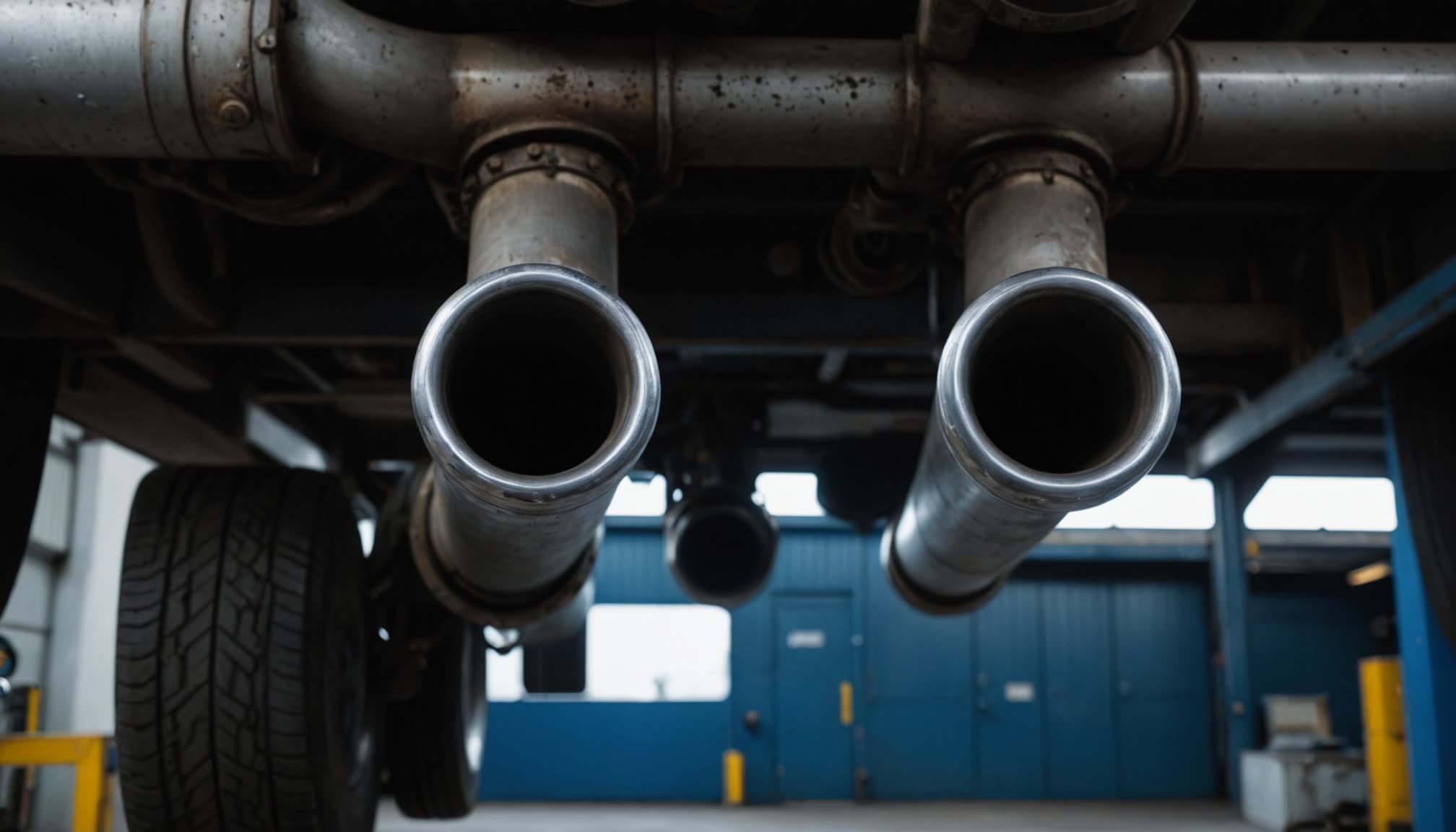
Capture Reverses the Question Dilution Answers
Dilution ventilation answers a question about a room. A contaminant is already loose in the air and mixed through the volume, and the calculation asks how much clean air has to pass through to hold its concentration at an acceptable level. Source capture asks something else entirely: how much air is needed to take the contaminant away before it mixes with anything at all.
The two questions produce airflows that differ by orders of magnitude for the same vehicle. Diluting the exhaust of one idling truck to an acceptable concentration in a workshop takes thousands of cubic feet per minute of general ventilation. Connecting a hose to the tailpipe of the same truck and drawing its exhaust straight outdoors takes several hundred. The contaminant never enters the room, so there is nothing to dilute.
What is paid for that advantage is a physical connection. Capture needs a hose on every tailpipe, which works in a repair bay where a machine stands still for an hour and fails completely where machines drive past. That division explains the layout of the whole subject. A parking garage is ventilated by dilution because nothing in it stays still long enough to be connected. A workshop is ventilated by capture because everything in it does. A fire station needs both: capture while the apparatus stands in the bay, and dilution for the ninety seconds when a vehicle pulls out with the hose released and the engine under load.
The calculator multiplies an assumed airflow per vehicle by a number of extraction points and by a concurrency factor. The multiplication is straightforward. The assumptions inside the first number are not, and the relationship between the last two is easy to get backwards. This article covers how much gas a tailpipe actually produces, why the capture rate has to exceed that volume several times over, and what a concurrency factor has to rest on before it is applied to a count of points. The parking garage article dealt with the dilution side of the same contaminant. This is the other half of the choice.
Calculator Inputs: A Flow per Vehicle That Carries the Assumptions
Three numeric fields and a unit toggle, and one of the three carries almost all of the engineering.
Unit System. Imperial (CFM) or Metric (m³/h). The category bands are converted exactly, so a result does not change classification when the toggle moves.
Exhaust Flow per Vehicle [CFM or m³/h]. The design extraction airflow required at one vehicle source. The page takes this figure from the user and points to extraction equipment manufacturer data, applicable local exhaust ventilation design criteria, or a project requirement. What sits inside it is the subject of the next two sections.
Number of Extraction Points / Bays [points]. The total number of vehicle extraction points included in the design, rather than the number of vehicles running at the moment under consideration. The distinction matters because of the field that follows it.
Design Diversity / Concurrency Factor [dimensionless]. The fraction of those points assumed to operate concurrently, greater than zero and up to 1.0, with 1.0 being the case where no reduction is justified.
The relation is a product:
Required = Flow_per_Vehicle × Point_Count × Concurrency
Where the assumptions sit:
The flow per vehicle carries the whole content of the calculation:
engine type, operating regime, gas temperature, and the way the
nozzle attaches to the tailpipe.
The other two fields are multipliers on it.
An error in the first field passes into the result one for one.
The result categories:
LOW        below 400 CFM (680 m³/h)
MODERATE   400 to 999 CFM (680 to 1,699 m³/h)
HIGH       1,000 to 1,999 CFM (1,700 to 3,399 m³/h)
VERY HIGH  2,000 CFM (3,400 m³/h) and above

The bands convert exactly: 400 × 1.699 = 679.6, 1,000 × 1.699 = 1,699
and 2,000 × 1.699 = 3,398, so the classification survives the unit
toggle. They are indicative sizing ranges rather than thresholds set
by any regulatory requirement.
What the calculation does not do: it does not establish the flow per vehicle, does not account for losses in the hose and the duct network, does not check a fan characteristic against system resistance, does not judge the quality of the connection at the tailpipe, and does not predict a concentration in anybody's breathing zone.
How Much Gas a Tailpipe Actually Produces
Before any judgement about capture airflow, the volume of gas leaving the tailpipe has to be known, and it is not a catalogue figure. It follows from the engine displacement, from the speed the engine turns at, from how completely the cylinders fill, and above all from the temperature of the gas, which expands it by a factor of two or more against the volume drawn in.
For a four-stroke engine:
V_exh = (D × N / 2) × VE × (T_exh / T_in)

D      displacement, litres          1.4 (small car) to 15 (heavy truck)
N      engine speed, rpm             600 to 900 idling,
                                     1,200 to 2,500 under load
VE     volumetric efficiency         0.7 idling to 0.95 under load
T_in   intake temperature, K         293 K (20 °C, 68 °F)
T_exh  exhaust temperature, K        523 to 873 K
                                     (250 to 600 °C, 480 to 1,110 °F)
The division by two is the four-stroke cycle: the engine induces its displacement once every two revolutions rather than once per turn.
Four cases, calculated from that relation:
Petrol car, 2.0 L at 800 rpm, VE 0.7, exhaust at 350 °C (623 K):
  (2.0 × 800 / 2) × 0.7 = 560 L/min at intake conditions
  × 623/293 = 1,190 L/min = 42 CFM (71 m³/h)

Diesel pickup, 6.7 L at 700 rpm, VE 0.85, exhaust at 250 °C (523 K):
  (6.7 × 700 / 2) × 0.85 = 1,993 L/min
  × 523/293 = 3,558 L/min = 126 CFM (214 m³/h)

Heavy truck idling, 13 L at 600 rpm, VE 0.9, exhaust at 300 °C (573 K):
  (13 × 600 / 2) × 0.9 = 3,510 L/min
  × 573/293 = 6,864 L/min = 242 CFM (411 m³/h)

The same truck under load, 1,500 rpm, exhaust at 450 °C (723 K):
  (13 × 1,500 / 2) × 0.9 = 8,775 L/min
  × 723/293 = 21,653 L/min = 765 CFM (1,300 m³/h)
These are calculated estimates under the assumptions stated beside each one, not manufacturer figures. A real engine's volumetric efficiency, its exhaust temperature and its idle speed all depend on the machine and on its state of tune, and any of the three moves the answer.
What the series shows:
The spread between a car idling and a heavy machine under load
exceeds eighteen to one: 765 / 42 = 18.2.
A single per-vehicle airflow applied across a mixed fleet is
therefore generous for part of it and short for the rest.
Engine speed and gas temperature move the result more than
displacement does, because both enter the same product and both
change by a factor of two or more between idle and load.
Per ACGIH Industrial Ventilation practice: exhaust volume follows from displacement, engine speed, volumetric efficiency and the thermal expansion of the gas, and the last of those roughly doubles the volume against intake conditions.
The Capture Rate Is Set by Cooling, Not by Gas Volume
The airflow drawn at a tailpipe nozzle is several times the volume of exhaust the engine produces, and the reason is not a safety margin. The gas has to be cooled before it can travel through a flexible hose, and cooling it is done by drawing in surrounding air.
The temperature problem:
Exhaust leaves the tailpipe between 250 and 600 °C
(480 to 1,110 °F) depending on the operating regime.
Flexible hose used in extraction systems carries temperature
limits which for rubber and polymer materials sit in the order
of 100 to 200 °C (210 to 390 °F), and higher for metallic hose.
The specific limit differs between materials and manufacturers
and is a product property rather than a general figure.
How the dilution happens at the nozzle:
The nozzle does not seal onto the tailpipe. The gap admits
surrounding air, which mixes with the exhaust and cools it before
it enters the hose. How much air has to be admitted follows from
an energy balance on that mixing.
Worked through for the idling heavy truck of the previous section:
Exhaust 242 CFM at 300 °C (573 K), density 353/573 = 0.616 kg/m³
Mass flow: 6.86 m³/min × 0.616 = 4.22 kg/min (9.30 lb/min)

Target mixture temperature 100 °C (373 K):
  m_air × (373 − 293) = m_exh × (573 − 373)
  m_air = 4.22 × 200 / 80 = 10.6 kg/min (23.4 lb/min)
  V_air = 10.6 / 1.204 = 8.8 m³/min = 311 CFM (528 m³/h)

Total mass flow: 4.22 + 10.6 = 14.8 kg/min
Mixture density at 373 K: 353/373 = 0.946 kg/m³ (0.059 lb/ft³)
Volume at the hose inlet: 14.8 / 0.946 = 15.6 m³/min
                        = 551 CFM (936 m³/h)
A note on the arithmetic: gas density is taken as 353/T for dry air at standard pressure, which gives 1.204 kg/m³ at 293 K. Exhaust gas differs in composition and in specific heat, so the figures above are an engineering estimate rather than an exact thermodynamic calculation.
Against a published order of magnitude:
ASHRAE gives a figure of the order of 0.28 m³/s per bay for
heavy diesel vehicle service facilities, which is
593 CFM (1,008 m³/h).

The calculation above, for a heavy truck idling with cooling to
100 °C, gave 551 CFM (936 m³/h). The two differ by about eight
percent, which for an estimate built on assumed values of
volumetric efficiency, exhaust temperature and hose limit is
close agreement.
What that agreement establishes, and what it does not:
A figure in the region of six hundred cubic feet per minute
belongs to heavy diesel equipment, not to every fleet.
For a car idling, the same method returns a substantially
smaller number, and applying one value across a mixed fleet
overstates the requirement for some vehicles while understating
it for others.
What follows from the calculation:
A capture rate of 551 CFM is more than twice the 242 CFM of
exhaust itself, and the ratio is set by the mixture temperature
the hose can accept rather than by any allowance for error.
A stricter hose limit calls for more entrained air and a larger
airflow. A metallic hose accepting a higher temperature calls
for less.
Per ACGIH Industrial Ventilation, ASHRAE Handbook provisions for vehicle service facilities, and manufacturer data for extraction hoses: the capture airflow at a tailpipe nozzle exceeds the exhaust volume by a factor of two or more, because ambient air is entrained to cool the gas below the temperature limit of the hose material.
Simultaneity Enters the Formula Twice
A count of vehicles running together and a fraction describing how often they run together are the same property written two ways. A model that multiplies both has to be explicit about which of the two the count is, because if it is not, concurrency gets applied to concurrency and the answer is neither a count nor an average of anything.
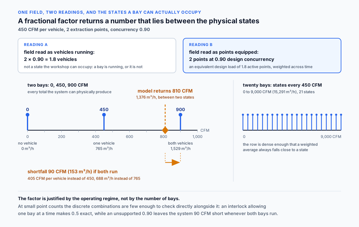
The page settles it by naming. The first field asks for the number of extraction points or bays included in the design, and the factor beside it asks for the fraction of those points assumed to operate concurrently. Read that way the product is coherent, and the page states the intermediate quantity outright in its worked example: two points at 0.90 is an equivalent design load of 1.8 active points, not a claim that 1.8 vehicles exist. Read the other way, with the count taken as vehicles already running, the same product would describe 1.8 simultaneously running vehicles out of two that are simultaneously running, which is the same idea applied twice.
The arithmetic that follows from the coherent reading:
450 × 2 × 0.90 = 810 CFM (1,376 m³/h)

The only totals two bays can physically produce at 450 CFM per
vehicle are 0, 450 and 900 CFM (0, 765 and 1,529 m³/h),
because a bay is connected and running or it is not.
810 CFM is none of them.
That is not a defect in the arithmetic. It is what a weighted average looks like on a scale of discrete states — the reason the result has to be read as a design load rather than as a condition the workshop occupies.
The shortfall if both bays do run:
A system delivering 810 CFM with both vehicles connected supplies
405 CFM to each instead of 450, which is 688 m³/h instead of 765.
The shortfall is 90 CFM (153 m³/h) across the system and
45 CFM (76 m³/h) at each nozzle.
Airflow missing at the nozzle is exhaust that stays in the room.
What the reading changes at the keyboard:
For a ten-bay workshop where two bays are typically in use, the
entry is ten points with a factor that reflects that pattern,
not two points at a factor of 1.0.
The two entries return different numbers, and which one is meant
has to be settled before the calculation rather than after it.
Per ACGIH Industrial Ventilation practice: a concurrency factor and a count of simultaneous vehicles describe the same property, so a model that takes both requires its count to be the number of extraction points rather than the number of vehicles running.
What Justifies a Concurrency Factor Is the Operating Regime
A concurrency factor below unity is defensible when something limits how many points can run together. The limitation has to be identified, and it is not inferred from the number of bays.
What supports a factor:
An interlock that physically permits only a limited number of
points to draw at once.
A work schedule under which bays are occupied in sequence.
A control strategy that apportions airflow between points and
prevents all of them opening together.
A survey of an operating facility recording actual concurrency
over a representative period.
What does not support one:
The number of bays by itself. Two points without an interlock run
together as readily as they run in sequence.
A designer's expectation about how busy the facility will be,
unsupported by any of the circumstances above.
A factor at a small point count, properly supported:
A two-bay workshop fitted with an interlock allowing one bay to
draw at a time is correctly calculated at a factor of 0.5:
  450 × 2 × 0.5 = 450 CFM (765 m³/h),
which equals the airflow of one point and coincides exactly with
a state the system can occupy.
The justification is the interlock, not the bay count.
The extra check that small counts make possible:
With two or three points the number of combinations is small, and
each one can be enumerated directly.
The airflow for the worst combination the system permits is then
compared against the result the factor produced.
Where the worst case exceeds it, selection follows the worst case.
At large point counts enumeration stops being practical, and the
factor remains the working method.
What the character of the facility settles on its own:
A test bay running a test programme operates at a factor of 1.0
whatever its point count.
A fire station is designed for simultaneous startup of the whole
fleet for the same reason.
Per ACGIH Industrial Ventilation and HSE HSG258: a concurrency factor requires a stated basis such as an interlock, a work schedule, a control strategy or a survey of actual operation, and at small point counts the discrete worst-case combinations are few enough to check directly alongside it.
Capture Against Dilution: Two Orders of Magnitude
The same vehicle controlled by capture and by dilution produces airflow requirements that differ by a factor of tens, and that gap is the entire economic argument for source capture.
For one vehicle:
Capture at the tailpipe: of the order of 450 CFM (765 m³/h).

Dilution in the room: exhaust carries carbon monoxide, and the
airflow follows from its emission rate divided by the allowable
concentration rise, which is the subject of the parking garage
article. For one machine running in a workshop the dilution
requirement runs into thousands of cubic feet per minute, and in
a large space with a tight target the gap against capture
approaches two orders of magnitude.
Where the difference comes from:
Capture handles the gas at its original concentration, which is
one hundred percent exhaust.
Dilution handles the same contaminant after it has mixed with the
room and reached parts per million.
The ratio of the two airflows is roughly the inverse of the ratio
of the two concentrations.
Why dilution is used at all:
Capture requires a physical connection to every vehicle. Where
vehicles drive rather than stand, no connection is possible and
dilution is the only remaining control. Hence the division of the
subject: garages and tunnels are ventilated by dilution, repair
bays and test cells by capture.
Where both are needed:
A fire station captures at the standing apparatus and still needs
general ventilation for the moments of departure, when the hose
has released and the engine is running under load.
A repair workshop needs dilution for vehicle movements between
bays, and for the minutes before a nozzle goes on and after it
comes off.
Capture reduces the dilution requirement. It does not remove it.
Per HSE HSG258 and ACGIH Industrial Ventilation: source capture achieves control with airflow an order of magnitude below dilution for the same source, because it removes the contaminant at its original concentration rather than after mixing with room air.
The Hose Is Where the Airflow Goes Missing
The airflow a fan is rated for and the airflow delivered at the nozzle are different numbers. In a hose system the difference is dominated by a component that anybody can change in a second and almost nobody rechecks afterwards.
What creates the resistance:
Flexible hose with a corrugated bore carries resistance several
times that of smooth duct of the same diameter.
Hose length enters the loss linearly.
Diameter enters it to a high power: reducing a hose from six to
four inches (150 to 100 mm) at the same airflow multiplies the
loss several times over.
Bends, kinks and the turns still on the reel add local losses.
The order of magnitude:
Corrugated hose commonly carries two to three times the loss of
smooth duct of the same diameter and length at the same airflow.
Leaving unused hose coiled on the reel does not remove its
resistance: the air passes through the whole length whether it is
run out or not.
What that does to the airflow:
A fan operates where its characteristic crosses the system
resistance curve. Added resistance moves that intersection towards
lower flow.
A system commissioned at 450 CFM (765 m³/h) on a short hose can
deliver appreciably less once the hose length doubles, and how
much less depends on how steep the fan curve is at that point.
What to verify:
Airflow is measured at the nozzle rather than read off the fan
rating.
The measurement is taken with the hose in the position it is used
in, including whatever remains on the reel.
Hose length changes during the life of a facility, so a system
that met its design airflow at commissioning does not necessarily
still meet it.
Per HSE HSG258 and ACGIH Industrial Ventilation: flexible corrugated hose carries substantially more resistance than smooth duct of the same diameter, and the delivered airflow at the nozzle has to be measured in the configuration actually used rather than taken from the fan rating.
Connection Quality Decides Whether Any of This Matters
Every number in the calculation assumes the exhaust enters the nozzle. A poor connection at the tailpipe sends a share of it into the room instead — and no amount of airflow at the fan changes that.
What breaks the connection:
A nozzle whose diameter does not match the tailpipe it is put on.
Worn seals and damaged nozzle lips.
Vertical and inclined stacks, which need their own adaptors.
Twin exhaust systems, where a single nozzle covers one pipe and
leaves the other discharging into the bay.
What happens when the fit is poor:
Part of the exhaust escapes into the room before it reaches the
nozzle. The share depends on the geometry of the gap and on the
ratio between capture airflow and exhaust volume.
Raising the fan airflow compensates for a poor fit in part. It
does not cure it.
Why the airflow reading will not reveal it:
Measuring airflow in the hose shows what the system is moving,
not what share of the exhaust it intercepted.
A system can read its design airflow while a noticeable fraction
of the exhaust goes into the workspace.
Confirming capture calls for measurement of concentration where
people breathe, not airflow alone.
What is done about it in practice:
Nozzles are selected against the actual fleet, including the
awkward exhaust configurations in it.
Nozzle condition goes into the maintenance schedule for the
system rather than being left to inspection by eye.
Breathing-zone concentrations are measured periodically, and not
only when something has changed.
Per HSE guidance on exhaust fumes in motor vehicle repair and HSG258: capture effectiveness depends on the seal at the tailpipe, and a system delivering its design airflow can still release a significant fraction of the exhaust into the workspace if the connection is poor.
Fire Stations Size for a Case That Lasts Ninety Seconds
A fire station is the application where capture matters most and where the design case looks least like normal operation. Every vehicle starts at once, runs under load, and leaves inside a minute or two.
What sets this case apart:
Concurrency is total: the alarm starts every appliance in the
building at the same moment.
Engines run under load rather than at idle, which multiplies both
the exhaust volume and its temperature.
The duration is short, of the order of one to two minutes from
start to departure.
The connection releases as the vehicle moves, so the last seconds
of exhaust discharge into the bay.
What that means for the calculation:
The concurrency factor is 1.0, because partial occupancy does not
describe the design case.
The flow per vehicle is taken for the loaded condition rather than
for idle, which by the arithmetic of Section 4 is several times
larger.
An automatic release system is needed, triggered as the vehicle
begins to move.
General ventilation is needed in addition, for the period after
the nozzle has released.
On the requirements themselves:
Fire service occupational health standards address exhaust
capture in apparatus bays. Which provisions apply, and in which
edition, is determined by the jurisdiction and by what that
jurisdiction has adopted, and the relevant text in North America
has recently been consolidated into a single responder health and
safety standard.
Why the stakes are higher here than in a workshop:
Personnel are inside the building at the moment of startup and
walk through the exhaust plume on their way to the apparatus.
Brief exposure is still exposure, and concentrations during those
seconds are high.
Per NFPA 1500 and fire service occupational health practice: apparatus bays call for source capture sized for simultaneous startup under load with automatic release, and the applicable provisions depend on the jurisdiction and the edition adopted.
Diesel Particulate Changed the Standard of Care
The case for capturing exhaust rather than diluting it strengthened considerably once diesel exhaust was classified as carcinogenic, because a carcinogen has no threshold below which exposure is comfortably acceptable.
What changed:
The International Agency for Research on Cancer classified diesel
engine exhaust as carcinogenic to humans in 2012, in the
evaluation published as Monograph Volume 105.
For carcinogens the accepted approach is reducing exposure as far
as is reasonably practicable, rather than holding it below a
threshold value.
Why that changes the choice of method:
Dilution lowers a concentration and leaves the contaminant in the
air of the room.
Capture removes it before mixing, and what remains is governed by
leakage at the connection alone.
Under a reduce-as-far-as-practicable duty the second is preferred
wherever it can be applied.
What separates particulate from gases:
Carbon monoxide dilutes and is carried out, and its concentration
follows the ventilation rate closely.
Particulate settles on surfaces and is resuspended by movement,
so exposure continues after the source has been switched off.
The practical consequence:
Workshops working mainly on diesel equipment need capture even
where a calculation on carbon monoxide alone suggests general
ventilation would be sufficient.
A check against one contaminant does not demonstrate adequacy
against another.
Per the IARC classification of diesel engine exhaust and occupational hygiene practice: control of a carcinogen follows the principle of reducing exposure as far as reasonably practicable rather than holding it below a threshold, which favours capture over dilution wherever capture is feasible.
Worked Example: 450 CFM per Vehicle Across Two Bays
The scenario matching the Imperial example on the page:
Exhaust flow per vehicle   450 CFM (765 m³/h)
Extraction points          2
Concurrency factor         0.90
Step 1. Airflow before the factor.
450 × 2 = 900 CFM (1,529 m³/h)
Step 2. Applying the factor.
900 × 0.90 = 810 CFM (1,376 m³/h)
Equivalent design active points: 2 × 0.90 = 1.8
Step 3. Classification.
810 CFM falls inside 400 to 999 → MODERATE
1,376 m³/h falls inside 680 to 1,699 → MODERATE
The categories agree, which follows from the exact conversion
of the band edges.
Step 4. What fleet a 450 CFM per vehicle figure describes.
By the method of Sections 4 and 5, a figure of 450 CFM sits below
the 551 CFM (936 m³/h) a heavy truck at idle needs once entrained
cooling air is counted, and well above what a car at idle needs.
It describes light to medium duty rather than heavy diesel
equipment, for which the published order of magnitude is
593 CFM (1,008 m³/h), and the same truck under load needs
substantially more again.
Step 5. What the 810 CFM result is.
The physical states available to two points are 0, 450 and 900 CFM.
810 CFM is an equivalent design load of 1.8 active points, which
is a weighted average and coincides with none of the three.
Step 6. The simultaneous case.
With both vehicles connected, a system built for 810 CFM delivers
405 CFM to each nozzle instead of 450.
The deficit is 45 CFM (76 m³/h) at each point and 90 CFM
(153 m³/h) across the system, which is 1 − 0.90 of the full
requirement.
Step 7. What would justify 0.90 across two bays.
A factor below unity needs a basis: an interlock, a schedule, a
control strategy or a survey. With two bays and none of those
present, simultaneous use is ordinary, and selection proceeds at
a factor of 1.0, which is 900 CFM (1,529 m³/h).
That result stays inside the MODERATE band, and it is eleven
percent above the previous figure: 900 / 810 = 1.111.
Step 8. Losses in the hose.
Both figures apply at the nozzle. The fan is selected to deliver
that airflow against the full system resistance, including the
hose in its working position.
A fan characteristic quoted at free discharge does not describe
operation against that resistance.
Step 9. What to check after commissioning.
Airflow is measured at the nozzle with the hose arranged as it is
actually used.
The quality of the connection is checked separately, because
achieving the design airflow does not demonstrate that the
exhaust is being captured.
Step 10. The result.
810 CFM (1,376 m³/h) from the model, MODERATE.
For equipment selection with no basis established for the factor,
take 900 CFM (1,529 m³/h), which covers both points running.
Verify the per-vehicle figure against the actual fleet and against
the temperature limit of the hose in use.
Metric Example and the Whole-Vehicle Scenarios
The scenario matching the Metric example on the page:
Exhaust flow per vehicle   700 m³/h (412 CFM)
Extraction points          2
Concurrency factor         0.85

700 × 2 = 1,400 m³/h (824 CFM)
1,400 × 0.85 = 1,190 m³/h (700 CFM)
Category: inside 680 to 1,699 → MODERATE
Consistency across the unit systems:
1,190 m³/h × 0.5886 = 700 CFM
700 CFM sits inside 400 to 999 → MODERATE
The two systems return the same category, since 1.699 and 0.5886
are reciprocal to four figures: 1.699 × 0.5886 = 1.0000.
The whole-vehicle states:
No vehicle running:      0 m³/h
One vehicle running:   700 m³/h (412 CFM)
Both running:        1,400 m³/h (824 CFM)
The model result of 1,190 m³/h lies between the second and third.
The shortfall in the simultaneous case:
1,400 − 1,190 = 210 m³/h (124 CFM) across the system
105 m³/h (62 CFM) at each point
Each nozzle receives 595 m³/h (350 CFM) instead of 700,
which is eighty-five percent of the design figure.
Comparing the two examples:
The Imperial case at 0.90 leaves a ten percent shortfall.
The Metric case at 0.85 leaves fifteen.
The shortfall equals one minus the factor in both, because with
two points the simultaneous case is the complete state.
The same two points with a basis for the factor:
Fitted with an interlock allowing one point at a time, the pair is
calculated at 0.5:
  700 × 2 × 0.5 = 700 m³/h (412 CFM),
which equals the airflow of a single point and coincides with a
state the system can occupy.
Here the factor expresses a restriction rather than an average,
and the result matches the worst case the system permits.
How the picture changes with more points:
At ten points of 700 m³/h each, a factor of 0.85 returns
5,950 m³/h (3,502 CFM), while all ten running together need
7,000 m³/h (4,120 CFM).
A factor at that scale rests on a survey or on a documented
schedule, and enumerating every combination of ten points stops
being a useful exercise.
Per ACGIH Industrial Ventilation: at two extraction points the shortfall against simultaneous operation equals one minus the concurrency factor, and a factor is defensible when an interlock or a documented operating regime limits how many points run together.
Application Boundaries: Pressure, Exposure, Compliance
The model estimates a total capture airflow from a per-point figure and a point count. Everything below sits outside it and needs its own treatment.
The flow per vehicle. Set by the fleet, the operating regime, the gas temperature and the temperature limit of the hose, and supplied to the model from outside it.
What the point count means. A count of running vehicles and a fraction of simultaneous use describe one property, so the result depends on which of the two is entered in the first field.
The basis for the factor. A value below unity requires an interlock, a schedule, a control strategy or a survey, and none of those circumstances enters the arithmetic.
System resistance. Losses in the hose, the reel, the ductwork and any filtration decide what airflow the fan actually achieves.
Fan selection. Made at the intersection of the fan and system characteristics rather than at free discharge.
Connection quality. The share of the exhaust that enters the nozzle depends on the fit at the tailpipe and is not part of the calculation.
Breathing-zone concentration. Airflow does not demonstrate that exposure is controlled; measurement where people breathe does.
Transient conditions. Startup and departure produce conditions unlike steady operation, and in fire stations those transients are the design case.
Discharge and cleaning. Discharging outdoors carries requirements on the discharge point, and any filtration added upstream of it adds resistance to the system.
Compliance. The result does not establish conformity with the requirements of any jurisdiction, and the category bands are indicative sizing ranges rather than regulatory thresholds. Requirements for exhaust capture differ between jurisdictions and between types of facility.
Per HSE HSG258 and ACGIH Industrial Ventilation: estimating a total capture airflow from a per-point figure is the scope of this model, while establishing that figure, the basis for any concurrency factor, system resistance, fan selection, connection quality, breathing-zone exposure and compliance each require dedicated assessment.
Vehicle Exhaust Extraction Calculator
Vehicle exhaust extraction by source capture: it multiplies an assumed airflow per vehicle by a point count and by a concurrency factor, returning a total capture rate and a preliminary size band. The per-vehicle figure carries the engineering, since it follows from engine displacement and speed, from the temperature of the gas, and from the ambient air entrained to cool it below the hose limit. A factor below unity needs a stated basis such as an interlock or a documented operating regime. A first-pass airflow target, not a system design.
Open Vehicle Exhaust Extraction CalculatorStandards and References
- HSE HSG258, Controlling Airborne Contaminants at Work: A Guide to Local Exhaust Ventilation (LEV), third edition (HSE Books, 2017). Design of local exhaust ventilation, commissioning, thorough examination and testing, and the maintenance regime that keeps a capture system working.
- HSE, exhaust fumes in mechanical repair (Health and Safety Executive, motor vehicle repair guidance, updated 2025). Control of exhaust fumes in repair premises, the limits of catalytic converters on cold and intermittently run engines, and tailpipe extraction as the expected control.
- HSE HSG187, Control of Diesel Engine Exhaust Emissions in the Workplace, third edition (HSE Books, 2012). Good practice for controlling exposure to diesel exhaust emissions in specific workplace situations, including vehicle repair premises.
- ACGIH, Industrial Ventilation: A Manual of Recommended Practice for Design (ACGIH, 30th edition 2019 and subsequent revisions). Design of capture systems, capture velocities, resistance of flexible hose, fan selection against system characteristics, and the treatment of concurrency in multi-point systems.
- ASHRAE Handbook, HVAC Applications, chapter on enclosed vehicular facilities (ASHRAE, 2023 volume). Ventilation of vehicle repair and service facilities, including the order-of-magnitude capture airflow per bay quoted here for heavy diesel service.
- ANSI/ASHRAE Standard 62.1, Ventilation and Acceptable Indoor Air Quality (ASHRAE, 2022 edition). Requirements for vehicle repair and service spaces, including direct connection to the exhaust system where engines are run indoors. The standard does not set the per-vehicle airflow used in this model.
- OSHA 29 CFR 1926.57, Ventilation (Code of Federal Regulations, Title 29, revised annually). Local exhaust ventilation requirements written for construction work, cited here for the general principle of removing contaminants at the source rather than as the standard governing a service bay.
- NFPA 1500, Standard on Fire Department Occupational Safety, Health, and Wellness Program (NFPA, 2021 edition), whose provisions have been consolidated into NFPA 1550, Standard for Emergency Responder Occupational Safety, Health, and Wellness (NFPA, 2024). Exhaust capture in apparatus bays, subject to the edition adopted in the jurisdiction.
- IARC Monographs on the Evaluation of Carcinogenic Risks to Humans, Volume 105, Diesel and Gasoline Engine Exhausts and Some Nitroarenes (International Agency for Research on Cancer, 2014; classification announced 2012). The evaluation classifying diesel engine exhaust as carcinogenic to humans, and its consequences for control practice.
- NIOSH Health Hazard Evaluation reports on vehicle exhaust capture (National Institute for Occupational Safety and Health, continuing programme). Evaluations at vehicle service and fire service facilities, including measured performance of installed capture systems.
- Manufacturer data for exhaust extraction equipment (current published catalogue data). Hose temperature limits and materials, hose diameters and resistance, fan characteristics, nozzle types for awkward exhaust configurations, and automatic release systems.
FAQ
How much airflow does vehicle exhaust extraction need?
Per ACGIH Industrial Ventilation practice and ASHRAE guidance for vehicle service facilities: several hundred cubic feet per minute at each point, with a published order of magnitude of around 0.28 m³/s, or 593 CFM (1,008 m³/h), for heavy diesel service bays. The requirement exceeds the exhaust volume itself by a factor of two or more, because ambient air is entrained to cool the gas below the temperature limit of the hose.
Why is the capture rate larger than the exhaust volume?
Per manufacturer data for extraction hoses: because exhaust leaves a tailpipe at 250 to 600 °C (480 to 1,110 °F) while flexible hose materials carry limits an order lower. Entrained ambient air cools the mixture, and for a heavy truck producing 242 CFM (411 m³/h) of exhaust at 300 °C, cooling to 100 °C calls for around 311 CFM (528 m³/h) of entrained air and gives 551 CFM (936 m³/h) at the hose inlet.
What should a concurrency factor rest on?
Per ACGIH Industrial Ventilation and HSE HSG258: a stated limitation such as an interlock permitting one point at a time, a work schedule, a control strategy, or a survey of actual operation over a representative period. The number of bays alone does not justify a factor, since two points without an interlock run together as readily as in sequence.
Why does the model take both a point count and a factor?
Per the structure of the calculation: a count of vehicles running and a fraction of simultaneous use describe the same property, so the count has to be read as the number of extraction points equipped. Read that way, two points at 0.90 give an equivalent design load of 1.8 active points, which is a weighted average rather than a state the facility ever occupies.
How does capture compare with dilution for the same vehicle?
Per HSE HSG258: capture calls for airflow an order of magnitude lower, because it removes the exhaust at its original concentration rather than after mixing with room air. Dilution stays necessary where vehicles move rather than stand, which is why garages and tunnels are ventilated by dilution and repair bays by capture.
Does the rated fan airflow reach the nozzle?
Per HSE HSG258 and ACGIH Industrial Ventilation: not necessarily. Corrugated flexible hose carries substantially more resistance than smooth duct of the same diameter, hose length enters the loss linearly, diameter enters it to a high power, and hose left on the reel keeps its full resistance. Airflow is verified by measurement at the nozzle in the configuration actually used.
Does adequate airflow prove the exhaust is being captured?
Per HSE guidance on exhaust fumes in motor vehicle repair: no. A system can deliver its design airflow while a poor seal at the tailpipe releases a significant fraction of the exhaust into the workspace. Verification calls for breathing-zone measurement in addition to airflow.
Related Calculators
- Parking Garage CO Ventilation: dilution of the same contaminant where vehicles drive past and no connection to a tailpipe is possible (article).
- Welding Fume Extraction Rate: capture at the source through a hood, where the airflow is set by capture velocity at a distance rather than by a connection.
- Fan Power Calculator: the power needed to move the calculated airflow against the resistance of the hose and the ductwork behind it.
- Duct Size Calculator: sizing of the collecting duct that joins several extraction points to one fan.
- Velocity Pressure Calculator: the velocity pressure that airflow measurement in a hose or duct is taken from.
- Air Changes Per Hour Calculator: the general ventilation that covers the periods when the nozzle is off the tailpipe.
- CFM Calculator: airflow for the workshop as a whole, alongside the capture system serving its bays.
- HVAC Heat Load Calculator: the heat load of the workshop, including the engine heat that capture at the tailpipe does not remove.