Server Rack Heat Load Calculator
On this page
Calculate
Total number of server racks in the room (integer count)
Average electrical power consumed by IT equipment per rack (BTU/hr)
Percentage of IT load lost as heat in power distribution units (typical 2–8%)
Total lighting heat load for the server room (BTU/hr)
Heat from KVM switches, management equipment, cable infrastructure, and other non-rack sources (BTU/hr)
Net floor area of the server room (optional — used for cooling density calculation)
Overview
ASHRAE TC 9.9 publishes inlet air temperature ranges for four equipment classes (A1 through A4), but it doesn't tell you how much cooling capacity to install — that depends on your specific IT load, your PDU efficiency, and how power infrastructure is sized. This calculator runs that math: total room heat load, per-rack density, and cooling density per floor area, all from values you can pull from a power audit or vendor datasheet.
The output answers three practical questions. How many kW of cooling capacity do you need at the room level — the input to CRAC, CRAH, or in-row sizing. What is the per-rack density — the number that decides whether room-level air cooling is enough or whether you need rear-door heat exchangers or direct liquid cooling. What is the cooling density per square meter or square foot — the metric used for raised floor airflow planning and CFD inputs.
It's a sizing reference, not a thermal model. It assumes electrical-to-thermal conversion at 100% (correct for IT equipment per ASHRAE) and uniform load distribution. It doesn't model airflow paths, hot spots, containment effectiveness, or transient peaks from compute bursts.
Before you enter values
Use the actual measured IT load per rack from a power audit, not the nameplate rating of the equipment. Nameplate values reflect maximum design current, not steady-state operation — actual load is typically 40–60% of nameplate for enterprise workloads and 70–90% for high-utilization GPU clusters. PDU loss is calculated automatically as a percentage of IT load; just enter your PDU's efficiency derate (typically 2–4% for modern high-efficiency units, 5–8% for older isolation-transformer types). Lighting load in watts equals lighting heat in watts — every watt of input power becomes heat in the space.
Formula
Calculator Formula
Step 1: Total IT Heat Load
Q_IT = N × Q_rack
Where:
- Q_IT = total IT heat load (W or BTU/hr)
- N = number of racks
- Q_rack = average IT load per rack (W or BTU/hr)
All electrical power consumed by IT equipment is dissipated as heat within the data center space.
Step 2: PDU Heat Loss
Q_PDU = Q_IT × (L_PDU / 100)
Where:
- Q_PDU = PDU heat loss (W or BTU/hr)
- L_PDU = PDU loss factor (%)
- Typical PDU efficiency: 92–98%; typical loss factor: 2–8%
Step 3: Lighting Load
Q_lighting = entered lighting load
Step 4: Miscellaneous / Ancillary Load
Q_misc = entered ancillary load
Step 5: Total Room Heat Load
Q_total = Q_IT + Q_PDU + Q_lighting + Q_misc
Step 6: Heat Load per Rack
Q_per_rack = Q_total / N
Units: W per rack or kW per rack (Metric) / BTU/hr per rack (Imperial)
Step 7: Cooling Density per Floor Area (if floor area entered)
Cooling Density = Q_total / A_floor
Units: W/m² (Metric) / BTU/hr·ft² (Imperial)
| Variable | Meaning | Units |
|---|---|---|
| N | Number of racks | — |
| Q_rack | Average IT load per rack | W or BTU/hr |
| L_PDU | PDU loss factor | % |
| Q_total | Total room heat load | W or BTU/hr |
| Q_per_rack | Heat load per rack | W or kW or BTU/hr |
| Cooling Density | Heat load per floor area | W/m² or BTU/hr·ft² |
Density tier mapping
The Density Tier badge in the output uses these ranges:
| Per-rack density | Tier | Typical cooling approach |
|---|---|---|
| Below 5 kW | LOW | Standard CRAC at room level |
| 5–10 kW | MODERATE | CRAC + hot aisle / cold aisle containment |
| 10–20 kW | HIGH | In-row cooling or rear-door heat exchangers |
| Above 20 kW | VERY HIGH | Direct liquid cooling or immersion |
These ranges have shifted upward over the last decade. Five kW per rack was considered high in 2010; it's the average enterprise rack today.
What is Server Rack Heat Load?
Server rack heat load is the heat that must be removed from a data center room — the IT equipment, the power distribution serving it, and the ancillary loads that share the space. Every watt of electrical power consumed inside the room becomes a watt of heat in the room. There is no envelope, solar, or occupancy term as in conventional HVAC, which is why the calculation is simpler but the absolute numbers are far higher: a single 10 kW rack puts out heat equivalent to a small home furnace running continuously. Per-rack density is the metric that drives cooling technology choice — room-level CRAC works up to roughly 10 kW per rack, in-row cooling extends this to 20 kW, and beyond that liquid cooling becomes necessary.

Main Sources of Heat
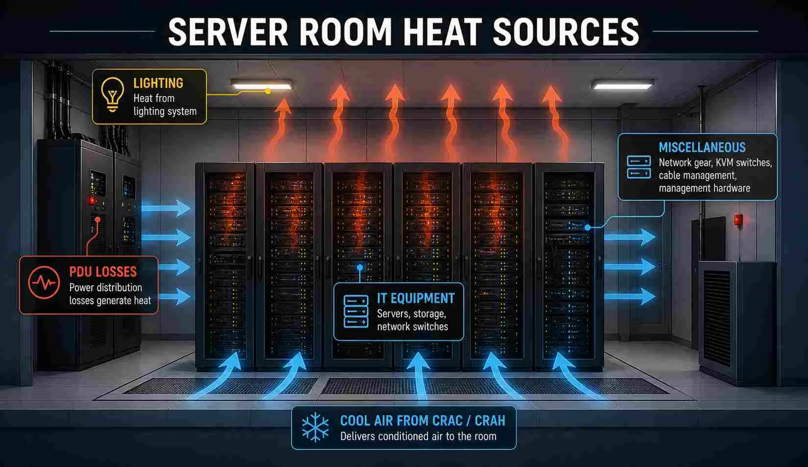
Server room heat comes from four distinct sources: IT equipment, PDU losses, lighting, and miscellaneous infrastructure. IT equipment converts nearly 100% of consumed electrical power to heat — making rack count and average IT load per rack the primary design parameters. PDU losses add 2–8% of IT load depending on unit type and age. Lighting and ancillary gear (KVM switches, management systems, network equipment) typically contribute the remaining 1–3%.
| Parameter | Range | Source |
|---|---|---|
| Average enterprise rack density (2024) | 8–15 kW | Uptime Institute Annual Survey |
| AI / GPU compute racks | 30–80 kW | NVIDIA H100/H200 reference designs |
| Hyperscale rack density | 15–25 kW | Open Compute Project specs |
| PDU loss factor, modern | 2–4% | Eaton, Schneider Electric datasheets |
| PDU loss factor, isolation-transformer type | 5–8% | Legacy units |
| Hot aisle / cold aisle containment savings | 20–40% on cooling energy | ASHRAE 90.4 |
| ASHRAE A1 inlet air range | 15–32 °C (59–89 °F) | TC 9.9 Thermal Guidelines |
| ASHRAE A4 inlet air range | 5–45 °C (41–113 °F) | TC 9.9 Thermal Guidelines |
| Typical enterprise PUE | 1.5–1.8 | Uptime Institute |
Why Server Rack Heat Load Matters
Per-rack density is the threshold that determines which cooling technology is viable. Room-level CRAC units handle densities up to roughly 10 kW per rack with hot aisle/cold aisle containment in place. In-row cooling extends the viable range to 20 kW. Above 20 kW — where AI and GPU compute racks now routinely operate — direct liquid cooling or immersion is the only practical option.
Cooling sizing errors carry higher consequences in data centers than in most HVAC applications. A single CRAC failure with no N+1 redundancy causes thermal shutdown within minutes. Over-provisioned cooling wastes capital and increases facility PUE. Using actual measured IT load rather than nameplate ratings, and applying a realistic PDU loss factor, gives the most accurate input for CRAC selection and central plant sizing.
Practical Tips
- Use measured IT load from a power audit, not nameplate ratings. Nameplate reflects design maximum current; real load is typically 40–70% of nameplate for enterprise servers and 70–90% for AI/HPC deployments.
- Apply N+1 redundancy to CRAC selection. For a 156 kW room load, install two 160 kW units or three 80 kW units — not a single oversized unit with no backup.
- Identify and size high-density racks separately. A room averaging 9 kW/rack that includes two GPU racks at 40 kW needs targeted liquid cooling for those racks regardless of the room average.
- Account for PUE at the plant level. Q_total is IT-side heat only. At PUE 1.5, the chilled water plant and condensing equipment must handle 50% more than Q_total.
HVAC Unit Conversions
| Quantity | Metric | Imperial | Factor |
|---|---|---|---|
| Heat load | W | BTU/hr | 1 W = 3.412 BTU/hr |
| Heat load | kW | BTU/hr | 1 kW = 3,412 BTU/hr |
| Cooling capacity | kW | tons | 1 kW = 0.284 tons |
| Heat density | W/m² | BTU/hr·ft² | 1 W/m² = 0.317 BTU/hr·ft² |
| Temperature | °C | °F | T(°F) = T(°C) × 1.8 + 32 |
Applications
- Enterprise data center CRAC and CRAH unit sizing
- Server room cooling capacity planning
- Edge data center and telecom room heat load estimation
- Colocation facility rack power and cooling planning
- In-row cooling and rear-door heat exchanger sizing
- Hot aisle / cold aisle containment design
- UPS and PDU sizing support
- Data center capacity management and expansion planning
- Small business server closet cooling estimation
- HPC and GPU cluster cooling feasibility review
Example Calculation
Worked example
Mid-sized colocation room, 20 racks at 7.5 kW each.
Inputs:
- N = 20 racks
- Q_rack = 7.5 kW
- L_PDU = 4%
- Q_lighting = 440 W
- Q_misc = 300 W
- A_floor = 65 m² (700 ft²)
Calculations:
- Q_IT = 20 × 7.5 kW = 150.0 kW
- Q_PDU = 150.0 × 0.04 = 6.0 kW
- Q_lighting = 0.44 kW
- Q_misc = 0.30 kW
- Q_total = 156.74 kW = 535,000 BTU/hr = 44.6 tons cooling
- Q_per_rack = 156.74 / 20 = 7.84 kW per rack
- ρ_cooling = 156,740 / 65 = 2,411 W/m² (765 BTU/hr·ft²)
Density tier: MODERATE (7.84 kW per rack falls in the 5–10 kW band).
Cooling design implications:
- IT load dominates at 96% of total — typical for enterprise rooms.
- Standard CRAC at room level is feasible with hot aisle / cold aisle containment.
- For N+1 redundancy at 156.74 kW, install 2× 160 kW CRAC units, or 3× 80 kW units.
- Apply your facility PUE separately for the full plant — at PUE 1.5, the chilled water plant must support ~235 kW.
- 2,411 W/m² is in the standard raised floor airflow range; CFD not required.
Standards & References
- ASHRAE Datacom Series — Thermal Guidelines for Data Processing Environments (TC 9.9) — equipment classes A1–A4, inlet air temperature ranges, allowable operating envelopes.
- ASHRAE Standard 90.4-2022 — Energy Standard for Data Centers. Mechanical and electrical efficiency targets, including economizer requirements by climate zone.
- Uptime Institute Tier Standard: Topology — Tier I through Tier IV redundancy classifications for N+1 and 2N CRAC sizing.
- ANSI/TIA-942-C — Telecommunications Infrastructure Standard for Data Centers. Includes thermal management and rack layout requirements.
- Open Compute Project (OCP) — Open Rack v3 thermal specifications for hyperscale rack density reference.
- Uptime Institute Global Data Center Survey 2024 — published rack density and PUE benchmarks.
Limitations
- This calculator is a sizing reference for room-level air cooling, not a thermal model. It does not predict rack inlet temperatures, hot spots, or containment effectiveness — those require CFD. It does not include UPS battery heat, chilled water plant losses, or condensing capacity sizing. It does not apply PUE; the output is IT-side heat load only. CRAC redundancy (N+1, 2N) is a design choice you apply on top of the result.
Common Mistakes to Avoid
- Sizing CRAC at exactly Q_total without N+1. A 156 kW load served by a single 160 kW CRAC has no redundancy — when that unit fails, the room shuts down within minutes. Industry baseline is N+1, which means installed capacity ≥ 1.5× design load for two units, or ≥ 1.33× for three.
- Using nameplate equipment power instead of measured. Nameplate is design maximum, real load is typically 40–70% of nameplate for enterprise, 70–90% for AI/HPC. Sizing by nameplate over-provisions cooling by 30–50%.
- Ignoring the difference between average and peak rack density. A room with 18 racks at 6 kW and 2 racks at 40 kW has an average density of 9.4 kW — but the high-density racks need their own cooling solution regardless of room average.
- Forgetting PUE when sizing the full plant. Q_total is IT heat. The chilled water plant, condensing units, and pumps must handle Q_total × PUE — typically 30–80% more capacity at the plant level.
- Treating PDU loss as fixed. PDU efficiency varies with load — units run least efficiently at 10–20% load, peak at 40–60% load. Don't assume current PDU loss percentage when sizing for future load.
Frequently Asked Questions
How do you calculate server rack heat load?
How many BTU per hour does a server rack produce?
What is the difference between CRAC and CRAH units?
Does this calculator include PUE?
When is in-row cooling required instead of room-level CRAC?
What is the typical kW per rack in 2024?
Does this calculator include liquid cooling loads?
Frequently Used Together
Engineers often use these calculators in combination for complete project workflows:
Related Calculators
Explore similar calculators that might be useful for your project:
Free HVAC Quick Reference. Formulas & Checks.
Airflow, loads, refrigerant & duct checks — one printable page for the job site.
- Key formulas for airflow, load, refrigerant charge & duct sizing
- Quick sanity checks for the most common HVAC design errors
- Printable one-pager for field use and design review
No spam. Unsubscribe any time.
Calculate
Total number of server racks in the room (integer count)
Average electrical power consumed by IT equipment per rack (BTU/hr)
Percentage of IT load lost as heat in power distribution units (typical 2–8%)
Total lighting heat load for the server room (BTU/hr)
Heat from KVM switches, management equipment, cable infrastructure, and other non-rack sources (BTU/hr)
Net floor area of the server room (optional — used for cooling density calculation)