The One Constraint That Decides Whether Radiant Floor Heating Works at All
A radiant floor is the only heat emitter in a building whose capacity is set by a part of the human body rather than by the equipment feeding it. A panel radiator can sit at 75°C (167°F) in the corner of a room and nobody objects, because nobody stands on it. A floor is walked on, frequently barefoot, and every design question about radiant floors traces back to the temperature a foot will tolerate.
Comfort work puts the practical ceiling for an occupied floor surface near 29°C (84°F), and nearer 27°C (81°F) in rooms where people spend long periods. Those surface temperatures convert directly into a maximum output per unit area, about 100 W/m² (31.7 BTU/hr·ft²) and 76 W/m² (24.0 BTU/hr·ft²) respectively at 20°C (68°F) room air. No increase in water temperature, no larger boiler, and no faster pump moves those figures, because each of those levers raises the surface temperature alongside the output.
The consequence is unusual among heating systems. If a room loses more heat per square metre of heated floor than the floor can emit inside its surface limit, radiant floor heating cannot carry that room on its own. The remedy is a better envelope, a larger heated area, or a second emitter, and hotter water is not on the list.
The calculator estimates output from the mean water temperature, the tube spacing, and the resistance of the floor covering. It states plainly that it does not compute floor surface temperature and does not check comfort limits, and that omission is exactly where engineering judgement has to be applied. This article covers that check and what follows from it: why the floor covering is the most disruptive variable in the whole system, why tighter spacing is usually a better purchase than hotter water, and why the same slab construction behaves so differently outdoors, where the snow melt article dealt with a heated surface carrying no upper limit at all.
Calculator Inputs: Two Water Temperatures, a Spacing, and an R-Value
Five fields and a unit toggle, and one of the five carries more design consequence than the other four together.
Unit System. Imperial (°F, in, h·ft²·°F/BTU, BTU/hr·ft²) or Metric (°C, mm, m²·K/W, W/m²).
Supply Water Temperature [°F or °C]. The design flow temperature into the loops. Radiant floors run at 35 to 50°C (95 to 122°F), well under the 55 to 80°C (131 to 176°F) of radiator systems.
Return Water Temperature [°F or °C]. The design temperature coming back from the loops. The drop across a floor circuit normally sits between 5 and 10 K (9 and 18°F).
Room Air Temperature [°F or °C]. The design indoor temperature, typically 20 to 22°C (68 to 72°F) in living space and 22 to 24°C (72 to 75°F) in bathrooms.
Tube Spacing. Four options, each carrying a fixed factor: 150 mm (6 in) at 1.20, 225 mm (9 in) at 1.00, 300 mm (12 in) at 0.85, and 375 mm (15 in) at 0.72.
Floor Covering Resistance [h·ft²·°F/BTU or m²·K/W]. The thermal resistance of the finish layer above the screed. Tile runs 0.02 to 0.05 m²·K/W (0.11 to 0.28 h·ft²·°F/BTU), engineered board 0.10 to 0.15 (0.57 to 0.85), carpet with underlay 0.15 to 0.26 (0.85 to 1.48).
Outputs are the mean water temperature and the output per unit of heated floor area.
What the model does not return:
Floor surface temperature, the quantity that limits everything else.
Loop length, pressure drop, pump head, flow rate, circuit balancing.
Downward loss into whatever sits below the slab.
Slab thermal inertia and the time taken to reach steady output.
The absence of surface temperature from the output list is the defining feature of this model, and the section on the surface temperature ceiling below shows how to recover that value from the number the page does report.
Why Mean Water Temperature and Not Supply
The driving force is the average of supply and return rather than the supply alone, because the water cools as it travels the loop and the far end of the circuit works against a smaller temperature difference than the near end.
MWT = (T_supply + T_return) / 2
What happens along the circuit:
Water enters hot and gives up heat over the whole run.
By the end of the loop it is cooler, and the floor above that end
emits less than the floor above the entry.
The mean water temperature represents the loop as a single number.
Why supply alone overstates the result:
At 43°C (109.4°F) supply and 38°C (100.4°F) return, the mean is 40.5°C (104.9°F).
Against a 21°C (69.8°F) room, supply alone gives a difference of 22 K (39.6°F)
in place of the true 19.5 K (35.1°F), overstating output by 13%.
The loop temperature drop as a design choice:
A small drop, around 5 K (9°F), gives a more even floor temperature and
demands more flow. A large drop, 10 K (18°F) and above, saves flow but
widens the difference between the start and the end of the loop, which a
spiral layout spreads across the area more evenly than a serpentine one does.
The link to balancing:
The design temperature drop is only achieved at the design flow through
each loop. An unbalanced manifold runs a wide drop in some circuits and a
narrow one in others, and the mean water temperature then stops matching
the design figure everywhere.
Per EN 1264 and ASHRAE Handbook, HVAC Systems and Equipment (2020): floor output is driven by the mean water temperature relative to room air, since the water cools along the circuit and the supply temperature alone overstates the driving force.
The Three-Factor Model and What Each Factor Represents
The model multiplies a temperature difference by two dimensionless factors, one for how densely the tubes are laid and one for what sits on top of the slab, and each factor stands in for a physical mechanism.
Imperial: q = 2.0   × (MWT − T_room) × F_s × F_r    [BTU/hr·ft²]
Metric:   q = 11.36 × (MWT − T_room) × F_s × F_r    [W/m²]

MWT − T_room = mean water above room air, 10 to 25 K (18 to 45°F) typical
F_s          = tube spacing factor, 0.72 to 1.20, dimensionless
F_r          = floor covering factor, 0.25 to 0.90, dimensionless

11.36 = 2.0 × 5.678, where 5.678 W/(m²·K) per BTU/(hr·ft²·°F) already
carries the change of degree scale: 3.15459 × 1.8 = 5.678
The spacing factor:
150 mm (6 in):  1.20        300 mm (12 in): 0.85
225 mm (9 in):  1.00        375 mm (15 in): 0.72
What it represents:
Between the tubes the slab is cooler than directly above them.
The wider the spacing, the cooler those gaps run and the lower the
mean surface temperature is at the same water temperature.
The factor accounts for that unevenness, not for the quantity of
tube per square metre.
The covering resistance factor:
Imperial: F_r = 1 / (1 + R / 0.50)     R in h·ft²·°F/BTU
Metric:   F_r = 1 / (1 + R / 0.088)    R in m²·K/W
What it represents:
The reference value of 0.088 m²·K/W (0.50 h·ft²·°F/BTU) is the resistance
at which the factor equals exactly one half, and it corresponds roughly to
the resistance of the construction above the tubes. A covering matching
the construction resistance halves the output, which is where the form
of the expression comes from.
The shape of that curve matters as much as its value:
The factor falls hyperbolically rather than linearly. The first increments
of resistance cost far more than the later ones: going from 0 to 0.088 m²·K/W
halves the output, while going from 0.088 to 0.176 removes only a further third.
Per the calculator's stated model and EN 1264: output scales with the mean water to room temperature difference, with dimensionless factors representing tube spacing uniformity and the added resistance of the finish floor.
The Surface Temperature Ceiling the Model Does Not See
Output and floor surface temperature are two views of the same quantity. Because comfort standards cap the second, they cap the first, and that is the constraint the model reports around rather than enforces.
The relation between output and surface excess over room air:
Metric:   q ≈ 8.92 × (T_surface − T_room)^1.1    [W/m², difference in K]
Imperial: q ≈ 1.48 × (T_surface − T_room)^1.1    [BTU/hr·ft², difference in °F]

The exponent sits slightly above unity because the radiant component grows
faster than the convective one. Across the narrow range of excesses that
occur in practice the relation is close to linear.
The limits and the output each one permits, at 20°C (68°F) room air:
27°C (81°F), living areas:        excess  7 K (12.6°F) →  76 W/m² (24.0 BTU/hr·ft²)
29°C (84°F), occupied zone:       excess  9 K (16.2°F) → 100 W/m² (31.7 BTU/hr·ft²)
33°C (91°F), bathrooms:           excess 13 K (23.4°F) → 150 W/m² (47.5 BTU/hr·ft²)
35°C (95°F), perimeter strips:    excess 15 K (27.0°F) → 175 W/m² (55.6 BTU/hr·ft²)
What that means for the worked case on the calculator page:
The metric example returns 110.8 W/m² (35.1 BTU/hr·ft²) and flags it HIGH.
That output corresponds to an excess of about 9.9 K (17.8°F), so a surface
near 30.9°C (87.6°F) against the 21°C (69.8°F) room air of the example.
It sits above the living area figure and above the general occupied limit.
The arithmetic is correct and the construction is unacceptable in a living room.
Why no equipment lifts the ceiling:
Hotter water raises the surface temperature along with the output.
Closer spacing does the same.
Neither lever in the model increases output without moving the surface,
so the comfort limit is a limit on the system rather than on its settings.
What to do when the load sits above the ceiling:
Reduce the load: insulation, glazing, air tightness.
Enlarge the heated area if it is smaller than the room.
Add a second emitter: radiator, convector, or skirting heater.
Move part of the load onto a perimeter strip carrying a higher limit.
Raising the water temperature further at this point achieves nothing useful.
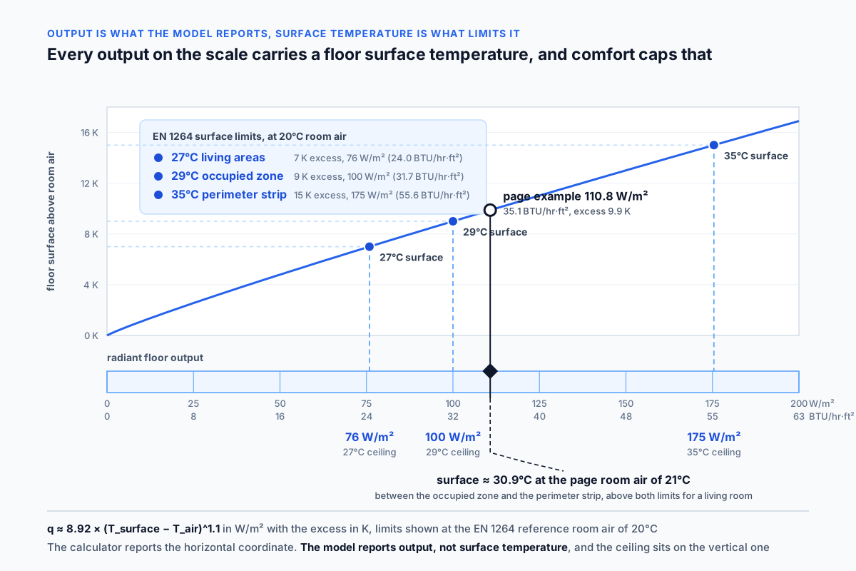
Per EN 1264 and ASHRAE Standard 55-2023: occupied floor surface temperature is limited to roughly 29°C (84°F), and lower in living areas, which places a ceiling near 100 W/m² (31.7 BTU/hr·ft²) on floor output that no increase in water temperature can lift.
Floor Covering Is the Variable the Occupant Controls
Of everything in the model, the floor covering has the widest range, the largest effect, and the unique property that it can be changed after handover by somebody who has never seen the calculation.
Resistance of common coverings:
Tile, stone:              0.02 to 0.05 m²·K/W (0.11 to 0.28 h·ft²·°F/BTU)
Laminate with underlay:   0.08 to 0.12        (0.45 to 0.68)
Engineered board:         0.10 to 0.15        (0.57 to 0.85)
Solid timber board:       0.13 to 0.18        (0.74 to 1.02)
Carpet with underlay:     0.15 to 0.26        (0.85 to 1.48)
What that does to the factor:
Tile, R 0.03:             F_r = 1 / (1 + 0.03/0.088)  = 0.75
Laminate, R 0.088:        F_r = 1 / (1 + 0.088/0.088) = 0.50
Engineered board, R 0.12: F_r = 1 / (1 + 0.12/0.088)  = 0.42
Carpet, R 0.20:           F_r = 1 / (1 + 0.20/0.088)  = 0.31
Output at one and the same water temperature, at 19.5 K (35.1°F) above room air and 225 mm (9 in) spacing:
Tile:              11.36 × 19.5 × 1.00 × 0.746 = 165 W/m² (52.4 BTU/hr·ft²)
Laminate:          11.36 × 19.5 × 1.00 × 0.500 = 111 W/m² (35.1 BTU/hr·ft²)
Engineered board:  11.36 × 19.5 × 1.00 × 0.423 =  94 W/m² (29.7 BTU/hr·ft²)
Carpet:            11.36 × 19.5 × 1.00 × 0.306 =  68 W/m² (21.5 BTU/hr·ft²)
A spread of 2.4 with the system completely unchanged, and the reason this variable breaks more radiant installations than any other:
A floor is designed for tile, commissioned, and handed over. A year later
the occupant lays carpet. Output falls by more than half, the room
underheats, and nothing has failed: the system performs exactly as the
new covering allows.
What is done about it at design stage:
Size against the worst covering the space is likely to receive rather than
the one on the finishes schedule.
State a maximum covering resistance in the design documents and hand that
limit to the client in writing.
Leave headroom in water temperature where the surface limit still allows it.
Treating the resistance as a design requirement rather than a preference:
EN 1264 works with a limiting covering resistance for a given output, and
exceeding that value moves the system into a different operating regime
rather than reducing the result slightly.
Per EN 1264 and manufacturer data: floor covering resistance ranges from about 0.02 m²·K/W (0.11 h·ft²·°F/BTU) for tile to 0.26 (1.48) for carpet with underlay, a spread that changes the output factor by more than a factor of two and can be altered by the occupant after handover.
Tube Spacing Buys Output Without Raising Water Temperature
Between the two levers available to the designer, tighter spacing and hotter water, spacing is usually the better purchase, because it raises output while leaving the water temperature low.
What each step in the spacing sequence returns:
375 → 300 mm (15 → 12 in): factor 0.72 to 0.85, output up 18%
300 → 225 mm (12 →  9 in): factor 0.85 to 1.00, output up 18%
225 → 150 mm ( 9 →  6 in): factor 1.00 to 1.20, output up 20%
The full range, 375 to 150 mm, is a factor of 1.67
What buying the same increase through temperature costs:
Matching that 1.67 at 225 mm (9 in) spacing means lifting the difference
above room air from 19.5 to 32.5 K (35.1 to 58.5°F), which takes the mean
water from 40.5 to 53.5°C (104.9 to 128.3°F).
The surface temperature rises with it, and the comfort limit arrives first.
Why low water temperature is worth something on its own:
A condensing boiler runs more efficiently the cooler its return.
A heat pump loses coefficient of performance with every degree of supply
temperature. A radiant floor at 35 to 45°C (95 to 113°F) supply is the
emitter that makes a low temperature source worth installing.
What close spacing costs:
More tube per square metre, more installation time, higher pressure drop
per loop and, at a fixed maximum loop length, less area served by each loop.
The extra pipe is usually cheap next to what the lower water temperature is
worth over the life of the system.
Surface evenness:
Close spacing narrows the temperature difference between the strip above a
tube and the gap between tubes, which is noticeable underfoot on tile and
nearly imperceptible under carpet. At 300 mm (12 in) and wider that
unevenness becomes detectable by a bare foot.
Per EN 1264 and Radiant Professionals Alliance design guidance: closer tube spacing raises output by roughly a fifth per step in the standard sequence while keeping water temperature low, which suits condensing boilers and heat pumps better than raising the supply temperature does.
Perimeter Zones and Bathrooms Sit Under Different Limits
The comfort ceiling is not a single number for the whole building, and the zones where it relaxes are precisely the zones where the heat is needed most.
The differentiated limits:
Living areas of long occupancy:        about 27°C (81°F)
General occupied zone:                 about 29°C (84°F)
Bathrooms and wet rooms:               up to 33°C (91°F)
Perimeter strips along glazing:        up to 35°C (95°F)
Why the perimeter limit is higher:
The strip along external glazing, roughly a metre (3 ft) wide, is occupied
rarely and briefly. It is also where heat loss concentrates and where the
cold radiant field from the glass is felt most strongly. Raising output in
that strip answers both at once.
How that is used:
Tube spacing in the perimeter strip is laid closer than in the field,
reaching up to 175 W/m² (55.6 BTU/hr·ft²) against roughly 100 W/m²
(31.7 BTU/hr·ft²) in the main zone. That covers the room load while the
occupied area stays inside its own limit.
Bathrooms:
The higher limit there reflects brief barefoot occupancy, where a warm floor
reads as a comfort feature rather than a source of discomfort. The binding
constraint becomes the covering material and its adhesive rather than the
sensation underfoot.
What the model does not distinguish:
The calculator returns one number for the conditions entered and has no
knowledge of which zone is being designed. Splitting a floor into zones with
different limits and different spacings is the designer's work.
Per EN 1264 and ISO 11855: surface temperature limits differ by zone, with roughly 29°C (84°F) in occupied areas, up to 33°C (91°F) in bathrooms, and up to 35°C (95°F) in perimeter strips along glazing where occupancy is brief and heat loss is concentrated.
Downward Loss Is Not in the Model and Not Always Small
The model reports what goes up, while the slab also sends heat down, and the share travelling the wrong way depends entirely on what sits under the tubes.
Where the downward heat goes:
Ground slab with insulation beneath: downward loss is small and partly
  recovered, since the soil under the slab warms up.
Floor over a heated space below: downward loss heats the storey underneath,
  so it is not lost, but it is not counted in the result either.
Floor over a basement, passage, or outside air: downward loss is a straight
  loss, and without adequate insulation it is substantial.
Order of magnitude:
With a well insulated build-up beneath the tubes, downward loss runs at a
few percent of the output. With thin or omitted insulation over an unheated
space, it rises towards a quarter, which means a quarter of the installed
capacity heating a passage rather than a room. The split follows the ratio
of the resistances above and below the tubes.
What the standards require:
EN 1264 sets a minimum insulation resistance beneath the system according to
what lies below it, and the requirement is strictest where the floor sits
over outside air.
How that enters source selection:
Upward output is what covers the room load.
The source has to cover upward output plus downward loss.
The calculator gives the first and not the second.
Per EN 1264: minimum insulation resistance beneath the system depends on what lies below, and downward loss ranges from a few percent over a well insulated ground slab to roughly a quarter over an unheated space with inadequate insulation.
Low Water Temperature Is Why Radiant Suits Heat Pumps
A radiant floor asks for the coolest water of any emitter in the building, and that single property is what makes heat pumps and condensing boilers work near their best rather than near their worst.
Water temperature by emitter type:
Cast iron radiators, older systems:  70 to 90°C (158 to 194°F) supply
Modern panel radiators:              55 to 70°C (131 to 158°F)
Fan coil units:                      45 to 55°C (113 to 131°F)
Radiant floor:                       35 to 45°C ( 95 to 113°F)
What that gives a heat pump:
Coefficient of performance falls roughly 2 to 3% for every degree of supply
temperature. The gap between 55 and 40°C (131 and 104°F) is 15 K (27°F),
which is on the order of a third of the electrical input for the same
delivered heat.
What it gives a condensing boiler:
Condensation begins once the return falls below the dew point of the flue
gas, near 55°C (131°F) for natural gas. A floor circuit returning at 35°C
(95°F) holds the boiler in condensing operation continuously, while a
radiator system drops out of it exactly when outdoor temperatures are
lowest and the saving matters most.
The other side of it:
Low temperature means a small driving force into the room, and therefore a
large emitting surface. That is why the system is expected to occupy the
whole floor rather than part of it, and why it is so sensitive to the
covering: at a difference of 20 K (36°F) an extra resistance on top costs
proportionally more than it would at 50 K (90°F).
Inertia as a consequence:
A slab with tubes in it stores heat and keeps releasing it for hours after
the source stops. That smooths the operation of the source and rules out
quick response to a change in load, which makes weather compensated control
a better fit than room thermostat control on deviation alone.
Per ASHRAE Handbook, HVAC Systems and Equipment (2020) and heat pump application literature: radiant floors operate at 35 to 45°C (95 to 113°F) supply against 55 to 70°C (131 to 158°F) for panel radiators, and since heat pump performance falls roughly 2 to 3% per degree of supply temperature, the emitter choice governs the efficiency of the source.
Comparing Output Against Load per Heated Area, Not per Room
The output the calculator returns is per square metre of heated floor. Comparing it against a room load means dividing that load by the area actually covered by tubing, which is normally smaller than the room.
What the tubing does not run under:
Fitted furniture, kitchen units, islands.
Baths, shower trays, sanitary ducts.
Setbacks from external walls and from fixed furniture in the layout.
Areas at door openings and under partitions.
Order of magnitude:
In a living room the heated area usually comes to 85 to 95% of the room area.
In a kitchen with fitted units, or a bathroom, it can fall to 60 to 70%.
What the error does:
A 20 m² (215 ft²) room with a 1,400 W (4,780 BTU/hr) load gives 70 W/m²
(22.2 BTU/hr·ft²) when divided by the full room area.
With 14 m² (151 ft²) actually heated, the same load requires 100 W/m²
(31.7 BTU/hr·ft²), which lands exactly on the occupied zone limit.
The same design reads as comfortable or as impossible depending on which
area the load was divided by.
How to do it correctly:
Required output = room load / heated floor area.
Compare that against the calculator result.
Both quantities have to refer to the same area.
The kitchen as the characteristic case:
A kitchen combines the smallest heated fraction with an external wall and
an extract fan, meaning a high load over a small area. It is the room that
most often needs a supplementary emitter.
Per EN 1264 and Radiant Professionals Alliance guidance: floor output is stated per unit of heated floor area, so room load must be divided by the area actually covered by tubing, which commonly runs 85 to 95% of a living room and considerably less in kitchens and bathrooms.
Worked Example: 105 Degrees Mean Water to 35 BTU per Hour per Square Foot
The scenario matches the Imperial example on the calculator page.
Supply 110°F (43.3°C), return 100°F (37.8°C)
Room air 70°F (21.1°C)
Spacing 9 in (225 mm)
Covering resistance 0.50 h·ft²·°F/BTU (0.088 m²·K/W)
Step 1. Mean water temperature.
MWT = (110 + 100) / 2 = 105°F (40.6°C)
Step 2. Spacing factor.
9 in (225 mm) → F_s = 1.00
Step 3. Covering factor.
F_r = 1 / (1 + 0.50/0.50) = 0.50
The covering resistance equals the reference value, so the output is
halved exactly.
Step 4. Output.
q = 2.0 × (105 − 70) × 1.00 × 0.50 = 35.0 BTU/hr·ft² (110.4 W/m²)
Step 5. How the page reads it.
35.0 BTU/hr·ft² is flagged HIGH.
Step 6. The surface temperature check.
110.4 W/m² corresponds to an excess of about 9.9 K (17.7°F) over room air,
so a floor surface near 31.0°C (87.7°F) against 21.1°C (70°F) air.
That is above the occupied zone limit of about 29°C (84°F) and well above
the 27°C (81°F) figure for living areas.
Step 7. What the discrepancy means.
The arithmetic is right and the model does exactly what it claims.
A floor like this is still not acceptable in a living room, so the result
should be read as an instruction to revisit the inputs rather than as
confirmation of the design.
Step 8. Which covering the entered resistance describes.
0.088 m²·K/W (0.50 h·ft²·°F/BTU) corresponds roughly to a thin laminate
over underlay. Under tile at the same water temperature the output would be
2.0 × 35 × 1.00 × 0.75 = 52 BTU/hr·ft² (165 W/m²), which puts the surface
near 35°C (95°F) and is admissible only in a perimeter strip.
Step 9. Bringing it inside the living area limit.
To reach 24.0 BTU/hr·ft² (76 W/m²) at the same covering and spacing, the
difference above room air has to be about 24°F (13.4 K) in place of 35°F,
so a mean water temperature near 94°F (34.5°C).
At the same 10°F (5.6 K) loop drop that is a supply of about 99°F (37.3°C).
Step 10. Result.
35.0 BTU/hr·ft² (110.4 W/m²) at 105°F (40.6°C) mean water.
The figure exceeds the surface temperature limit for living areas.
It suits a perimeter strip or a bathroom, and for a living room it needs
the supply dropped to roughly 99°F (37°C).
Metric Worked Example and the Covering Comparison
The scenario matches the Metric example on the calculator page.
Supply 43°C (109.4°F), return 38°C (100.4°F), room 21°C (69.8°F)
Spacing 225 mm (9 in), covering resistance 0.088 m²·K/W (0.50 h·ft²·°F/BTU)

MWT = 40.5°C (104.9°F)
F_s = 1.00
F_r = 1 / (1 + 0.088/0.088) = 0.50
q   = 11.36 × (40.5 − 21) × 1.00 × 0.50 = 110.8 W/m² (35.1 BTU/hr·ft²)
Reconciling the two examples:
The Imperial case gives 35.0 BTU/hr·ft², which converts to 110.4 W/m².
The Metric case gives 110.8 W/m².
The 0.3% gap comes from rounded inputs: 43/38/21°C is not the exact
equivalent of 110/100/70°F, and 0.088 m²·K/W is rounded from 0.0881.
The model is consistent; only the starting values differ.
Coverings compared with everything else held still, at 19.5 K (35.1°F) above room air and 225 mm (9 in) spacing:
Tile, R 0.03 m²·K/W (0.17):            F_r 0.75 → 165 W/m² (52.4 BTU/hr·ft²)
Laminate, R 0.088 (0.50):              F_r 0.50 → 111 W/m² (35.1 BTU/hr·ft²)
Engineered board, R 0.12 (0.68):       F_r 0.42 →  94 W/m² (29.7 BTU/hr·ft²)
Carpet with underlay, R 0.20 (1.14):   F_r 0.31 →  68 W/m² (21.5 BTU/hr·ft²)
The surface temperatures those outputs imply, against 21°C (69.8°F) room air:
Tile:              35.2°C (95.4°F), perimeter strip territory
Laminate:          30.9°C (87.6°F), above the occupied zone limit
Engineered board:  29.5°C (85.1°F), marginally above it
Carpet:            27.3°C (81.2°F), inside the occupied limit and only
                   just above the living area figure
What follows for the design:
Tile to carpet is a factor of 2.4 with the system entirely unchanged.
Only the carpeted case clears the occupied zone limit at this water
temperature; the other three call for cooler water in a living room.
One construction behaves as four different systems depending on the
layer laid on top of it.
The inverse problem:
Where the room load over the heated area comes to 70 W/m² (22.2 BTU/hr·ft²),
the carpeted floor barely covers it, the boarded floor has a third in hand,
and the tiled floor needs the water dropped to keep the surface within
limits.
Per EN 1264: at an unchanged mean water temperature and tube spacing, floor covering resistance alone changes output by a factor of about 2.4 between tile and carpet with underlay.
Application Boundaries: Surface Temperature, Loop Design, Transients
The model is a preliminary estimate of output per unit heated area from the mean water temperature, the tube spacing, and the covering resistance. The following need separate treatment.
Floor surface temperature. The model neither computes it nor checks it against comfort limits, even though that limit governs the entire system. The check has to be made separately, as set out above.
Downward loss. Upward output covers the room load. The source has to cover downward loss as well, which depends on the insulation under the tubes and on what lies beneath.
Loop design. Loop length, pressure drop, pump head, flow rate, the number of circuits, manifold balancing, and layout pattern all sit outside the model.
Thermal inertia. The slab takes hours to reach steady output and keeps emitting after shutdown. Dynamics, response to load change, and the choice of control strategy are not addressed.
Floor construction. The model does not distinguish a concrete slab from a dry board system or tubing between joists, which deliver materially different output at the same water temperature and spacing.
The reference resistance. The value of 0.088 m²·K/W (0.50 h·ft²·°F/BTU) is fixed and reflects a typical build-up above the tubes. A different screed thickness or a different material shifts it.
Manufacturer data. Final selection follows the tested performance of the specific system rather than a generalised model.
Heated area. The result is per square metre of heated floor, and comparison against a load requires dividing by that area rather than by the room area.
Floor cooling. The reverse mode is bounded by surface condensation at the dew point and is outside the scope here.
Per EN 1264, ISO 11855, and ASHRAE Handbook, HVAC Systems and Equipment (2020): the output model is a preliminary screen, while surface temperature verification, downward loss, loop hydraulics, transient behaviour, and manufacturer performance data require separate treatment.
Radiant Floor Heating Output Calculator
Radiant floor output from a three-factor model: takes the mean of the supply and return water temperatures, subtracts the room air temperature, and scales the result by a tube spacing factor and a floor covering resistance factor to give output per unit of heated floor area. Because comfort standards cap the floor surface temperature near 29°C (84°F) in occupied spaces, any output above roughly 100 W/m² (31.7 BTU/hr·ft²) needs checking against that limit rather than against the boiler. A preliminary screen per EN 1264, not a loop design.
Open Radiant Floor Heating Output CalculatorStandards and References
- EN 1264 (Parts 1 to 5), Water Based Surface Embedded Heating and Cooling Systems. Surface temperature limits by zone, calculation of specific output, limiting covering resistance, minimum insulation beneath the system, and test methods.
- ISO 11855 (Parts 1 to 6, 2021), Building Environment Design, Embedded Radiant Heating and Cooling Systems. Design, output calculation, and control of embedded radiant systems.
- ASHRAE Handbook, HVAC Systems and Equipment (2020), Chapter 6, Panel Heating and Cooling. The relation between panel output and surface temperature, the split between radiant and convective components, and reference output data.
- ASHRAE Handbook, Fundamentals (2025), Chapter 4, Heat Transfer. Radiant and convective exchange between a surface and the space it faces.
- ASHRAE Standard 55-2023, Thermal Environmental Conditions for Human Occupancy. Local discomfort from warm floors and acceptable surface temperature in the occupied zone.
- Radiant Professionals Alliance, Radiant Panel Association Design Guidelines (2018 onward). Practical guidance on tube spacing, zoning, and loop layout.
- Manufacturer performance data for radiant floor systems (2020 onward). Specific output by construction type, spacing, and covering, with maximum permitted fluid temperatures.
- Heat pump application literature on low temperature emitters (2019 onward). Dependence of coefficient of performance on supply temperature and emitter selection for low temperature sources.
FAQ
How is radiant floor output calculated?
Per EN 1264 and the calculator's model: take the mean of the supply and return water temperatures, subtract the room air temperature, and scale the difference by a tube spacing factor and a floor covering resistance factor. At a mean water temperature of 40.5°C (104.9°F), room air at 21°C (69.8°F), 225 mm (9 in) spacing, and a covering resistance of 0.088 m²·K/W (0.50 h·ft²·°F/BTU), that gives 110.8 W/m² (35.1 BTU/hr·ft²).
What limits how much heat a radiant floor can deliver?
Per EN 1264 and ASHRAE Standard 55-2023: the floor surface temperature, capped near 29°C (84°F) in occupied spaces and closer to 27°C (81°F) in living areas. At 20°C (68°F) room air those surfaces correspond to about 100 W/m² (31.7 BTU/hr·ft²) and 76 W/m² (24.0 BTU/hr·ft²), and no increase in water temperature, boiler size, or pump capacity lifts that ceiling.
Why use mean water temperature rather than supply temperature?
Per EN 1264: because the water cools as it travels the loop, so the far end works against a smaller driving force than the near end. With 43°C (109.4°F) supply and 38°C (100.4°F) return into a 21°C (69.8°F) room, supply alone would give a difference of 22 K (39.6°F) against the true mean of 19.5 K (35.1°F), overstating output by 13%.
How much does floor covering affect output?
Per EN 1264 and manufacturer data: by more than a factor of two. At unchanged water temperature and spacing, tile at 0.03 m²·K/W (0.17 h·ft²·°F/BTU) gives about 165 W/m² (52.4 BTU/hr·ft²) while carpet with underlay at 0.20 m²·K/W (1.14 h·ft²·°F/BTU) gives about 68 W/m² (21.5 BTU/hr·ft²), a ratio of 2.4. It is also the one variable an occupant can change after handover.
Is tighter tube spacing or hotter water the better way to raise output?
Per EN 1264 and Radiant Professionals Alliance design guidance: tighter spacing, in most cases. Going from 375 mm (15 in) to 150 mm (6 in) raises output by a factor of 1.67 with the water temperature untouched, whereas buying the same increase through temperature means lifting mean water from 40.5 to 53.5°C (104.9 to 128.3°F), which pushes the surface past its limit and costs heat pump performance.
Can a radiant floor always carry the room load?
Per EN 1264: no. If the room load per heated square metre exceeds what the floor can emit inside its surface temperature limit, the answer is a better envelope, a larger heated area, or a supplementary emitter. Once the surface limit is reached, hotter water raises the surface temperature rather than solving the shortfall.
Why do radiant floors suit heat pumps?
Per ASHRAE Handbook, HVAC Systems and Equipment (2020): because they ask for 35 to 45°C (95 to 113°F) supply against 55 to 70°C (131 to 158°F) for panel radiators, and heat pump performance falls roughly 2 to 3% per degree of supply temperature. The emitter choice therefore governs how well the source performs.
Related Calculators
- Hydronic Balancing Calculator: Distribution of flow between loops, which decides whether the design temperature drop is achieved and whether the mean water temperature matches the design figure (article).
- HVAC Heat Load Calculator: The room load that floor output has to cover once it is divided by the heated area rather than the room area.
- Heat Exchanger Calculator: Separation of the source primary circuit from the low temperature floor circuit (article).
- Boiler Efficiency Calculator: Boiler efficiency on the low return temperature a floor circuit produces.
- Ground Source Heat Pump COP Estimator: The coefficient of performance that improves as supply temperature falls.
- Glycol Concentration Calculator: Antifreeze for circuits passing through unheated zones (article).
- District Heating Pipe Loss Calculator: Losses in the distribution mains upstream of the building (article).
- Pool Heating Load: The adjacent low temperature case, with a large surface transferring heat at a small driving force.