Why a Heat Exchanger's Driving Force Is a Logarithmic Average, Not a Simple One
A heat exchanger transfers heat in proportion to the temperature difference between its two streams, but that difference is not constant along the exchanger: it is large where the streams first meet and small where they part, so the effective driving force is a logarithmic average of the two ends, the log mean temperature difference, not the simple arithmetic average.
The physics makes this necessary. As the hot stream gives up heat and the cold stream absorbs it, their temperatures converge along the exchanger's length. The temperature difference driving the transfer is therefore different at each cross-section: wide at one end and narrow at the other. Because the local heat transfer rate depends on the local temperature difference, and that difference decays along the length, the correct average is the logarithmic mean, which weights the profile exactly as the exponential decay demands. Using the plain arithmetic average of the two terminal differences overstates the driving force whenever the two ends are unequal, and the error grows as they diverge.
The calculator takes the four terminal temperatures, the flow arrangement, the overall heat transfer coefficient, and the area, computes the two end temperature differences, forms the log mean, and returns the duty as Q = U times A times LMTD, along with an effectiveness indicator. It closes the hydronic sub-cluster at the consumer end: the Glycol article set the loop fluid, Balancing distributed the flow, and District Heating carried the heat to the substation, where a heat exchanger transfers it into the building. The same method sizes any fluid-to-fluid HVAC exchanger: hydronic coils, plate exchangers, and glycol run-around loops. Counterflow and parallel arrangements give different results from the same temperatures, and the overall coefficient carries the fouling that erodes performance over time.
Calculator Inputs: Four Temperatures, Flow Arrangement, U, and Area
The calculator collects eight inputs and returns the duty, LMTD, terminal differences, and an effectiveness indicator.
Unit System. Imperial (°F, BTU/hr·ft²·°F, ft², BTU/hr) or Metric (°C, W/m²·K, m², W). The choice sets every labeled unit; the formula path is fixed in both modes.
Hot Fluid Inlet Temperature [°F or °C]. The hot stream entering. For a district heating substation plate exchanger, this is the primary supply temperature.
Hot Fluid Outlet Temperature [°F or °C]. The hot stream leaving, cooled by the transfer. Must be below the inlet.
Cold Fluid Inlet Temperature [°F or °C]. The cold stream entering. For the secondary building loop, this is the return temperature.
Cold Fluid Outlet Temperature [°F or °C]. The cold stream leaving, warmed. Must be above the cold inlet; in counterflow it may approach or exceed the hot outlet.
Flow Arrangement. Counterflow (streams in opposite directions) or Parallel Flow (same direction). This choice sets how the terminal differences are paired, which is the subject of Section 4.
Overall Heat Transfer Coefficient U [BTU/hr·ft²·°F or W/m²·K]. The combined conductance of both film coefficients and the wall, discussed in Section 8. Use the fouled operating value, not the clean manufacturer figure.
Heat Transfer Area A [ft² or m²]. The surface available for transfer, from exchanger drawings or manufacturer data.
The calculator outputs: Heat Transfer Rate Q (BTU/hr or W), LMTD (°F or °C), Terminal Differences ΔT₁ and ΔT₂ (°F or °C), and Effectiveness ε (%, a supplementary indicator, Section 10).
The page follows one path throughout: temperatures to terminal differences to LMTD to Q = U·A·LMTD. It does not switch into ε-NTU mode; effectiveness is a derived indicator. Inputs that produce zero or negative terminal differences trigger a CHECK INPUTS warning, because they are physically inconsistent for the selected arrangement.
The calculator does not account for pressure drop, fouling evolution over time, phase change, the F correction factor for multi-pass shell-and-tube, variable fluid properties, full ε-NTU behavior, or flow rates and specific heats directly. It is a screening duty estimate.
Terminal Temperature Differences: Where Counterflow and Parallel Diverge
The two terminal temperature differences are the raw material of the LMTD, and the single most important input distinction is the flow arrangement, because counterflow and parallel flow pair the stream temperatures differently.
In counterflow, the streams travel in opposite directions, so the hot inlet end faces the cold outlet, and the hot outlet end faces the cold inlet:
ΔT₁ = T_h,in − T_c,out   (hot inlet meets cold outlet)
ΔT₂ = T_h,out − T_c,in   (hot outlet meets cold inlet)
In parallel flow, both streams enter from the same end and travel in the same direction, so both inlets are together and both outlets are together:
ΔT₁ = T_h,in − T_c,in    (both inlets at the same end)
ΔT₂ = T_h,out − T_c,out  (both outlets at the same end)
The physical picture shows why the pairing matters. In parallel flow, the two inlets meet at one end, creating a large temperature difference there, while both streams converge toward the other end, leaving only a small difference at the outlet. In counterflow, each end pairs an inlet with an outlet, keeping the profile more even along the length.
For the worked case (Sections 12 and 13), T_h,in 180°F, T_h,out 140°F, T_c,in 90°F, T_c,out 120°F:
Counterflow:
ΔT₁ = 180 − 120 = 60°F
ΔT₂ = 140 − 90  = 50°F  (close, even profile)

Parallel:
ΔT₁ = 180 − 90  = 90°F
ΔT₂ = 140 − 120 = 20°F  (wide spread, collapses at outlet)
These pairs feed the LMTD formula, and the more even counterflow pair gives a higher LMTD (Section 7). The physical limits also differ: in counterflow, the cold outlet (120°F) can approach or exceed the hot outlet (140°F) and still be below the hot inlet (180°F), so temperature crosses are possible. In parallel flow, the cold outlet can never exceed the hot outlet, because both streams converge to a common limit.
Per standard LMTD references (ASHRAE Fundamentals, Incropera): counterflow pairs hot inlet with cold outlet for ΔT₁ and hot outlet with cold inlet for ΔT₂; parallel pairs both inlets for ΔT₁ and both outlets for ΔT₂. The same four temperatures yield different terminal differences and thus a different LMTD by arrangement alone.
The Log Mean Temperature Difference and Why It Is Not the Arithmetic Mean
The log mean temperature difference is the exact average driving force for an exchanger, and it is always less than or equal to the arithmetic mean of the two ends, with the gap widening as the ends diverge.
LMTD = (ΔT₁ − ΔT₂) / ln(ΔT₁ / ΔT₂)

Special case: when ΔT₁ = ΔT₂, LMTD = ΔT₁
(the ratio is 1, ln(1) = 0, but the limit as ΔT₁ → ΔT₂ equals ΔT₁)
The logarithm appears because the temperature difference decays exponentially along the exchanger. Integrating the local heat transfer rate over that exponential profile, and then dividing the total by the exchanger length, yields the log mean. It is not an approximation; it is the mathematically correct result of the integration.
The log mean is always less than or equal to the arithmetic mean:
Arithmetic mean = (ΔT₁ + ΔT₂) / 2
LMTD ≤ arithmetic mean, equal only when ΔT₁ = ΔT₂
For the counterflow case (ΔT₁ = 60°F, ΔT₂ = 50°F):
LMTD = (60 − 50) / ln(60/50) = 10 / ln(1.2) = 10 / 0.18232 = 54.85°F
Arithmetic mean = (60 + 50) / 2 = 55°F
Difference: 0.3%  (ends are close, means nearly agree)
For the parallel case (ΔT₁ = 90°F, ΔT₂ = 20°F), the ends diverge widely:
LMTD = (90 − 20) / ln(90/20) = 70 / ln(4.5) = 70 / 1.5041 = 46.54°F
Arithmetic mean = (90 + 20) / 2 = 55°F
Difference: 18%  (arithmetic mean overstates by 18%)
When the terminal differences are similar, as in counterflow with an even profile, LMTD and arithmetic mean are nearly the same. When they diverge, as in parallel flow or any arrangement with a large temperature change on one side, the arithmetic mean overstates the driving force badly. Always use the log mean.
The zero-difference trap: if either ΔT₁ or ΔT₂ is zero or negative, ln(ΔT₁/ΔT₂) is undefined or the logarithm of a negative number. The calculator flags CHECK INPUTS; the temperatures are physically inconsistent for the chosen arrangement.
Per ASHRAE Fundamentals and Incropera: LMTD = (ΔT₁ − ΔT₂)/ln(ΔT₁/ΔT₂), the exact average for the exponential temperature profile. It is always ≤ the arithmetic mean, equal when the ends match, and increasingly lower as they spread. Use the log mean.
The Duty Equation: Q Equals U Times A Times LMTD
The exchanger duty (the heat it transfers) is the product of three factors: how well it conducts heat per unit area (U), how much area it has (A), and how hard the temperature difference drives the transfer (LMTD).
Q = U × A × LMTD

Q    = heat transfer rate [W or BTU/hr]
U    = overall heat transfer coefficient [W/m²·K or BTU/hr·ft²·°F]
A    = heat transfer area [m² or ft²]
LMTD = log mean temperature difference [°C/K or °F]
The equation can be read in two directions. Rating mode: given U, A, and the four terminal temperatures, find the duty Q. This is the calculator's path. Sizing mode: given a required Q and the temperatures, find the area needed, A = Q/(U·LMTD). The calculator returns Q; rearranging gives A.
For the counterflow worked case (U = 35 BTU/hr·ft²·°F = 199 W/m²·K, A = 120 ft² = 11.15 m², LMTD = 54.85°F = 30.5°C):
Q = 35 × 120 × 54.85 = 230,370 BTU/hr (67.5 kW)
Unit consistency is a common error source. U, A, and LMTD must be in one consistent system: U in BTU/hr·ft²·°F with A in ft² and LMTD in °F gives Q in BTU/hr; U in W/m²·K with A in m² and LMTD in °C gives Q in W. Mixing U in W/m²·K with A in ft² produces a dimensionally incorrect result (Application Boundaries, Section 14).
The three factors multiply, so the duty is limited by whichever is smallest. A large area with a fouled U still under-performs. A high U with insufficient area cannot deliver the required duty. All three must be sized together: double the area doubles the duty at the same U and LMTD; improve U by removing fouling and the duty rises proportionally; increase LMTD by widening the temperature difference or switching to counterflow and the duty rises with it.
Per ASHRAE Fundamentals and Kern: duty Q = U·A·LMTD. Rearrange to A = Q/(U·LMTD) for sizing. The three factors multiply; keep units consistent within one system.
Counterflow versus Parallel Flow: The Same Streams, a Larger Driving Force
For the same four terminal temperatures, counterflow always produces an equal or higher LMTD than parallel flow. That is why counterflow is the preferred arrangement: it extracts more duty from the same streams and the same area.
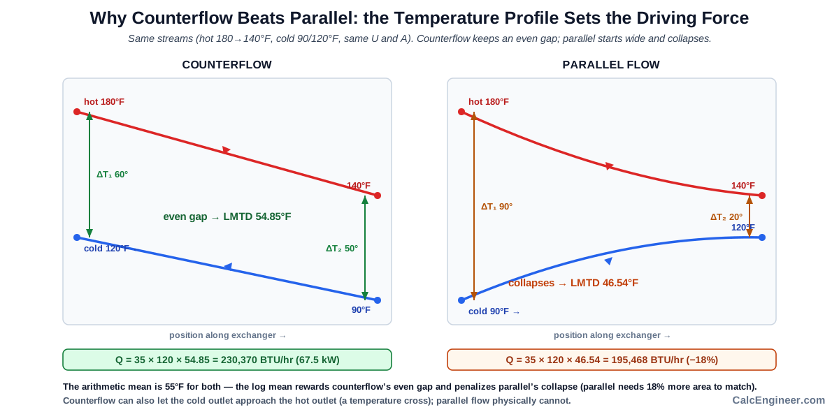
The comparison for the worked case:
Counterflow: ΔT₁ = 60, ΔT₂ = 50°F → LMTD = 54.85°F → Q = 230,370 BTU/hr
Parallel:    ΔT₁ = 90, ΔT₂ = 20°F → LMTD = 46.54°F → Q = 195,468 BTU/hr
Counterflow LMTD is 18% higher for identical streams and area
Counterflow wins because it keeps the temperature difference more even along the exchanger. An even profile has a higher log mean than one that starts large and collapses. The entire surface works against a meaningful driving force. In parallel flow, half the surface faces a large difference and the other half faces a small one, so the average is pulled down by the small end.
The temperature-approach advantage follows from the same geometry. In counterflow, the cold outlet can approach or even exceed the hot outlet, which is impossible in parallel flow. District heating substations and process heat recovery exploit this: counterflow allows a closer approach temperature, recovering more heat from the same streams.
Counterflow can produce a temperature cross (cold outlet above hot outlet). Parallel flow physically cannot. A single-pass parallel exchanger always leaves the cold outlet below the hot outlet, because both streams converge toward the same equilibrium.
Duty consequence at identical U and A:
Counterflow: Q = 230,370 BTU/hr (67.5 kW)
Parallel:    Q = 195,468 BTU/hr (57.3 kW)
To match counterflow duty with parallel, A = 230,370/(35 × 46.54) = 141 ft²
Parallel needs 18% more area for the same duty as counterflow
Parallel flow is used in specific non-thermal situations: limiting wall temperature on the hot side, avoiding freezing at the cold inlet, or for mechanical and manufacturing reasons. For thermal duty, counterflow is the design default.
Per ASHRAE Fundamentals and Incropera: counterflow always gives an equal or higher LMTD than parallel for the same terminal temperatures (54.85 vs 46.54°F in the example, 18% higher), delivering more duty per unit area and allowing a closer temperature approach. Counterflow is the thermal default.
The Overall Heat Transfer Coefficient: Two Films and a Wall in Series
The overall heat transfer coefficient U is not a single material property but the combined result of three resistances in series: the convection film on the hot side, the conduction through the wall, and the convection film on the cold side.
1/U = 1/h_hot + (wall thickness / wall conductivity) + 1/h_cold

h_hot, h_cold = convection film coefficients [W/m²·K or BTU/hr·ft²·°F]
Thermal resistances in series add. Each resistance is the reciprocal of its conductance, so the overall conductance U is the reciprocal of the sum. The largest resistance (lowest h) dominates the series, exactly as the largest resistor in a series circuit controls the current. Improving the already-high side barely changes U; the leverage is on the limiting side.
Typical clean U values for common HVAC applications:
Water-to-water, plate HX:      1,000-1,500 W/m²·K  (175-265 BTU/hr·ft²·°F)
Water-to-water, shell-and-tube:  800-1,500 W/m²·K  (140-265 BTU/hr·ft²·°F)
Steam-to-water:                1,000-3,000 W/m²·K  (175-530 BTU/hr·ft²·°F)
Gas-to-gas:                       10-50   W/m²·K  (  2-  9 BTU/hr·ft²·°F)
Gas-side film coefficients are low because forced convection in gases carries less heat per unit area than in liquids. A gas-to-liquid exchanger is therefore dominated by the gas side; improving the liquid side has little effect.
Plate heat exchangers achieve high U values because the plates are thin, the flow paths are narrow and turbulent, and the wetted surface is maximized. District heating substations use plate exchangers for exactly this reason. Shell-and-tube exchangers tolerate higher pressures and temperatures but typically carry lower U values.
The wall conduction is usually minor. Metal walls are thin and thermally conductive; the wall resistance (thickness/conductivity) is small compared with the two film resistances. It becomes significant only for very thick walls or low-conductivity materials.
For duty calculations, enter the fouled operating U, not the clean value. The clean U overstates the duty the exchanger delivers in service. Section 9 explains how fouling lowers U.
Per ASHRAE Fundamentals and Incropera: U combines the two film coefficients and the wall conduction in series (1/U = 1/h_hot + wall + 1/h_cold). The lowest-h side dominates; plate exchangers reach high U; gas films give low U. Use the fouled operating U.
Fouling: Why the Clean U-Value Does Not Last
A heat exchanger's thermal performance degrades over time as fouling deposits build on the surfaces, adding resistance that lowers the effective U below the clean manufacturer figure.
Deposits of scale, corrosion products, biological growth, and sediment coat the heat transfer surfaces on one or both sides. Each layer adds a conductive resistance in series with the clean films and wall. The effective U falls; at the same temperatures, the duty falls with it.
The fouled U follows from adding the fouling resistances to the clean U equation:
1/U_fouled = 1/U_clean + R_f,hot + R_f,cold

R_f = fouling factor (fouling resistance per unit area) [m²·K/W or hr·ft²·°F/BTU]
TEMA publishes standard fouling factor tables. Representative values:
Clean treated water:     0.0001-0.0002 m²·K/W  (0.0006-0.0010 hr·ft²·°F/BTU)
Cooling tower water:     0.0003-0.0006 m²·K/W  (0.0017-0.0035 hr·ft²·°F/BTU)
These factors can reduce U by 10 to 30 percent or more over an operating cycle. A designer who uses the clean U and sizes the exchanger exactly to duty will find that the exchanger falls below requirements within months of startup as fouling builds.
The standard design practice adds a fouling allowance: the exchanger is sized for the fouled U so that it still meets the required duty when dirty. This means oversizing the clean exchanger, accepting excess capacity initially and using that margin as fouling builds.
For a realistic screening estimate, enter the fouled operating U into the calculator, not the clean manufacturer figure. The clean value shows what the exchanger can do when new; the fouled value shows what it delivers in service.
Plate exchangers (typical in district heating substations) are easier to clean than shell-and-tube designs. Opening a plate exchanger and cleaning both sides restores U toward the clean value. Monitoring the achieved duty against the design target flags fouling buildup before performance degrades beyond acceptable levels. Good water treatment (cross-reference the Glycol article for loop fluid quality) slows fouling accumulation.
Per TEMA and ASHRAE: fouling deposits add resistance that lowers U below the clean value, reducing duty 10 to 30 percent or more. Size for the fouled U; enter the fouled value for a realistic duty estimate.
Effectiveness as a Supplementary Indicator, Not an NTU Result
The calculator reports an effectiveness figure, but it is a simple temperature-ratio indicator derived from the profile, not the formal effectiveness of the ε-NTU method, and reading it correctly avoids over-interpreting it.
The calculator's effectiveness:
ε = max(hot-side temperature change, cold-side temperature change)
    ÷ (T_h,in − T_c,in) × 100%
This compares the largest actual temperature change in either stream to the maximum temperature difference available between the two inlets. For the counterflow worked case:
Hot-side change  = 180 − 140 = 40°F
Cold-side change = 120 − 90  = 30°F
Max actual change = 40°F
Max possible      = T_h,in − T_c,in = 180 − 90 = 90°F
ε = (40 / 90) × 100 = 44.4%
The interpretation bands in the calculator:
≥ 80%: high thermal utilization
65-79%: good
45-64%: moderate
< 45%: low (limited driving force, weak transfer, fouling, or undersizing)
This figure is not the formal ε-NTU effectiveness. The ε-NTU method defines effectiveness as Q_actual divided by Q_max, where Q_max equals C_min times (T_h,in minus T_c,in) and C_min is the smaller of the two heat capacity rates (mass flow rate times specific heat, ṁ·cp). That calculation requires the flow rates and specific heats, which this calculator does not take as inputs. The two definitions coincide only in the special case where C_hot = C_cold.
Use the calculator's effectiveness as a quick screening indicator of temperature utilization. For a rigorous effectiveness, apply the ε-NTU method with the heat capacity rates. The duty Q from the LMTD calculation is the primary result; effectiveness is supplementary context.
Per Incropera and ASHRAE: the calculator's effectiveness is a temperature-ratio proxy (max actual change over max available difference), not the ε-NTU capacity-rate result (Q_actual/Q_max with C_min). Treat it as a utilization indicator; use ε-NTU with flow rates for rigorous effectiveness analysis.
The Correction Factor F and the Multi-Pass Shell-and-Tube
The LMTD as computed assumes pure counterflow or pure parallel flow, but real shell-and-tube exchangers with multiple tube passes are neither, so a correction factor F reduces the LMTD to account for the mixed flow pattern.
For a multi-pass shell-and-tube exchanger, the effective duty is:
Q = U × A × F × LMTD_counterflow

F = LMTD correction factor (dimensionless, ≤ 1.0)
LMTD_counterflow = LMTD computed assuming pure counterflow
An exchanger with one shell pass and two tube passes has some tubes running counterflow to the shell-side fluid and others running parallel. The real average driving force lies between pure counterflow and pure parallel. F (read from correction charts) captures this reduction.
F depends on two temperature ratios, P and R:
P = (t_cold,out − t_cold,in) / (T_hot,in − t_cold,in)   (cold-side temperature effectiveness)
R = (T_hot,in − T_hot,out) / (t_cold,out − t_cold,in)   (heat capacity rate ratio)
F is read from the standard correction chart for the specific configuration (1-2, 2-4, etc.). Typical values:
F = 1.0: pure counterflow, single pass
F = 0.8-0.95: acceptable multi-pass design
F < 0.75: poor; add shell passes or change configuration
This calculator computes LMTD for counterflow or parallel as selected and does not apply F. For a multi-pass shell-and-tube design, multiply the calculated LMTD by the appropriate F from the correction charts before using Q = U·A·F·LMTD_counterflow.
Plate exchangers arranged in counterflow (common in district heating substations) operate near pure counterflow and use F ≈ 1.0, so their LMTD requires no correction. Shell-and-tube designs with multiple passes always require the F check; a design with F below 0.75 wastes surface and should be reconfigured.
Per TEMA and Incropera: multi-pass shell-and-tube exchangers require an LMTD correction factor F (≤ 1.0, from P-R charts). Q = U·A·F·LMTD_counterflow. This calculator omits F; apply it for multi-pass designs. Plate exchangers near pure counterflow use F ≈ 1.
Worked Example: A Counterflow Exchanger at 54.85 Degrees LMTD
Scenario: a counterflow fluid-to-fluid plate heat exchanger at a district heating substation. Hot side: primary district heating supply at 180°F (82.2°C) entering, leaving at 140°F (60.0°C). Cold side: secondary building loop returning at 90°F (32.2°C), leaving at 120°F (48.9°C). Overall coefficient U = 35 BTU/hr·ft²·°F (199 W/m²·K). Heat transfer area A = 120 ft² (11.15 m²).
Step 1. Terminal temperature differences (counterflow).
ΔT₁ = T_h,in − T_c,out = 180 − 120 = 60°F  (33.3°C)
ΔT₂ = T_h,out − T_c,in = 140 − 90  = 50°F  (27.8°C)
Step 2. Log mean temperature difference.
LMTD = (ΔT₁ − ΔT₂) / ln(ΔT₁/ΔT₂)
     = (60 − 50) / ln(60/50)
     = 10 / ln(1.2)
     = 10 / 0.18232
     = 54.85°F  (30.5°C)
Step 3. Compare to arithmetic mean.
Arithmetic mean = (60 + 50) / 2 = 55°F
LMTD 54.85 vs 55: 0.3% difference (ends are close, means nearly agree)
Step 4. Heat duty.
Q = U × A × LMTD = 35 × 120 × 54.85 = 230,370 BTU/hr (67.5 kW)
Step 5. Effectiveness indicator.
Hot-side change  = 180 − 140 = 40°F
Cold-side change = 120 − 90  = 30°F
Max actual = 40°F;  max possible = 180 − 90 = 90°F
ε = (40 / 90) × 100 = 44.4%
Step 6. Read the effectiveness.
44.4% falls at the LOW/MODERATE boundary (below 45%).
Less than half the available temperature span is used.
Options: increase area, improve U (clean the plates), or rebalance flows.
Step 7. Physical consistency check (counterflow).
Cold outlet 120°F approaches hot outlet 140°F: reasonable approach (20°F).
Cold outlet does not exceed hot inlet 180°F: physically consistent.
Step 8. What parallel flow would give.
Parallel ΔT₁ = 180 − 90 = 90°F,  ΔT₂ = 140 − 120 = 20°F
LMTD_parallel = (90 − 20) / ln(90/20) = 70 / 1.5041 = 46.54°F
Q_parallel = 35 × 120 × 46.54 = 195,468 BTU/hr  (57.3 kW)
Step 9. Sizing implication of parallel arrangement.
To deliver the same 230,370 BTU/hr with parallel flow:
A_parallel = 230,370 / (35 × 46.54) = 141 ft²  (13.1 m²)
vs 120 ft² counterflow: parallel needs 18% more area for the same duty.
Step 10. Result.
Counterflow: LMTD 54.85°F (30.5°C), Q 230,370 BTU/hr (67.5 kW), ε 44.4%.
Parallel for same streams: LMTD 46.54°F, Q 195,468 BTU/hr, 18% less duty.
Screening estimate. Apply F for multi-pass shell-and-tube; use the fouled U;
verify pressure drop separately.
This exchanger transfers 230,370 BTU/hr from the district heating primary to the building secondary. Cross-reference District Heating (the network this substation terminates), Glycol (the fluid in the secondary loop), and Hydronic Balancing (the flow distribution feeding the exchanger).
Parallel-Flow and Metric Worked Examples
Parallel-flow contrast (same terminal temperatures).
Step 1. Parallel terminal differences.
ΔT₁ = T_h,in − T_c,in    = 180 − 90  = 90°F
ΔT₂ = T_h,out − T_c,out  = 140 − 120 = 20°F
Step 2. Parallel LMTD.
LMTD = (90 − 20) / ln(90/20) = 70 / ln(4.5) = 70 / 1.5041 = 46.54°F
Step 3. Arithmetic mean gap.
Arithmetic mean = (90 + 20) / 2 = 55°F
LMTD 46.54 vs 55: arithmetic mean overstates by 18%.
This is where the log mean matters most: when the ends diverge widely.
Step 4. Parallel duty.
Q = 35 × 120 × 46.54 = 195,468 BTU/hr  (57.3 kW)
18% less than counterflow's 230,370 BTU/hr from the same exchanger.
Metric counterflow verification.
Step 5. Metric inputs.
Hot 82.2°C / 60.0°C,  cold 32.2°C / 48.9°C
U = 199 W/m²·K,  A = 11.15 m²,  counterflow
Step 6. Terminal differences.
ΔT₁ = 82.2 − 48.9 = 33.3°C
ΔT₂ = 60.0 − 32.2 = 27.8°C
Step 7. LMTD.
LMTD = (33.3 − 27.8) / ln(33.3/27.8)
     = 5.5 / ln(1.198)
     = 5.5 / 0.18065
     = 30.4°C    (matching Imperial 54.85°F within rounding)
Step 8. Duty.
Q = 199 × 11.15 × 30.4 = 67,460 W  ≈ 67.5 kW
Matches Imperial 230,370 BTU/hr within rounding (230,370 × 0.29307 = 67,517 W).
Step 9. Effectiveness.
Hot-side change = 82.2 − 60.0 = 22.2°C
Max possible    = 82.2 − 32.2 = 50.0°C
ε = (22.2 / 50.0) × 100 = 44.4%
Dimensionless ratio, identical in both unit systems.
Per ASHRAE: parallel flow gives LMTD 46.54°F and 18% less duty than counterflow for identical streams. The metric counterflow case (30.4°C LMTD, 67.5 kW) matches the Imperial result within rounding; effectiveness (44.4%) is dimensionless and unit-independent.
Application Boundaries: Phase Change, Variable Properties, Pressure Drop, Temperature Cross
This calculator applies to single-phase fluid-to-fluid exchangers with known terminal temperatures, in counterflow or parallel arrangement, for a first-pass rating or screening estimate. Several applications lie outside this scope.
Phase change. The calculator assumes sensible heat transfer on both sides. Condensers and evaporators transfer latent heat at near-constant temperature on the phase-change side; the temperature profile and the LMTD formula change. Use a dedicated condensation or evaporation method for those cases.
Multi-pass shell-and-tube. The calculator gives counterflow or parallel LMTD without the F correction. Multiply by F from the correction charts for a multi-pass design. A value F < 0.75 indicates an unfavorable configuration.
Variable fluid properties. The model assumes constant U and constant fluid properties along the length. Real viscosity, conductivity, and specific heat vary with temperature; U varies with them. Detailed design segments the exchanger into zones with local properties, which a screening estimate does not do.
Pressure drop. The calculator returns thermal duty only; it does not compute the pressure drop through the exchanger. For plate exchangers in particular, pressure drop is a critical design parameter that constrains the plate geometry and determines pumping cost. Treat it as a separate hydraulic calculation.
Fouling evolution. The calculator uses the entered U as a fixed value. In practice, fouling builds over time and U decreases; the duty falls between cleaning cycles. Enter the fouled operating U (not the clean value) for a realistic snapshot, then plan maintenance around the clean/fouled cycle.
Full ε-NTU. The effectiveness indicator is a temperature-ratio proxy, not the capacity-rate ε-NTU result (Section 10). For outlet temperature prediction from inlet conditions and flow rates, use the full ε-NTU method with heat capacity rates.
Flow rates and energy balance. The calculator works from temperatures, U, and A; it does not take mass flow rates or specific heats. The energy balance Q = ṁ·cp·ΔT on each side (cross-reference Liquid Cooling) is a separate check that the entered temperatures are consistent with the actual flows.
Temperature cross. Counterflow can produce a temperature cross (cold outlet above hot outlet). A single-pass parallel exchanger cannot; a multi-pass design with low F may also fail to achieve it. Verify the arrangement supports the required temperature approach.
Per ASHRAE, TEMA, and Incropera: single-phase fluid-to-fluid LMTD rating is the calculator's scope. Phase change, multi-pass F correction, variable properties, pressure drop, fouling evolution, full ε-NTU, flow-rate energy balance, and temperature-cross feasibility each require separate analysis. A qualified engineer completes the thermal and hydraulic design per TEMA.
Open Heat Exchanger Calculator
Heat exchanger duty by the LMTD method: pairs the four terminal temperatures by flow arrangement into two end temperature differences, forms the log mean temperature difference, and computes the duty as Q = U·A·LMTD, with an effectiveness indicator. Counterflow gives a higher driving force than parallel for the same streams, so it delivers more duty per unit area. Enter the fouled operating U, not the clean value, and apply the F correction for multi-pass shell-and-tube. A single-phase screening estimate per ASHRAE and TEMA, not a full thermal and hydraulic design.
Open Heat Exchanger CalculatorStandards and References
- ASHRAE Handbook, Fundamentals (2021), Heat Transfer chapter. LMTD derivation, overall heat transfer coefficient, heat exchanger analysis, and the basis for Q = U·A·LMTD used throughout this article.
- ASHRAE Handbook, HVAC Systems and Equipment (2020), Heat Exchangers and Coils chapter. Counterflow and parallel arrangements, plate and shell-and-tube selection, hydronic coil design, and U-value ranges for HVAC applications.
- Bergman, T.L., Lavine, A.S., Incropera, F.P., DeWitt, D.P., Fundamentals of Heat and Mass Transfer, Wiley, 8th ed. LMTD derivation from the exponential temperature profile, ε-NTU method, F correction factor charts, overall coefficient, and fouling.
- Kern, D.Q., Process Heat Transfer, McGraw-Hill. Classic reference for LMTD-based shell-and-tube design, terminal differences, and the correction factor approach for multi-pass configurations.
- TEMA (Tubular Exchanger Manufacturers Association), Standards, 10th ed. Shell-and-tube mechanical and thermal standards, fouling factors (fouling resistance tables), F correction factor charts, and design guidelines for industrial exchangers.
- ASME Boiler and Pressure Vessel Code, Section VIII, Pressure Vessels. Construction and materials standards for pressure-containing heat exchanger shells and heads, applicable where operating pressure exceeds code thresholds.
- TEMA Fouling Resistance Tables. Standard fouling factors (R_f) in m²·K/W and hr·ft²·°F/BTU for water, cooling tower water, process fluids, and steam; used to compute U_fouled from U_clean and R_f,hot + R_f,cold.
- Plate Heat Exchanger Manufacturer Data (Alfa Laval, SWEP, Danfoss). High-U compact plate exchangers for district heating substations, corrugated plate geometry, gasketed and brazed variants; the basis for typical plate HX U ranges of 1,000–1,500 W/m²·K.
FAQ
How do you calculate heat exchanger duty?
Per ASHRAE Fundamentals: pair the terminal temperatures by flow arrangement to get two end differences, form the log mean temperature difference LMTD = (ΔT₁ − ΔT₂)/ln(ΔT₁/ΔT₂), and multiply by the overall coefficient and area using Q = U·A·LMTD. In the worked case, 35 BTU/hr·ft²·°F × 120 ft² × 54.85°F gives 230,370 BTU/hr (67.5 kW).
What is LMTD and why is it not the simple average?
Per Bergman et al. (Incropera): LMTD is the log mean of the two end temperature differences, (ΔT₁ − ΔT₂)/ln(ΔT₁/ΔT₂). The temperature difference decays exponentially along the exchanger, so the log mean is the mathematically exact integral average. The arithmetic mean overstates the driving force when the ends diverge; for the parallel case (ΔT₁ = 90, ΔT₂ = 20°F), the arithmetic mean of 55°F overstates by 18%.
Why is counterflow better than parallel flow?
Per ASHRAE and Incropera: counterflow keeps a more even temperature difference along the exchanger length, yielding a higher LMTD for the same terminal temperatures (54.85 vs 46.54°F in the worked example, 18% more duty per unit area). It also allows a closer temperature approach and can achieve a temperature cross, which parallel flow cannot.
What is the overall heat transfer coefficient U?
Per ASHRAE Fundamentals: U is the combined conductance of the hot-side convection film, the wall conduction, and the cold-side convection film, all in series: 1/U = 1/h_hot + (wall thickness/conductivity) + 1/h_cold. The lowest-h side dominates. Plate exchangers reach 1,000–1,500 W/m²·K (175–265 BTU/hr·ft²·°F); gas-side resistances give as low as 10–50 W/m²·K. Use the fouled operating value, not the clean figure.
How does fouling affect a heat exchanger?
Per TEMA: fouling deposits add thermal resistance (R_f in m²·K/W or hr·ft²·°F/BTU) that lowers the effective U below the clean manufacturer value, reducing duty 10 to 30 percent or more over an operating cycle. Designers size for the fouled U by adding a fouling allowance. Enter the fouled operating U for a realistic estimate; the clean value overstates what the exchanger delivers in service.
Is the effectiveness shown the same as ε-NTU effectiveness?
Per Incropera: no. The calculator reports a temperature-ratio indicator: the maximum actual temperature change divided by the maximum available difference (T_h,in minus T_c,in). The formal ε-NTU effectiveness is Q_actual divided by Q_max, where Q_max uses the minimum heat capacity rate (ṁ·cp), requiring flow rates and specific heats the calculator does not take. The two coincide only when the two heat capacity rates are equal.
Do I need a correction factor for a shell-and-tube exchanger?
Per TEMA and Incropera: for multi-pass shell-and-tube designs, yes. The flow is neither pure counterflow nor pure parallel, so an LMTD correction factor F (dimensionless, ≤ 1.0, read from P-R charts for the specific configuration) applies: Q = U·A·F·LMTD_counterflow. This calculator omits F; apply it before finalizing a multi-pass design. A value below 0.75 signals an unfavorable configuration. Plate exchangers arranged near pure counterflow use F ≈ 1.
Related Calculators
- District Heating Pipe Loss Calculator: The network that carries heat to the substation this exchanger serves (article).
- Glycol Concentration Calculator: The loop fluid whose lower conductivity affects the U-value (article).
- Hydronic Balancing Calculator: The flow distribution feeding the exchanger circuits (article).
- Cooling Tower Calculator: Heat rejection exchanger on the condenser side, including approach temperature as a related driving-force concept.
- Boiler Efficiency Calculator: Plant-side heat source feeding the exchanger.
- Cooling Load Calculator: The building load the exchanger ultimately serves.
- HVAC Heat Load Calculator: Load estimation for the served space.