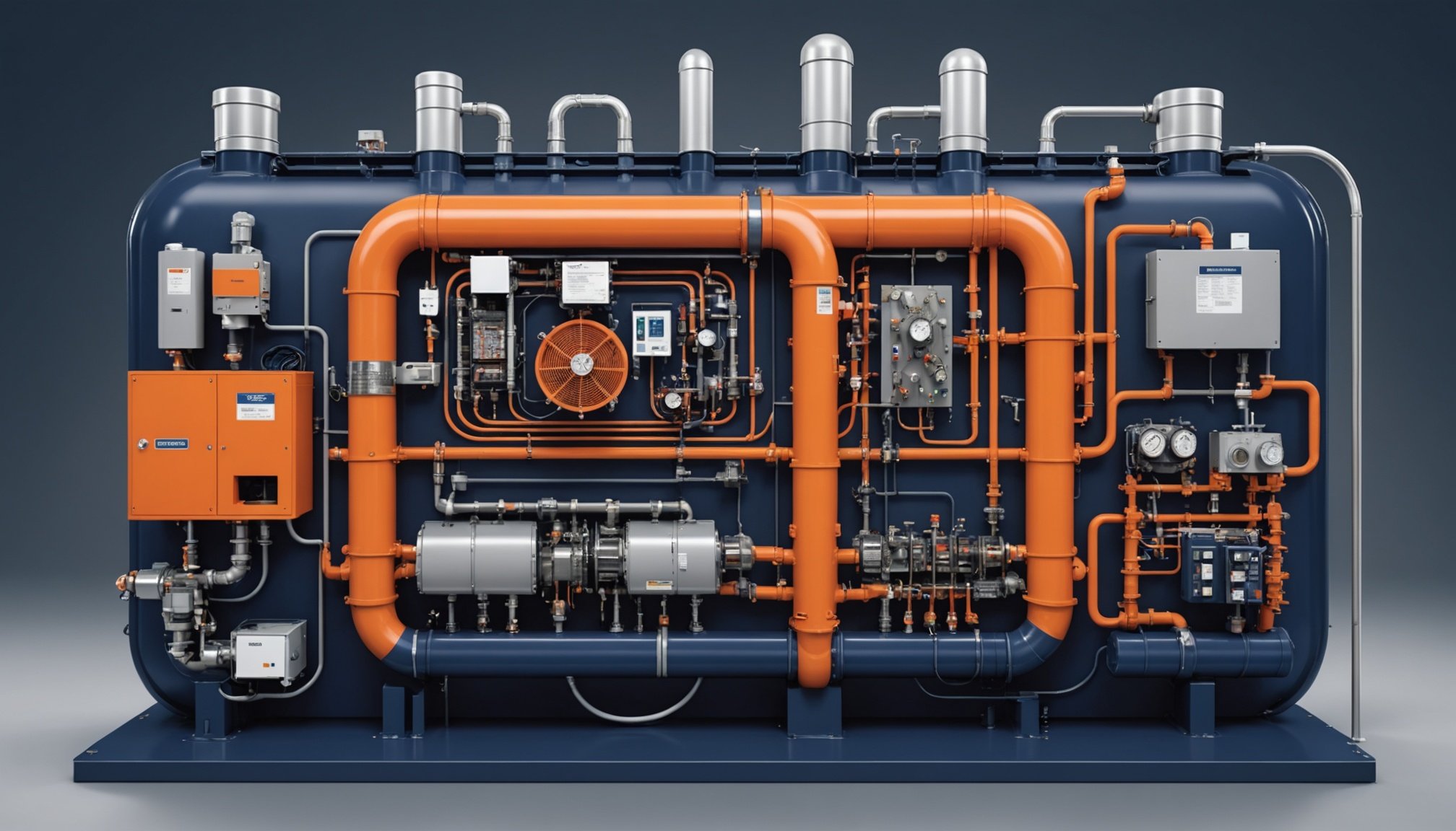
Factory Charge and Line-Set Adjustment: Why Total Charge Depends on Liquid Line Volume
Split-system refrigerant charge equals factory charge plus line-set adjustment, where the adjustment compensates for liquid line internal volume beyond the factory-included length per manufacturer Long Line Guideline (LLG). The complete relationship: Total Charge = Factory Charge ± [(Actual Length − Factory Length) × Per-Foot Rate], where the sign is positive for line sets longer than factory length and negative for shorter runs.
Outdoor condensing units ship factory-charged for the condenser coil plus a standard line-set length: typically 15 ft (4.6 m) per Carrier and Goodman LLGs, 25 ft (7.6 m) for many mini-splits. The liquid line carries dense liquid refrigerant at approximately 1,100 kg/m³ for R-410A, holding most of the additional charge for any length beyond factory allowance. The suction line carries low-density vapor, contributing negligible charge on standard residential runs. The charge adjustment formula per Goodman GSXC16 R-410A LLG:
RA (oz) = (LA − 15) ft × 0.6 oz/ft
where RA equals refrigerant adjustment, LA equals actual liquid line length in feet, 15 equals the factory-included length, and 0.6 oz/ft is the per-foot rate for 3/8" (9.5 mm) liquid line.
Per HVAC-Talk forum thread 1815791 senior technician commentary, the most common new-install error is either forgetting to add refrigerant for line sets beyond factory length, or adding charge for the entire line length instead of only the additional footage beyond the factory allowance. This calculator computes total refrigerant charge from factory charge, line-set length, liquid line diameter, and refrigerant type per manufacturer LLG methodology, outputting weigh-in charge weight in oz/lb or g/kg. The output complements the Superheat & Subcooling Calculator: this sibling calculates charge during install (weigh-in by length); the pillar verifies charge after install (superheat/subcooling field readings).
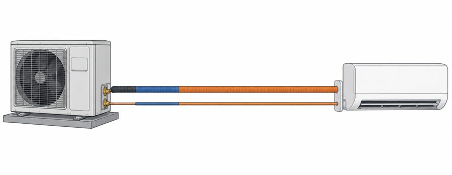
Total charge = factory charge + line-set adjustment. The factory charge covers the condenser and the first 15 ft (4.6 m) of line set; every foot of 3/8" (9.5 mm) liquid line beyond that adds 0.6 oz/ft (55.8 g/m) per manufacturer Long Line Guideline.
Calculator Inputs: Factory Charge, Line-Set Length, Liquid Line Diameter, Refrigerant Type
The calculator processes five inputs to compute line-set adjustment and total weigh-in charge.
Input 1: Refrigerant Type — R-410A, R-32, R-22, R-134a, R-454B per ASHRAE Standard 34-2022. Determines per-foot charge rate because rate scales with refrigerant liquid density.
Input 2: Factory Charge — from outdoor unit nameplate or Product Data sheet in oz/lb or g/kg. Typical residential: 6-12 lb (96-192 oz / 2.7-5.4 kg) for 2-5 ton systems.
Input 3: Factory-Included Line-Set Length — from installation manual in ft or m. Typical values: 15 ft (4.6 m) for Carrier and Goodman; 25 ft (7.6 m) for many mini-splits.
Input 4: Actual Line-Set Length — measured one-way from outdoor service valve to indoor connection, including vertical rises and horizontal runs in ft or m. Typical residential and light commercial range: 15-150 ft (4.6-45.7 m).
Input 5: Liquid Line Diameter — 1/4", 5/16", 3/8", or larger OD in inch or mm. Determines per-foot rate.
Calculator outputs: line-set adjustment (oz or g), total charge, and weigh-in target weight (lb/oz or kg/g).
Charge Adjustment (oz) = (L_actual − L_factory) × R_perfoot
Total Charge (oz) = Factory Charge (oz) + Charge Adjustment (oz)
Total Charge (lb) = Total Charge (oz) / 16
SI: Charge Adjustment (g) = (L_actual − L_factory)(m) × R_perfoot(g/m)
Per-foot charge rates by liquid line diameter for R-410A per manufacturer LLG:
| Liquid Line OD | Per-Foot Rate (oz/ft) | Per-Foot Rate (g/m) | Application |
|---|---|---|---|
| 1/4" (6.4 mm) | 0.23 | 21.4 | Small mini-split |
| 5/16" (7.9 mm) | 0.40 | 37.2 | Mini-split / small AC |
| 3/8" (9.5 mm) | 0.60 | 55.8 | Standard residential |
| 1/2" (12.7 mm) | 1.20 | 111.6 | Large residential / light commercial |
| 5/8" (15.9 mm) | 1.84 | 171.1 | Light commercial |
Variable ranges: Factory Charge 96-192 oz (2.7-5.4 kg) for 2-5 ton residential; L_factory 15-25 ft (4.6-7.6 m) per manufacturer; L_actual 15-150 ft (4.6-45.7 m) typical; R_perfoot 0.23-1.84 oz/ft (21.4-171.1 g/m) by diameter; Total Charge 100-400 oz (2.8-11.3 kg) typical.
Conversion factors per NIST: 1 oz = 28.35 g; 1 lb = 16 oz = 0.4536 kg; 1 oz/ft = 92.97 g/m; 1 ft = 0.3048 m; 1 inch = 25.4 mm.
Per HVAC-Talk thread 1815791 best practice: weigh in charge for new installs using a CPS charging scale rather than charging by pressure alone; weigh-in eliminates ambiguity from ambient conditions affecting superheat/subcooling during initial startup. R-454B note per plumbingsupplyandmore: R-454B liquid density runs 5-10% lower than R-410A; scale per-foot rates proportionally or use the manufacturer R-454B-specific LLG.
Liquid Line Charge Rate: Ounces per Foot by Diameter and Refrigerant Density
Per-foot charge rate scales with liquid line internal cross-sectional area (diameter squared) and refrigerant liquid density per plumbingsupplyandmore charge calculation methodology. Diameter dominates the relationship: a 1/4" (6.4 mm) line adds 0.23 oz/ft (21.4 g/m), while a 1-1/8" line exceeds 6 oz/ft (558 g/m).
The physics per plumbingsupplyandmore: charge per foot equals liquid line internal volume per foot multiplied by refrigerant liquid density. Internal volume scales with d² (cross-sectional area = π × r²), so the 1/4" to 3/8" diameter increase (1.5× diameter) produces approximately 2.6× charge per foot (0.23 → 0.60 oz/ft).
Liquid line internal volume per foot by OD per copper tube ACR dimensions:
| Liquid Line OD | ID (approx) | Internal Volume (in³/ft) | R-410A Charge (oz/ft) |
|---|---|---|---|
| 1/4" (6.4 mm) | 0.190" (4.8 mm) | 0.34 | 0.23 |
| 5/16" (7.9 mm) | 0.248" (6.3 mm) | 0.58 | 0.40 |
| 3/8" (9.5 mm) | 0.311" (7.9 mm) | 0.91 | 0.60 |
| 1/2" (12.7 mm) | 0.430" (10.9 mm) | 1.74 | 1.20 |
| 5/8" (15.9 mm) | 0.545" (13.8 mm) | 2.80 | 1.84 |
Refrigerant liquid density comparison per ASHRAE Fundamentals 2021 Chapter 30 at typical liquid line conditions of 105°F (40.6°C):
| Refrigerant | Liquid Density (lb/ft³) | Liquid Density (kg/m³) | 3/8" Rate (oz/ft) |
|---|---|---|---|
| R-410A | 65.9 | 1,056 | 0.60 |
| R-32 | 60.3 | 966 | 0.55 |
| R-454B | 61.5 | 985 | 0.56 |
| R-22 | 71.8 | 1,150 | 0.65 |
| R-134a | 73.9 | 1,184 | 0.67 |
Per plumbingsupplyandmore: R-454B runs 5-10% less dense than R-410A, so generic R-410A tables overstate R-454B charge by 5-10%; use manufacturer R-454B-specific LLG to avoid overcharge.
Suction line per-foot rate per plumbingsupplyandmore: the suction line carries low-density vapor, with per-foot rate of 0.02-0.81 oz/ft depending on OD. A 3/8" (9.5 mm) suction line contributes approximately 0.04 oz/ft (3.7 g/m), negligible for standard residential runs. A 7/8" (22.2 mm) R-410A suction line contributes 0.81 oz/ft (75.3 g/m); significant on runs exceeding 80 ft (24.4 m).
Per Carrier Puron LLG absolute method to illustrate diameter dependency: 15 ft of 1/4" liquid line produces (0.27 oz/ft × 15 ft) − 9 oz factory = −4.95 oz (remove 4.95 oz, because 1/4" holds less than the factory 3/8" assumption); 45 ft of 5/16" liquid line produces (0.40 oz/ft × 45 ft) − 9 oz factory = 9 oz (add 9 oz). Note: Carrier Puron LLG uses the absolute method (total line charge minus factory 9 oz); Goodman uses the incremental method (additional length beyond 15 ft times rate). Both are valid when applied to the equipment-specific LLG.
Critical fittings adjustment per plumbingsupplyandmore Field Charge methodology: add 10-20% to calculated line charge for fittings, using the lower percentage for simple runs and higher for complex configurations with multiple elbows or traps.
Weigh-In Procedure: Recovery, Evacuation to 500 Microns, and Scale-Measured Charge
Weigh-in charging via calibrated scale is the manufacturer-preferred method for new installs per York Central Tech Talk and HVAC-Talk thread 1815791, eliminating ambient-condition ambiguity that affects superheat/subcooling during initial startup.
Step 1: Recovery (if existing refrigerant is present). Recover existing charge per EPA Section 608 recovery requirements to manufacturer-specified vacuum level. Weigh recovered refrigerant to verify against expected charge as a diagnostic check.
Step 2: Evacuation. Evacuate system to 500 microns per AHRI Guideline N. Hold vacuum 15 or more minutes; a rise above 500 microns indicates a leak or residual moisture. Triple evacuation for systems with suspected moisture contamination.
Step 3: Calculate total charge. Total = factory charge (nameplate) + line-set adjustment [(actual − factory length) × per-foot rate]. Account for liquid line diameter, length beyond factory, and fittings (10-20% adder).
Step 4: Weigh-in via charging scale. Use a CPS charging scale or equivalent rated at ±0.25 oz (±7 g) accuracy per HVAC-Talk thread 1815791. Charge liquid refrigerant to the outdoor unit liquid service port for speed and to prevent fractionation in zeotropic blends. Monitor continuously; stop at the calculated total charge.
Step 5: Verify. Start system, run 15 or more minutes to stabilize. Verify subcooling 10-15°F (5.6-8.3°C) per manufacturer target. Fine-tune charge if subcooling falls outside target.
Zeotropic blend charging caution per ASHRAE Standard 34-2022: R-454B and R-407C are zeotropic blends of multiple components with different boiling points. Charging from the vapor space of a zeotropic cylinder removes lighter components first, changing blend composition through fractionation. Always charge zeotropic blends as liquid: invert the cylinder or use a dip-tube cylinder so liquid exits at the valve.
Per York Central Tech Talk weigh-in methodology: "the best way to charge a new install is to always WEIGH the charge into the unit." Operating charge varies by manufacturer; read installation instructions to determine what the factory charge includes (condenser only, or condenser plus standard line set).
Per HVAC-Talk thread 1815791: charging by weight (factory plus line-set adjustment) provides the baseline; subcooling/superheat verification confirms it. The two methods are complementary: weigh-in establishes charge, field readings verify it.
Suction Line and Vertical Lift Adjustments per Manufacturer Long Line Guideline
Beyond liquid line length, suction line diameter and vertical lift require additional charge adjustments per manufacturer LLG for long line applications, typically those exceeding 80 ft (24.4 m) equivalent length.
Suction line charge adjustment per Carrier/Goodman R-410A LLG: suction line vapor density is low, making adjustment negligible for standard residential runs. Per Goodman R-410A LLG, for 1-1/8" (28.6 mm) suction line diameter and/or lineal length over 150 ft (45.7 m), approximately 3 lb (1.4 kg) additional refrigerant may be needed to account for suction line volume. Most residential systems with suction runs under 80 ft (24.4 m) and 3/4" (19.1 mm) or smaller suction line require no suction adjustment.
Vertical lift subcooling requirement per Carrier Puron LLG: liquid line vertical lift causes pressure drop from static head and friction. Pressure drop risks liquid flashing to vapor before the metering device, producing capacity loss and TXV hunting. Minimum 10°F (5.6°C) subcooling is required for all liquid line diameters in long line applications. Add 5°F (2.8°C) subcooling for every 30 ft (9.1 m) of liquid line vertical lift per ACHR News.
Oil trap requirement per Goodman R-410A LLG: vertical suction line risers require oil traps to ensure oil return to the compressor. A trap at the indoor unit is required if elevation difference exceeds 80 ft (24.4 m); suction risers over 20 ft (6.1 m) may require intermediate traps per manufacturer specification.
Liquid line insulation per Daikin R-32 LLG: insulate any liquid line portion passing through areas more than 10°F (5.6°C) above ambient to prevent heat gain reducing subcooling. Never attach liquid line to bare suction line copper.
Equivalent length versus actual length per Carrier Puron LLG: fittings add equivalent length beyond physical measurement, approximately 1-2 ft (0.3-0.6 m) per elbow per ACR fitting tables. Long line qualification and charge adjustment are both based on equivalent length, not actual length.
Per HVAC-Talk thread 2240464 senior technician commentary: maximum line length varies dramatically by brand and model — Mitsubishi typically 200 ft (61 m), Fujitsu similar, Carrier 150 ft (45.7 m), lower-end units 30-50 ft (9.1-15.2 m). Always confirm maximum line length and charge adjustment from the manufacturer installation manual; exceeding the maximum risks oil return failure and compressor damage regardless of charge accuracy.
35-Foot Lennox Split System: Factory Charge Plus 12-Ounce Line-Set Adjustment
Project: 3-ton (36,000 BTU/hr / 10.55 kW) Lennox R-410A residential split system, new install. Outdoor condensing unit factory-charged for condenser coil plus 15 ft (4.6 m) of 3/8" (9.5 mm) liquid line. Actual line-set: 35 ft (10.7 m) of 3/8" liquid line, 7/8" (22.2 mm) suction line, 8 ft (2.4 m) vertical lift with outdoor unit below indoor.
Equipment specifications per Lennox installation manual: factory charge 8 lb 6 oz (134 oz / 3.8 kg) for condenser plus 15 ft (4.6 m) line set; per-foot rate 0.6 oz/ft (55.8 g/m) per Lennox LLG; factory-included length 15 ft (4.6 m); target subcooling 8-12°F (4.4-6.7°C) per data plate.
Step 1: Line-set adjustment.
Additional length beyond factory: 35 − 15 = 20 ft (10.7 − 4.6 = 6.1 m)
Charge adjustment = 20 ft × 0.6 oz/ft = 12 oz (6.1 m × 55.8 g/m = 340 g)
Per HVAC-Talk thread 1815791 documented case: "a 35 foot lineset is an extra 20 feet, multiply 20 by .6 to get 12 ounces. I would then weigh in 12 additional ounces of refrigerant via a CPS charging scale."
Step 2: Suction line and vertical lift check.
Suction line: 7/8" OD (22.2 mm), 35 ft (10.7 m). Per Goodman R-410A LLG, suction adjustment is negligible below 80 ft (24.4 m); no suction adjustment required. Vertical lift: 8 ft (2.4 m), well below the 30 ft (9.1 m) threshold requiring subcooling adjustment; below 80 ft (24.4 m) elevation difference, no oil trap required.
Step 3: Total charge.
Total charge = factory charge + line-set adjustment
Total = 134 oz + 12 oz = 146 oz (3,800 g + 340 g = 4,140 g)
Total = 146 / 16 = 9.125 lb = 9 lb 2 oz (4.14 kg)
Fittings adjustment per plumbingsupplyandmore: simple run with 2 elbows, add 10% to the line-set adjustment portion: 12 oz × 1.10 = 13.2 oz. Conservative practice rounds to 13 oz; total becomes 134 + 13 = 147 oz (4.17 kg). For this simple run, the 1 oz (28 g) difference is within scale tolerance; use 12 oz per Lennox LLG.
Step 4: Weigh-in procedure.
- Evacuate to 500 microns per AHRI Guideline N; hold 15 minutes, no rise.
- Connect CPS charging scale to R-410A cylinder (liquid charging — invert or use dip-tube cylinder).
- Charge liquid refrigerant to liquid service port.
- Factory charge 134 oz (3.8 kg) already in outdoor unit; add 12 oz (340 g) line-set adjustment.
- Total charge in system: 146 oz (4.14 kg).
Step 5: Subcooling verification.
Run system 15 minutes to stabilize at outdoor 90°F (32.2°C), indoor 75°F (23.9°C):
- Liquid line pressure: 365 psig (2,517 kPa) → R-410A saturation 110°F (43.3°C)
- Liquid line temperature: 100°F (37.8°C)
- Subcooling = 110 − 100 = 10°F (5.6°C) — within 8-12°F (4.4-6.7°C) target ✓
Step 6: Engineering decision.
Selected action: weigh in 12 oz (340 g) line-set adjustment beyond factory charge; 10°F (5.6°C) subcooling confirms correct total charge.
Per HVAC-Talk thread 1815791 debate resolution: the service tech who skips line-set adjustment ("check pressures and unless something appears off, add nothing") risks undercharge on longer line sets. The argument that "I've never noticed any significant changes in pressures or superheat/subcool after adding extra refrigerant" reflects that 12 oz (340 g) on a 134 oz (3.8 kg) charge is approximately 9%, shifting subcooling only 2-4°F (1.1-2.2°C) — easily masked by ambient variation during startup. Weigh-in eliminates this ambiguity: calculate the adjustment, weigh it in, verify subcooling.
Cost-benefit: proper weigh-in adds 5-10 minutes to the install. Undercharge from a skipped adjustment reduces capacity 5-10% per approximately 10% undercharge, raises energy consumption, and risks compressor overheating per ToolGrit. The 12 oz (340 g) adjustment costs $3-5 in refrigerant; repeated service callbacks and long-term efficiency loss cost far more over equipment life.
Long Line Applications: Oil Return, Crankcase Heaters, and Liquid Line Lift Limits
Line sets exceeding 80 ft (24.4 m) equivalent length qualify as long line applications per manufacturer LLG, requiring oil return management, crankcase heaters, and liquid line lift limits beyond standard charge adjustment.
Long line qualification per Carrier Puron/Goodman LLG: standard application at or below 80 ft (24.4 m) equivalent length; long line application above 80 ft (24.4 m); maximum allowable 150-250 ft (45.7-76.2 m) depending on equipment per HVAC-Talk thread 2240464.
Oil return management per Daikin R-32 LLG: compressor oil circulates with refrigerant; long lines plus vertical risers risk oil trapping. Suction riser velocity must exceed the minimum to carry oil upward, approximately 1,000-1,500 fpm (5.1-7.6 m/s). Oil traps at the base of suction risers are required; intermediate traps every 20 ft (6.1 m) vertical per manufacturer. Double suction risers are required for variable-capacity systems to maintain velocity at minimum compressor speed.
Crankcase heater requirement per Daikin R-32 LLG: systems with total charge over 12 lb (192 oz / 5.4 kg) require a crankcase heater (CCH) to prevent refrigerant migration to the compressor crankcase during off-cycle. Long line applications increase total charge, often crossing the 12 lb (5.4 kg) CCH threshold. Verify CCH is operable; do not disconnect.
Additional oil charge per Daikin R-32 LLG: systems over 20 lb (320 oz / 9.1 kg) refrigerant require 0.3 oz (8.5 g) POE oil per lb (0.45 kg) refrigerant over 20 lb. POE (Polyol Ester) oil is used in scroll compressors per Daikin specification.
Liquid line lift limit per Carrier Puron LLG: each foot of lift creates approximately 0.5 psi (3.4 kPa) static head pressure drop for R-410A liquid. Excessive lift causes flashing before the metering device; minimum 10°F (5.6°C) subcooling is required, with maximum lift typically 50-60 ft (15.2-18.3 m) for standard equipment per manufacturer.
Per HVAC-Talk thread 2240464 brand-specific limits: Mitsubishi typically 200 ft (61 m), Fujitsu similar, Carrier 150 ft (45.7 m), lower-end units 30-50 ft (9.1-15.2 m). Residential systems with LEV at the condenser typically limit to 80 ft (24.4 m); commercial 120 ft (36.6 m); premium variable-capacity up to 250 ft (76.2 m). Maximum line length and charge adjustment both come from the manufacturer manual; exceeding the maximum risks oil return failure regardless of charge accuracy.
Charge Verification After Weigh-In: Subcooling Confirmation per Manufacturer Target
Weigh-in establishes the calculated charge; subcooling verification confirms it per manufacturer target, closing the loop between calculation (this calculator) and verification (Superheat & Subcooling Calculator).
Verification workflow per manufacturer LLG and AC Service Tech methodology: after weigh-in, verify via subcooling for TXV systems or target superheat for fixed-orifice.
1. Run system 15 or more minutes to stabilize, with outdoor temperature above 65°F (18.3°C).
2. Verify indoor airflow at 350-450 CFM/ton per Manual D.
3. Measure subcooling (TXV) or target superheat (fixed-orifice) per Superheat & Subcooling Calculator.
4. Compare to manufacturer target: typically 10-15°F (5.6-8.3°C) subcooling for TXV systems.
Why verification follows weigh-in per HVAC-Talk thread 1815791: weigh-in calculates charge from line-set length, assuming standard liquid density at design conditions. Actual operating conditions (ambient temperature, indoor load) shift subcooling slightly from the calculated value. Subcooling verification confirms the weigh-in charge produces the correct refrigerant inventory. Fine-tune by a few ounces if subcooling falls outside the target range.
Long line subcooling adjustment per Carrier Puron LLG: long line applications require minimum 10°F (5.6°C) subcooling (versus standard 8-12°F / 4.4-6.7°C) to prevent flashing in the long liquid line before the metering device. Charge to 10°F (5.6°C) subcooling or rating plate subcooling, whichever is greater.
Discrepancy diagnosis per AC Service Tech: weigh-in correct but subcooling low — check for a leak or verify liquid line diameter assumption; weigh-in correct but subcooling high — liquid line shorter than assumed or a restriction is present; subcooling matches target — weigh-in confirmed.
Per HVAC-Talk thread 1815791 resolution: weigh-in and subcooling verification are complementary. Weigh-in provides the baseline charge, especially valuable when ambient conditions make field readings ambiguous during startup; subcooling verification confirms the result. Skipping either step introduces risk: weigh-in alone may not catch a leak; field readings alone may not catch undercharge masked by ambient variation. Calculate, weigh, verify.
Application Boundaries: Mini-Split Branch Boxes, Zeotropic Blends, and Maximum Line Limits
Refrigerant charge calculation per this methodology applies to single-evaporator split systems with known factory charge and line-set length, standard liquid line diameters from 1/4" to 5/8" (6.4-15.9 mm), and weigh-in charging for new installs.
Six conditions require analysis beyond the standard formula:
(1) Multi-zone mini-split branch boxes: multiple indoor heads share one outdoor unit through a branch box. Per pickHVAC, 4-5 ton multi-zone systems with 5-9 zones route refrigerant through the branch box; charge calculation requires adding per-head charge plus branch box internal volume per the manufacturer manual. The single-zone formula is inadequate.
(2) Zeotropic blend fractionation (R-454B, R-407C): charge as liquid to prevent composition shift per ASHRAE Standard 34-2022. R-407C has 9°F (5°C) temperature glide; charging vapor changes blend composition. Per-foot rates differ from R-410A (R-454B is 5-10% less dense).
(3) Maximum line length limits per HVAC-Talk thread 2240464: exceeding manufacturer maximum (150-250 ft / 45.7-76.2 m depending on brand) risks oil return failure regardless of charge accuracy. Verify maximum and charge adjustment from the installation manual.
(4) Variable-capacity and inverter systems: oil return at minimum capacity requires double suction risers per manufacturer. Charge calculation follows inverter-specific LLG; the standard formula may not account for variable refrigerant distribution.
(5) Heat pump liquid line sizing per Carrier Puron LLG: heat pump liquid lines are limited to 3/8" (9.5 mm) because the reversing valve requires consistent diameter, versus cooling-only systems allowing 1/4" and 5/16" lines. Use the heat-pump-specific LLG.
(6) Self-contained and factory-charged systems (window units, PTACs, packaged units): no field line-set; factory charge is complete. Charge calculation is not applicable; replace per nameplate weight if servicing.
Per manufacturer LLG methodology: charge calculation provides the weigh-in baseline; subcooling/superheat verification confirms it. The calculator computes line-set adjustment from length, diameter, and refrigerant type; engineering judgment applies manufacturer-specific LLG, maximum line limits, and long line accessories per the equipment installation manual.
Refrigerant Charge Calculator
Refrigerant charge calculation from factory charge, line-set length, liquid line diameter, and refrigerant type per manufacturer Long Line Guideline methodology, computing weigh-in charge weight (oz/lb or g/kg) with per-foot adjustment rates for R-410A, R-32, R-22, R-134a, and R-454B, available in the Refrigerant Charge Calculator.
Refrigerant Charge Calculator
Compute total refrigerant charge from factory charge and line-set length, with per-foot adjustment rates for R-410A, R-32, R-22, R-134a, and R-454B.
Open Refrigerant Charge CalculatorFAQ
Do I need to add refrigerant for a line set longer than 15 feet on a new install?
Per HVAC-Talk forum thread 1815791 senior technician methodology, yes — add refrigerant for line sets beyond the factory-included length. Lennox outdoor units (like most manufacturers) ship charged for the condenser coil plus 15 ft (4.6 m) of line set; for 3/8" (9.5 mm) liquid line, add 0.6 oz/ft (55.8 g/m) beyond the first 15 ft (4.6 m). Per the thread 1815791 documented example: "a 35 foot lineset is an extra 20 feet, multiply 20 by .6 to get 12 ounces. I would then weigh in 12 additional ounces via a CPS charging scale." The argument for skipping the adjustment overlooks that 12 oz (340 g) on a 134 oz (3.8 kg) charge is only 9%, shifting subcooling by 2-4°F (1.1-2.2°C) and easily masked by ambient variation during startup. Calculate the adjustment, weigh it in, then verify subcooling per manufacturer target.
What is the most accurate way to charge a new split-system install?
Per York Central Tech Talk weigh-in methodology, the most accurate approach is to always weigh the charge into the unit. The operating charge varies by manufacturer; read installation instructions to determine what the factory charge includes (condenser only, or condenser plus standard line set). Procedure: evacuate to 500 microns per AHRI Guideline N; calculate total charge (factory charge plus line-set adjustment); weigh in via charging scale rated at ±0.25 oz (±7 g) accuracy; verify subcooling per manufacturer target. Per York Central Tech Talk worked example: 1.84 oz/ft (171.1 g/m) for 5/8" line times 38 ft (11.6 m) additional = 69.92 oz / 16 = 4.37 lb (1.98 kg) additional refrigerant. Weigh-in eliminates ambient-condition ambiguity that affects superheat/subcooling during initial startup; field verification confirms the weighed charge.
How much does liquid line diameter affect refrigerant charge?
Per plumbingsupplyandmore charge calculation methodology, diameter has an enormous effect because per-foot charge scales with internal cross-sectional area (diameter squared). A 1/4" (6.4 mm) liquid line adds 0.23 oz/ft (21.4 g/m); a 3/8" (9.5 mm) line adds 0.60 oz/ft (55.8 g/m); a 1-1/8" line exceeds 6 oz/ft (558 g/m). The 1.5× diameter increase from 1/4" to 3/8" produces approximately 2.6× charge per foot because cross-sectional area scales with d². Refrigerant density also matters: R-454B runs 5-10% less dense than R-410A, so generic R-410A tables overstate R-454B charge by 5-10%. Always use manufacturer-specific tables and add 10-20% to the calculated line charge for fittings.
What is the maximum line set length for a mini-split? Does it vary by brand?
Per HVAC-Talk forum thread 2240464 senior technician commentary, maximum line length varies dramatically by brand and model: Mitsubishi typically allows 200 ft (61 m), Fujitsu similar, Carrier around 150 ft (45.7 m), and lower-end units 30-50 ft (9.1-15.2 m). Residential systems with LEV at the condenser typically limit to 80 ft (24.4 m); lower-end commercial to 120 ft (36.6 m); premium variable-capacity up to 250 ft (76.2 m). Beyond charge adjustment, long line sets require oil return management (suction riser velocity, oil traps), crankcase heaters for charge over 12 lb (5.4 kg), and minimum 10°F (5.6°C) subcooling to prevent liquid flashing. Always confirm both maximum line length and charge adjustment from the manufacturer installation manual; exceeding the maximum risks oil return failure and compressor damage regardless of charge accuracy.
Why do I have to charge R-454B and R-407C as liquid, not vapor?
Per ASHRAE Standard 34-2022 zeotropic blend classification, R-454B (1.4°F / 0.8°C glide) and R-407C (9°F / 5°C glide) are blends of multiple refrigerants with different boiling points. Charging from the vapor space of a zeotropic cylinder removes lighter components first, changing blend composition through fractionation. Per plumbingsupplyandmore Field Charge methodology, always charge zeotropic blends as liquid to maintain correct composition: invert the cylinder or use a dip-tube cylinder, and charge slowly through the liquid service port. R-410A is near-azeotropic (approximately 0°F / 0°C glide) and less sensitive to fractionation, but liquid charging remains best practice. R-32 is a single component with zero glide; vapor or liquid charging both maintain composition, though liquid is faster.
Related Calculators
Superheat and subcooling verification after weigh-in per AC Service Tech methodology: Superheat & Subcooling Calculator. Refrigeration cooling load from transmission, infiltration, product, and internal heat gains per ASHRAE Handbook Refrigeration: Refrigeration Load Calculator.
Duct sizing per ACCA Manual D friction loss methodology for companion air-side design: Duct Size Calculator. Required supply airflow (CFM) per Manual D verification before charge adjustment: CFM Calculator.
Chiller capacity from chilled-water flow and temperature difference for water-side refrigeration: Chiller Capacity Calculator. Refrigerant charge feeds equipment efficiency analysis: HVAC Efficiency Calculator. Cooling capacity in tons of refrigeration for system sizing context: AC Tonnage Calculator.