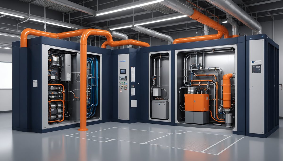
Cleanroom HVAC design failures typically manifest as non-compliance with ISO 14644-1 particle concentration limits, leading to product contamination, regulatory rejection, and facility shutdown. When engineers skip preliminary air change rate estimation, they risk undersizing supply airflow by an order of magnitude or more compared to actual requirements — applying commercial 4-12 ACH to a cleanroom that needs 240 ACH covers only ~3% of required airflow. This mismatch guarantees ISO classification failure and forces complete HVAC redesign mid-project.
This calculation provides the essential first-pass ventilation estimate that informs duct sizing, fan selection, and energy analysis before detailed particle transport modeling. Without this baseline, engineers cannot properly size HEPA filter banks, calculate pressure drop across terminal boxes, or determine make-up air requirements for pressurization control. The Cleanroom Air Change Rate Calculator implements the industry-standard heuristic mapping from ISO class to recommended ACH targets documented in IEST-RP-CC012 and ASHRAE Handbook Chapter 19.
Why Cleanroom ACH Differs from Commercial Ventilation Rates
Cleanroom air change rate (ACH) quantifies the volumetric air replacement frequency within a controlled environment, defined as the supply airflow divided by room volume. Unlike comfort ventilation governed by ASHRAE 62.1 occupancy rates, cleanroom ACH is driven by particle dilution requirements specified in ISO 14644-1:2015 Section 3.2. The standard defines nine cleanliness classes based on maximum allowable particle concentrations at specified sizes, with ISO 1 representing the cleanest environment (<10 particles/m³ at 0.1 μm) and ISO 9 equivalent to typical indoor air quality. Engineers need this parameter to establish the ventilation baseline that supports subsequent design decisions about airflow patterns, filter selection, and pressurization strategies.
The physical basis for high ACH values lies in particle transport dynamics. Airborne contaminants from personnel, processes, and equipment generate particles at rates measured in particles per minute per person — IEST-RP-CC003 documents approximately 100,000 particles/min ≥0.5 μm for a standing motionless gowned operator, rising to 1-5 million particles/min for moderate-to-heavy work activity, with ungowned personnel generating substantially more. The ventilation system must provide sufficient air changes to dilute these sources below ISO concentration limits while accounting for filter efficiency and airflow uniformity. For ISO Class 5 cleanrooms (formerly Class 100), typical ACH ranges of 150-350 represent 30-70 times higher ventilation than standard commercial spaces. This extreme ventilation requirement drives fan power consumption to 40-90 kW for a 200 m³ ISO 5 cleanroom (depending on Specific Fan Power per ASHRAE 90.1 Section 6.5.3.1), compared to under 1 kW for an equivalent commercial space at 6 ACH.
Cleanroom ACH connects to adjacent calculations in HVAC sizing. The CFM calculation for HVAC ventilation covers fan and duct sizing once the supply airflow is known; the air changes per hour calculation is the inverse — useful for verifying that an as-built system meets its target classification. HEPA filter pressure drop of 250-375 Pa clean (rising to 500 Pa loaded) dominates the static pressure budget for cleanroom AHUs.
The ISO Class → ACH Heuristic and Volumetric Conversion
Supply Airflow (m³/h) = Recommended ACH × Room Volume (m³)
Supply Airflow (CFM) = Supply Airflow (m³/h) / 1.699
The formula begins with a heuristic lookup that maps ISO 14644-1 class to recommended ACH target. The variable isoClass represents the target cleanliness classification from 1 (strictest) to 9 (least stringent). Each integer corresponds to specific particle concentration limits defined in ISO 14644-1 Table 1. The lookup table implements industry practice documented in IEST-RP-CC012 Section 6.2.2, which provides ACH ranges for different cleanroom applications. The achLookup variable represents the midpoint of these ranges, providing a starting point for preliminary design.
The recommendedACH variable represents the mapped air change rate in changes per hour. For ISO Class 5, this value is 240 ACH, which falls within the typical industry range of 150-350 ACH for mixed-flow cleanrooms. This ACH value must be adjusted based on specific contamination sources, with semiconductor fabrication requiring higher values (300-350 ACH) than pharmaceutical compounding (150-240 ACH). The implication: at 240 ACH, mean air residence time is 15 seconds (3,600 / 240), providing rapid dilution of particle generation from process equipment.
Room volume (roomVolume) represents the total controlled space in cubic meters or cubic feet. Only the actual cleanroom volume should be used, excluding adjacent spaces or plenums. Typical cleanroom volumes range from 50 m³ for small ISO 7 compounding rooms to 5,000 m³ for ISO 5 semiconductor bays. The multiplication with recommended ACH yields supplyAirflowM3h, the volumetric airflow rate in cubic meters per hour required to achieve the target air change frequency. This value directly determines fan sizing, with ISO 5 cleanrooms requiring 12,000-24,000 m³/h for a 100 m³ room.
Convert to CFM with the factor 1.699 m³/h per CFM for North American equipment specification, where fans and air handlers are rated in CFM. The resulting CFM value informs duct sizing per SMACNA HVAC Duct Construction Standards, with typical velocities of 5-8 m/s for main ducts and 2.5-3.5 m/s for terminal branches. The formula assumes standard air density of 1.2 kg/m³ at sea level; high-altitude installations need altitude correction in HVAC to adjust mass flow and HEPA filter performance at reduced air density.
Pharmaceutical ISO 5 Filling Room: 240 m³ → 57,600 m³/h
Consider an ISO Class 5 cleanroom for pharmaceutical aseptic filling operations. The room dimensions are 10 m × 8 m × 3 m (L × W × H), providing a volume of 240 m³. This represents a typical intermediate-scale filling suite where product exposure occurs under unidirectional airflow. The target classification requires maintaining particle counts below 3,520 particles/m³ at 0.5 μm during operational state.
Metric Calculation:
ISO Class 5 maps to recommended ACH = 240
Room Volume = 240 m³
Supply Airflow = 240 × 240 = 57,600 m³/h
Imperial Calculation:
Room Volume = 240 m³ × 35.315 = 8,476 ft³
Supply Airflow = 57,600 m³/h ÷ 1.699 = 33,902 CFM
Practical takeaway: 57,600 m³/h (33,902 CFM) is the screening estimate for ISO Class 5 pharmaceutical filling — 240 ACH at the upper end of the IEST-RP-CC012 range for pharma applications (150-240 ACH). For aseptic processing per EU GMP Annex 1, the room must operate as Grade A under unidirectional airflow with 80-100% HEPA ceiling coverage, maintaining 0.45 m/s ±20% face velocity through the filters. Cross-check: at 240 m² ceiling area (assumes full coverage at 80×30 m room), required filter face velocity = 57,600 / (240 × 0.80 × 3,600) = 0.083 m/s — well below the 0.45 m/s target, indicating either filter area can be reduced (smaller bank) or the design needs higher ACH to hit unidirectional velocity. This is the iterative balance the screening number alone does not resolve.
Semiconductor ISO 3 Photolithography: 900 m³ → 360,000 m³/h
For a semiconductor fabrication facility, consider an ISO Class 3 photolithography bay measuring 20 m × 15 m × 3 m, with a volume of 900 m³. This environment requires extreme cleanliness to prevent defects on silicon wafers during photoresist processing. ISO Class 3 limits particle counts to 35,200 particles/m³ at 0.1 μm, necessitating unidirectional airflow with ULPA filtration.
Metric Calculation:
ISO Class 3 maps to recommended ACH = 400
Room Volume = 900 m³
Supply Airflow = 400 × 900 = 360,000 m³/h
Imperial Calculation:
Room Volume = 900 m³ × 35.315 = 31,784 ft³
Supply Airflow = 360,000 m³/h ÷ 1.699 = 211,889 CFM
Practical takeaway: 360,000 m³/h (211,889 CFM) requires either multiple parallel air handlers (typically 4-6 units of 60,000 CFM each) or a central system with extensive trunk ductwork. The 6× airflow versus the pharmaceutical example for 3.75× the volume reflects the much stricter ISO Class 3 requirement (400 ACH vs 240 ACH). At this airflow, fan motor heat alone (estimated 80-150 kW for system efficiency 50-65%) becomes a significant cooling load that adds to process equipment heat — design the chilled-water cooling for both contributions. Verify the assumed 400 ACH against semiconductor industry-specific guidance per IEST-RP-CC012.3, which typically specifies 350-500 ACH for active photolithography bays depending on tool density.
What Adjusts the Mapped ACH in Practice
ISO Classification and Application-Specific Requirements
The ISO class selection drives the ACH lookup value, but within each class, specific applications demand adjustments. Semiconductor cleanrooms typically operate at the upper end of ACH ranges due to high particle generation from chemical mechanical planarization and etching processes. Pharmaceutical cleanrooms may use lower ACH values within the range when employing advanced gowning protocols and minimizing personnel movement. Medical device assembly rooms often fall in the middle, balancing contamination control with operational flexibility. Engineers must consult IEST-RP-CC012.3 Table 2 for application-specific guidance, which recommends 300-350 ACH for ISO Class 5 semiconductor bays versus 150-240 ACH for ISO Class 5 pharmaceutical filling.
Actual particle generation rates vary by process: a single gowned operator generates approximately 100,000 particles/min ≥0.5 μm during moderate activity, while automated equipment may generate 1,000,000 particles/min. These source terms directly impact the required ACH through the contamination balance equation. The calculator's heuristic approach assumes typical source terms; for facilities with unusual processes or high personnel density, engineers should increase the ACH by 20-50% above the mapped value. This adjustment ensures adequate dilution capacity during peak operational states.
Airflow Pattern and Filter Coverage
Unidirectional (laminar) airflow patterns allow lower ACH values to achieve equivalent particle control compared to non-unidirectional (turbulent) flow. For ISO Class 5, unidirectional flow with 100% HEPA ceiling coverage can maintain classification with 150-200 ACH, while mixed flow may require 240-350 ACH. The physical mechanism involves direct particle sweeping versus random dilution. Unidirectional flow creates predictable particle trajectories that transport contaminants to returns, reducing residence time by 50-70% compared to turbulent mixing.
Filter efficiency and coverage percentage modify the effective ACH. HEPA filters (99.97% at 0.3 μm) remove most particles on each pass, while ULPA filters (99.999% at 0.12 μm) provide superior removal for ISO 1-3 applications. Partial filter coverage (40-60% of ceiling area) requires higher face velocities to maintain unidirectional flow, increasing pressure drop and fan power. Engineers must calculate the actual airflow pattern using computational fluid dynamics or empirical correlations from ISO 14644-4 Annex B. The calculator assumes typical filter coverage of 80% for ISO 1-5 and 40% for ISO 6-9.
Room Geometry and Air Distribution
Room aspect ratio and ceiling height affect airflow distribution efficiency. Long, narrow rooms (aspect ratio >3:1) may develop dead zones at corners despite adequate ACH, requiring localized airflow increases of 10-20%. Low ceiling heights (<2.5 m) constrain filter placement and may necessitate higher ACH to compensate for reduced plenum space. The calculator assumes ideal geometry with height-to-width ratios between 1:2 and 1:4; for non-ideal spaces, engineers should apply geometric correction factors from ASHRAE Handbook Chapter 19 Table 7.
Obstructions from process equipment create localized turbulence that reduces effective air changes. Semiconductor tools with large footprints can block 30-50% of airflow, creating recirculation zones with particle accumulation. The calculator assumes minimal obstructions; for equipment-intensive cleanrooms, engineers must perform obstruction analysis per IEST-RP-CC012.4 Section 5.3. This may require increasing the calculated airflow by 25-40% or implementing targeted ventilation around critical zones.
Where the ISO Class → ACH Heuristic Falls Short
The fixed lookup table is a screening tool. Five conditions push real cleanroom design beyond what the heuristic captures:
-
ISO classification is determined by measurement, not calculation. ISO 14644-1:2015 Section 4.2 explicitly states that classification is based solely on measured particle concentrations per ISO 14644-3 test methods. Achieving 240 ACH does not guarantee ISO 5 — only validated particle counts at the specified sampling locations do. Treat the calculator output as a sizing input, not as compliance evidence.
-
Application within class spans a wide range. ISO 5 pharmaceutical filling typically operates at 150-240 ACH; ISO 5 semiconductor processing typically requires 300-350 ACH. The calculator returns the midpoint of one range; for actual design, consult IEST-RP-CC012 Table 2 with the specific application and adjust accordingly.
-
No source-term analysis. The heuristic does not account for personnel count, process equipment particle generation, or activity intensity. A room with 5 active operators and high-particle process equipment may need 50% more airflow than the heuristic returns; a quiet, low-personnel room may operate adequately at 70% of the heuristic value. Use IEST-RP-CC003 source-term data to refine when source terms differ materially from typical.
-
Airflow pattern fundamentally changes ACH requirement. Unidirectional (laminar) airflow with full HEPA ceiling coverage allows lower ACH for the same classification because of direct particle sweeping; non-unidirectional (mixed/turbulent) flow requires higher ACH for equivalent dilution. ISO 14644-4 Annex B provides design guidance on pattern selection, which the calculator does not address.
-
Pressurization and makeup air not included. Cleanrooms require positive pressure relative to surrounding spaces (typically +12-15 Pa per ISO 14644-4) — this requires 5-15% additional makeup airflow beyond the calculated supply rate to compensate for envelope and door-opening losses. Add the makeup air component to the calculator output for total system airflow specification.
Where Cleanroom ACH Calculations Go Wrong
Treating the calculator output as ISO compliance verification represents a fundamental misunderstanding of cleanroom classification. ISO 14644-1:2015 Section 4.2 explicitly states that classification is based solely on measured particle concentrations per ISO 14644-3 test methods. An engineer who assumes that achieving 240 ACH guarantees ISO Class 5 compliance will fail validation when particle counts exceed limits due to poor airflow uniformity or inadequate filtration. This mistake leads to costly rework, including additional HEPA filters, airflow pattern modifications, or complete system redesign after construction completion.
Mixing ISO classes with EU GMP Annex 1 grades causes specification errors in pharmaceutical projects. EU GMP Grade A corresponds approximately to ISO 5 in operation (and ISO 4.8 at rest); Grade B to ISO 7 in operation; Grade C to ISO 8 in operation; Grade D to ISO 9. The mappings are approximate at the 0.5 μm size, and EU GMP adds a 5 μm criterion that ISO 14644-1:2015 made optional. An engineer specifying "ISO 5" without confirming whether the project follows EU GMP Annex 1 or ISO 14644 alone may receive equipment designed for one standard but classified against the other. For pharmaceutical projects, always specify both the ISO class and the GMP grade, with reference to the operational vs at-rest state.
Using gross building volume instead of actual cleanroom volume results in 20-40% airflow oversizing. Engineers sometimes include adjacent gowning rooms, airlocks, or service corridors in the volume calculation, particularly when working from architectural drawings without clear demarcation. This error increases capital costs for larger fans, ducts, and filters while raising operational energy consumption by 15-30%. Proper volume measurement requires subtracting non-controlled spaces and accounting for equipment footprints that reduce effective air volume.
Try the Cleanroom Air Change Rate Calculator
Use our free online calculator to perform this calculation instantly.
Open Cleanroom Air Change Rate CalculatorACH Verification Workflow Before Detailed Design
For ISO Class 5 and cleaner applications, engineers should verify that calculated ACH values support unidirectional airflow velocities of 0.45 m/s ±20% through HEPA filters. When the calculated airflow divided by filter area yields velocities below 0.36 m/s, either increase the ACH by 25% or expand filter coverage to maintain proper airflow patterns. This threshold ensures adequate particle sweeping while minimizing turbulence at the filter face, balancing contamination control with energy efficiency.
Use the calculator during preliminary design phase to establish ventilation baselines before detailed particle transport modeling. The output informs fan sizing, duct layout, and filter bank configuration. After obtaining the estimated airflow, proceed to pressure drop calculations for HEPA filters (typically 250-375 Pa clean), duct system static pressure (100-250 Pa), and total external static pressure for fan selection. Combine this with thermal load calculations from process equipment to size cooling coils and determine supply air temperature requirements for complete HVAC system design.
FAQ
How do I calculate the air change rate for a cleanroom?
Multiply the ISO class mapped ACH value by the room volume in cubic meters to get supply airflow in m³/h. For ISO Class 5, the standard heuristic is 240 ACH; for a 100 m³ room, this gives 24,000 m³/h (14,126 CFM). Divide by 1.699 to convert to CFM for North American equipment. This screening value must be verified against actual particle counts per ISO 14644-3 before claiming classification compliance.
What ACH is required for an ISO 5 cleanroom?
ISO 14644-1 does not mandate a specific ACH value — it defines particle concentration limits that must be met by measurement. Industry guidance in IEST-RP-CC012 recommends 150-240 ACH for pharmaceutical ISO 5 rooms and 300-350 ACH for semiconductor ISO 5 bays. Non-unidirectional (mixed-flow) designs require the upper end; unidirectional airflow with full HEPA ceiling coverage can achieve the same classification at the lower end.
What is the difference between ISO 14644-1 and EU GMP Annex 1 cleanroom grades?
ISO 14644-1 defines nine classes (ISO 1-9) based on particle concentration limits at multiple sizes. EU GMP Annex 1 defines four grades (A, B, C, D) with both operational and at-rest limits, primarily for pharmaceutical manufacturing. Grade A approximates ISO 5 in operation; Grade B approximates ISO 7; Grades C and D approximate ISO 8 and ISO 9. Pharmaceutical projects must specify both the ISO class and GMP grade, along with the operational state being verified.
How does room volume affect cleanroom airflow requirements?
Supply airflow scales linearly with room volume: doubling the volume at the same ISO class doubles the required airflow. A 100 m³ ISO 7 room needs 6,000 m³/h (60 ACH); a 200 m³ ISO 7 room needs 12,000 m³/h. Engineers should use only the actual cleanroom volume, excluding gowning rooms, airlocks, and plenums, which are sized independently.
Can standard commercial ventilation rates be used for cleanroom design?
No. Commercial ventilation under ASHRAE 62.1 targets 4-12 ACH for occupant dilution; cleanrooms require 60-600 ACH for particle control — a 10× to 150× difference. Applying commercial rates to a cleanroom covers only 2-5% of the required airflow and guarantees ISO classification failure regardless of filter efficiency. The fundamental driver differs: commercial ventilation addresses CO₂ and odor; cleanroom ventilation must hold submicron particle concentrations below 3,520/m³ (ISO 5) to fewer than 10/m³ (ISO 1).
Related Calculators
- Cleanroom Air Change Rate Calculator — ISO class to ACH heuristic with Metric/Imperial output
- CFM Calculator for HVAC Ventilation — Fan and duct sizing from supply airflow
- Air Changes per Hour Calculator — Inverse calculation for verifying as-built systems
- Altitude Correction for HVAC — Air density adjustment for high-elevation cleanrooms