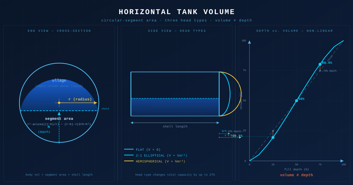
A horizontal cylindrical tank stores fuel oil, process water, or chemical feedstock, and whoever needs to know how much is inside reaches for a gauge stick or a level transmitter and reads a depth. The depth number looks straightforward until the calculation begins: a horizontal cylinder does not give volume in proportion to depth, and interpreting a dip reading as a straight percentage produces errors that are largest exactly where they matter most, near empty and near full. This article covers the geometry that converts a fill depth to a liquid volume, the three head types and what they add, shell length versus overall length, ullage, and where the ideal-geometry formula ends and the calibrated strapping table begins.
Why Depth Does Not Map to Volume in a Horizontal Tank
The single fact that makes a horizontal tank its own problem is that liquid volume is not proportional to depth: a cylinder lying on its side has a circular cross-section, so as the liquid rises the surface width changes, and a dip reading interpreted as a straight percentage is wrong everywhere except the exact midpoint.
Stand a vertical cylinder upright and the liquid surface is a full circle at every height, so each millimetre of depth adds the same cross-sectional area (πr²) and volume tracks depth linearly. Lay the same cylinder on its side and the liquid surface becomes a chord across the circular cross-section. At the very bottom, that chord starts as a narrow strip; it widens to the full diameter at the centreline, then narrows again approaching the top. The wetted cross-section is a circular segment whose area grows slowly near the bottom, quickly through the middle, and slowly again near the top. At a quarter of the diameter depth the tank holds only about 19.6% of the cylindrical body, not 25%. Volume equals that segment area times the shell length.
The calculator converts a measured fill depth into liquid volume through the circular-segment area, adds the head contribution by type (flat, hemispherical, or 2:1 elliptical), and reports capacity, percent full, and ullage. It is exact geometry for a true cylinder, appropriate for design, estimation, and planning. For inventory of record or custody transfer, a tank's calibrated strapping table, built by physical measurement under API MPMS procedures and corrected for temperature, governs. This closes the Plumbing cluster: where the pipe articles carried fluids, this one measures what the tanks hold.
Calculator Inputs: Diameter, Length Basis, Head Type, Liquid Depth
The calculator accepts eight inputs that together describe the tank geometry and the current fill state.
Unit System. US Customary (inches, gallons) or Metric (metres, litres). All formulas apply in either system; select the units matching the tank drawings or gauge-stick markings.
Tank Inside Diameter [in or m]. The interior diameter of the cylindrical shell. Inside, not outside. Wall thickness of 6–25 mm (0.25–1 in) on a pressure vessel overstates the effective volume if the outside diameter is entered. A nominal 2-metre (78.7-in) tank with 12 mm wall has inside diameter 1.976 m (77.8 in), representing a 2.4% volume difference.
Tank Length [in or m]. The straight shell length between the heads, or the overall end-to-end length. Enter whichever dimension the drawing provides, and set the Length Basis accordingly.
Length Basis. Shell length (the straight cylindrical section between the tangent lines) or overall length (end-to-end including the projecting head depth on each side). When overall length is entered, the calculator subtracts the head depths to recover the shell length before computing body volume.
Head Type. Flat (closing plate, no added volume), hemispherical (two half-spheres, largest addition), or 2:1 elliptical (ASME BPVC Section VIII standard, depth D/4 per head, half the hemispherical addition). The choice changes both total capacity and partial-fill volume at any given depth.
Liquid Depth [in or m]. The distance from the inside bottom of the shell to the liquid surface, measured by gauge stick, sight glass, or level transmitter. This is the inside liquid depth; external gauge readings that reference the shell outside or a datum offset must be converted before entry.
Output Volume Unit. US gallons, litres, oil barrels (42 US gal), cubic feet, or cubic metres. Select the unit matching the tank duty: fuel oil in barrels, process water in cubic metres, domestic storage in US gallons.
Target Volume [optional]. When a target fill volume is entered, the calculator reports current fill above or below target, giving a fill-short or fill-excess quantity rather than raw percent.
Outputs include: liquid volume at depth, total capacity, percent full, percent empty, ullage, cylindrical body volume at depth, combined head volume at depth, full head capacity, head share of total capacity, fill ratio h/D, circular segment area, and the length basis applied. The calculator does not account for out-of-roundness, longitudinal or transverse tilt, sump or sloped bottoms, sediment or water heel, internal deadwood (heaters or baffles), foam or floating roof, temperature correction for custody transfer (15°C/60°F per API MPMS Chapter 12), standard dished or torispherical heads (only flat, hemispherical, and 2:1 elliptical are supported), or depth-from-volume inverse calculation.
The Circular-Segment Area: Turning Depth into Wetted Area
The liquid at any depth fills a circular segment of the tank's cross-section, and the area of that segment is the geometric formula that converts a depth reading into a wetted area.
segment area = r² × arccos((r − h) / r) − (r − h) × √(2rh − h²)

where:
  r = tank radius (D/2) [m or in]
  h = liquid depth from the inside bottom [m or in]
  arccos in radians
  valid for 0 ≤ h ≤ D
The body volume follows directly:
body volume = segment area × shell length [m³ or in³]
The formula has two parts. The term r² × arccos((r − h)/r) gives the area of the circular sector swept from the tank centre to the chord at the liquid surface. The term (r − h) × √(2rh − h²) removes the triangular area between the chord and the tank centre, leaving the segment below the liquid surface. Together they give the exact wetted cross-section for any depth from 0 to D.
When h exceeds r (above the centreline), the term (r − h) is negative. The formula handles this automatically: the negative correction adds to the sector area rather than subtracting, correctly giving a segment larger than half the circle. The formula reaches its maximum at h = D where segment area equals the full circle area πr².
A worked check at the centreline (r = 1 m, h = r = 1 m):
segment area = 1² × arccos((1 − 1)/1) − (1 − 1) × √(2 × 1 × 1 − 1²)
             = 1 × arccos(0) − 0
             = π/2 = 1.5708 m²  (half the circle area πr² = π, for r = 1)
At h = r, arccos(0) = π/2, giving exactly half the full circle area. The centreline is the only depth where the body is exactly 50% full, a result of the formula's symmetry, not a special-case approximation.
Per standard geometry and API MPMS Chapter 2 (Tank Calibration) horizontal tank gauging references: the wetted cross-section is the circular segment of area r²·arccos((r−h)/r) − (r−h)·√(2rh−h²), and body volume is that area times the shell length. The formula uses radius, not diameter. Entering diameter where radius is required overstates the segment area by approximately a factor of four and produces an incorrect volume by the same ratio.
The Non-Linear Curve: 19.6 Percent at Quarter Depth, 50 at the Centreline
The percent-full versus depth relationship is an S-shaped curve that agrees with depth only at the centreline. Knowing its shape prevents the most common tank-gauging error.
Key values for the cylindrical body (heads excluded):
| Fill depth | Body volume fraction |
|---|---|
| h = 0 (empty) | 0% |
| h = D/4 (quarter depth) | 19.6% of body |
| h = D/2 (centreline) | Exactly 50% |
| h = 3D/4 (three-quarter depth) | 80.4% of body |
| h = D (full) | 100% |
The S-shape arises from how the cross-section changes with depth. Near the bottom the liquid surface is a short chord, so each unit rise adds little cross-sectional area (slow growth). Through the middle the chord spans nearly the full diameter, so each unit rise adds a large area (fast growth). Near the top the chord shortens again (slow growth). The result is a slow-fast-slow pattern that forms the characteristic S.
The quarter-depth calculation, for r = 1 m (D = 2 m), h = D/4 = 0.5 m:
segment area = 1 × arccos((1 − 0.5)/1) − (1 − 0.5) × √(2 × 1 × 0.5 − 0.5²)
             = arccos(0.5) − 0.5 × √(1.0 − 0.25)
             = 1.0472 − 0.5 × 0.8660
             = 1.0472 − 0.4330 = 0.6142 m²

body volume fraction = 0.6142 / (π × 1²) = 0.6142 / 3.1416 = 19.55% ≈ 19.6%
A quarter of the depth gives 19.6% of the body volume. A linear depth-to-volume assumption predicts 25%, overstating the actual volume by 28% relative to the correct 19.6%. Placing a fill order based on the linear assumption at this fill state causes a shortfall of more than one-quarter of the expected delivery.
The pattern is symmetric: volume at depth h and volume at (D − h) always sum to the full body capacity. The 80.4% at three-quarter depth mirrors 19.6% at quarter depth (19.6 + 80.4 = 100). This symmetry provides a built-in check on any manual calculation.
The linear error is worst near empty and full, which is exactly where remaining capacity matters most: gauging how much remains before run-dry, or how much ullage remains before overfill. Using a linear depth percentage in those regions is a systematic error, not a rounding issue.
Head Types: Flat, Hemispherical, and 2:1 Elliptical Volumes
The heads (the closed ends of the tank) add real volume beyond the cylindrical body, and the head type determines how much. Flat heads add nothing; hemispherical heads add the most; 2:1 elliptical heads contribute exactly half the hemispherical addition.
Full-volume contributions for both heads combined:
Flat:            V_heads = 0
2:1 Elliptical:  V_heads = (2/3)π r³   (each head depth = D/4; two heads = D/2 total axial length)
Hemispherical:   V_heads = (4/3)π r³   (two half-spheres form one complete sphere of radius r)
Combined head volume at partial fill depth h (same h measured from the inside bottom):
Hemispherical:   V_hemi(h)  = π h² (r − h/3)
2:1 Elliptical:  V_ellip(h) = 0.5 × π h² (r − h/3)
Flat:            V_flat(h)  = 0
Flat heads are simple closing plates welded or bolted to the shell flange. They add no internal volume and concentrate stress at the shell junction, making them practical only for atmospheric-service storage tanks where pressure performance is not a design requirement.
Hemispherical heads achieve the most uniform membrane stress for internal pressure and are the choice for high-pressure vessels. Per ASME BPVC Section VIII, Division 1: two hemispherical heads form one complete sphere of radius r, with combined full volume (4/3)πr³.
2:1 elliptical heads have a head depth equal to D/4 per ASME BPVC Section VIII, Division 1, making them the standard head on most coded pressure vessels in the US. Each head contributes volume at partial depth at half the hemispherical rate, and the combined full volume is (2/3)πr³.
Worked example (D = 2.0 m / 78.7 in, shell length = 5.0 m / 196.9 in, r = 1.0 m):
Body volume (full shell):     π × 1² × 5.0 = 15.708 m³  (4,149 US gal)

Flat total:            15.708 m³       (4,149 US gal)
2:1 Elliptical total:  15.708 + (2/3)π × 1³ = 15.708 + 2.094 = 17.802 m³   (4,703 US gal)
Hemispherical total:   15.708 + (4/3)π × 1³ = 15.708 + 4.189 = 19.897 m³   (5,256 US gal)
The hemispherical tank holds 27% more than the flat-head tank at the same shell dimensions: (19.897 − 15.708)/15.708 = 26.7% ≈ 27%. A facility specifying a 15.7 m³ (4,150 US gal) flat-head vessel while expecting hemispherical capacity plans a shortfall of 4.2 m³ (1,107 US gal) per fill cycle. Head type changes both total capacity and the shape of the partial-fill volume curve.
Shell Length versus Overall Length: The Double-Counted Heads
The length the calculation needs is the straight shell length between the tangent lines, and entering the overall end-to-end length instead double-counts the heads, always overstating the capacity.
Shell length:   straight cylindrical section between tangent lines (excludes heads)
Overall length: end-to-end including the projecting head on each side
When overall length is entered as if it were shell length and head volume is then added separately, the head depth appears twice in the result: once inflating the cylinder body and once as the explicit head contribution. The overstatement is not marginal for curved heads.
Conversion from overall to shell length:
Flat heads:        shell = overall                  (flat heads have zero axial depth)
2:1 Elliptical:    shell = overall − D/2            (each head depth = D/4; two heads = D/2)
Hemispherical:     shell = overall − D              (each head depth = r = D/2; two heads = D)
Worked example (2:1 elliptical, overall length = 6.0 m / 236.2 in, D = 2.0 m / 78.7 in):
Head depth per end = D/4 = 0.5 m (19.7 in)
Shell = 6.0 − 2 × 0.5 = 5.0 m (196.9 in)

Error if 6.0 m entered as shell + 2:1 elliptical heads added:
  Body at 6.0 m shell:  π × 1² × 6.0 = 18.850 m³
  Head volume added:    2.094 m³  → total = 20.944 m³

Correct total (5.0 m shell): 17.802 m³
Overstatement: (20.944 − 17.802) / 17.802 = 17.6%
A 17.6% overstatement in capacity makes a fill plan impractical: a delivery calculated to reach 85% fill instead produces an overfull tank. The length-basis selector eliminates the error by accepting either input and applying the correct head-depth subtraction before any volume is computed. The only requirement is knowing which dimension is on the drawing.
Ullage: The Empty Space a Fill-Stop Needs
Ullage is the empty space above the liquid surface: total capacity minus current liquid volume. Where percent full describes what is already in the tank, ullage describes what the tank can still accept before it reaches the fill limit.
ullage         = total capacity − liquid volume
percent empty  = (ullage / total capacity) × 100
A fill operation needs ullage, not percent full. A fuel delivery that knows total capacity and current liquid volume can compute ullage and dispatch exactly that quantity. An overfill prevention system set to activate at 95% of capacity requires the ullage remaining to that threshold, not the current fill fraction.
Worked example (2:1 elliptical tank, capacity = 17.802 m³ / 4,703 US gal, current liquid = 12.0 m³ / 3,170 US gal):
ullage         = 17.802 − 12.0 = 5.802 m³   (1,532 US gal; 36.5 bbl at 42 gal/bbl)
percent full   = 12.0 / 17.802 × 100 = 67.4%
percent empty  = 32.6%

Maximum fill at 95% safe-fill limit (per NFPA 30 Chapter 22 for combustible liquids):
  max volume = 0.95 × 17.802 = 16.912 m³
  delivery limit = 16.912 − 12.0 = 4.912 m³  (1,297 US gal)
  remaining ullage at fill-stop = 0.890 m³   (235 US gal, thermal expansion buffer)
A fill-stop valve or level switch set at a fixed depth does not trip at a fixed volume because of the non-linear depth-volume curve. The depth corresponding to 95% full is not 95% of the diameter. The calculator reports the fill depth for any target volume so the valve trip point can be set correctly from the segment geometry rather than a linear estimate.
Safe fill limits commonly combine a maximum percent full (95% for fuel oil per NFPA 30, or per applicable local code) with a minimum ullage for vapour space and thermal expansion. The calculator reports both simultaneously so neither constraint is overlooked.
Inside Dimensions and the Symmetry Rule
The circular-segment formula operates on the inside geometry of the tank, and two systematic errors arise from confusing inside and outside dimensions or from misidentifying the symmetry axis.
Inside diameter is the relevant dimension. For a tank with 1,000 mm (39.4 in) outside diameter and 12 mm (0.47 in) nominal wall, inside diameter is 976 mm (38.4 in). At full capacity the volume error from using outside diameter is approximately 2 × (wall/radius), here about 2.5%. For thin-walled atmospheric tanks this is modest; for thick-walled pressure vessels it can reach 5–8% if nominal dimensions are used without confirming the basis. ASME BPVC Section VIII reports inside diameter as the primary dimension. Standard pipe per ASME B36.10M is defined by nominal outside diameter, so a tank fabricated from a pipe section requires the wall thickness subtraction before the volume formula applies.
The symmetry rule states that volume at depth h and volume at (D − h) always sum to the full body capacity. This provides a built-in check on any manual computation: verify the two complementary depths sum to the known total. Any arithmetic error that breaks this symmetry reveals a mistake in one of the two calculations.
At partial depth above the centreline (h > r), the formula term (r − h) is negative. Many manual implementations incorrectly take the absolute value and subtract, which gives the wrong result for all depths above the centreline. A numerical check at h = 3D/4 against the expected 80.4% is sufficient to confirm that the above-centreline behavior is implemented correctly.
Worked Example: A 2-by-5-Metre Tank from Half Full to Quarter Depth
A horizontal cylindrical tank has inside diameter 2.0 m (78.7 in), shell length 5.0 m (196.9 in), and 2:1 elliptical heads. Compute liquid volume at half full (h = 1.0 m) and at quarter depth (h = 0.5 m).
Tank geometry
r = 1.0 m (39.37 in)
Shell = 5.0 m (196.9 in)
Head full volume (two 2:1 elliptical): (2/3)π × 1³ = 2.094 m³  (553 US gal)
Total capacity: π × 1² × 5.0 + 2.094 = 15.708 + 2.094 = 17.802 m³  (4,703 US gal)
Step 1. Half full (h = 1.0 m = r)
Segment area = arccos(0) = π/2 = 1.5708 m²

Body volume:   1.5708 × 5.0 = 7.854 m³  (2,074 US gal)

Head volume (2:1 elliptical, both heads):
  V_ellip(1.0) = 0.5 × π × 1.0² × (1.0 − 1.0/3)
               = 0.5 × π × 0.6667 = 1.047 m³  (277 US gal)

Total at h = 1.0 m: 7.854 + 1.047 = 8.901 m³  (2,351 US gal; 56.0 bbl)
Percent full: 8.901 / 17.802 = 50.0%
Ullage: 17.802 − 8.901 = 8.901 m³  (2,352 US gal)
At h = r the tank is exactly 50% full. This follows from the symmetry of both the circular-segment formula and the 2:1 elliptical head fill formula. The result holds for all three head types at h = r: flat, elliptical, and hemispherical all reach 50% at the centreline depth.
Step 2. Quarter depth (h = 0.5 m = D/4)
Segment area:
  = arccos((1.0 − 0.5)/1.0) − 0.5 × √(2 × 1.0 × 0.5 − 0.5²)
  = arccos(0.5) − 0.5 × √0.75
  = 1.0472 − 0.5 × 0.8660 = 1.0472 − 0.4330 = 0.6142 m²

Body volume:   0.6142 × 5.0 = 3.071 m³  (811 US gal)

Head volume (both heads):
  V_ellip(0.5) = 0.5 × π × 0.5² × (1.0 − 0.5/3)
               = 0.5 × π × 0.25 × 0.8333 = 0.327 m³  (86 US gal)

Total at h = 0.5 m: 3.071 + 0.327 = 3.398 m³  (897 US gal; 21.4 bbl)
Percent full:  3.398 / 17.802 = 19.1%
Body fraction: 3.071 / 15.708 = 19.6%
Ullage:        17.802 − 3.398 = 14.404 m³  (3,806 US gal)
At quarter depth the tank holds 19.1% of its rated capacity, not 25%. A linear estimate overstates volume by 31% relative to the correct figure. A delivery planned on the linear assumption at this fill state dispatches significantly more product than the tank can accept.
Decision from the results: the tank at quarter depth has 14.4 m³ (3,806 US gal) of ullage. At 95% safe fill limit, the delivery limit is 0.95 × 17.802 − 3.398 = 16.912 − 3.398 = 13.514 m³ (3,570 US gal). Any delivery above 13.514 m³ from this state trips the 95% fill-stop.
Head-Type and Ullage Worked Examples
Head-type capacity comparison (same 2 × 5-metre shell):
                Flat          2:1 Elliptical   Hemispherical
Full capacity:  15.708 m³     17.802 m³        19.897 m³
                (4,149 gal)   (4,703 gal)      (5,256 gal)

At h = 0.5 m (quarter depth):
Body volume:    3.071 m³      3.071 m³         3.071 m³    (body identical)
Head volume:    0.000 m³      0.327 m³         0.654 m³
Total:          3.071 m³      3.398 m³         3.725 m³
Percent full:   19.6%         19.1%            18.7%
The body volume is the same for all three types at any fill depth; only the head contribution differs. At quarter depth the head volume is small, so percent full differs by less than 1 percentage point across head types. Near full (h close to D), the difference becomes significant: at 95% of body depth (h = 1.9 m) the hemispherical heads contribute nearly their full 4.189 m³ while the flat head contributes nothing, producing a 27% total capacity difference.
Overall-length trap:
A tank datasheet lists overall end-to-end length as 6.0 m (236 in) for a 2:1 elliptical tank with D = 2.0 m. If 6.0 m is entered as shell length and head volume added separately:
Erroneous body:  π × 1² × 6.0 = 18.850 m³
+ head volume:   2.094 m³  → stated capacity = 20.944 m³

Correct (shell = 6.0 − 0.5 − 0.5 = 5.0 m):
  body: 15.708 + 2.094 = 17.802 m³

Error: (20.944 − 17.802)/17.802 = 17.6%
A tank filled to 90% of the erroneously computed capacity (18.850 m³) actually holds 105.9% of real capacity, producing an overfill of 1.048 m³ (277 US gal). Using the length-basis selector to specify "overall length" eliminates the error before any volume is computed.
Ideal Geometry versus the Strapping Table
The circular-segment formula gives exact volume for a geometrically perfect cylinder. Real tanks deviate from ideal geometry, and the consequences are most significant in custody transfer or regulatory inventory.
Tank fabrication introduces out-of-roundness at the shell, local high and low spots from weld shrinkage, and dimensional tolerance in head depth. Support saddles induce minor flattening at the contact points. Settlement over time can tilt or deform a ground-mounted vessel. The cumulative effect on volume at any given depth is small for a single deviation but can be measurable in aggregate, particularly at depths below 15% or above 85% of capacity where the circular-segment formula is most sensitive to cross-section shape.
API MPMS Chapter 2, Section 2.2 (Measurement and Calibration of Horizontal Cylindrical Tanks) defines the strapping procedure for horizontal cylindrical tanks: physical circumference and inside diameter measurements at multiple axial stations, cross-section correction factors, and tilt corrections. The resulting strapping table is the authoritative volume table for that specific tank, incorporating all geometric deviations from ideal.
API MPMS Chapter 3 (Tank Gauging) governs how the depth reading is taken: gauge stick (manual dipping), automatic gauge, or level transmitter, with documented reference gauge point corrections. API MPMS Chapter 12 covers calculation of petroleum quantities, including the volume correction factor (VCF) that adjusts observed volume to the standard temperature (15°C / 60°F) for custody transfer.
For design and capacity estimation, the circular-segment formula is correct and sufficient. For inventory of record, contract deliveries, fuel tax compliance, and custody transfer: the calibrated strapping table, the documented gauge procedure, and the temperature correction factor together constitute the measurement.
Application Boundaries: Tilt, Dished Heads, Deadwood, Temperature
The circular-segment formula applies to a perfectly horizontal tank with one of three supported head types and no internal obstructions. Several conditions push outside its scope.
Tilt. Even a 1-degree longitudinal slope shifts the liquid surface from a circular cross-section to an elliptical one and changes the volume at any measured depth. Near empty, a small positive slope raises the liquid surface at the gauge end and overstates the volume; near full, it understates ullage. For tanks expected to settle or that are installed on grade with drainage slope, a tilt correction is required before the gauge reading is used. The API MPMS Chapter 2 strapping procedure includes a tilt correction factor.
Dished (Korbbogen) and torispherical heads. These head types use a different partial-fill formula (involving the dish radius and knuckle radius) that does not reduce to the elliptical or hemispherical cases. The calculator handles only flat, 2:1 elliptical, and hemispherical. For vessels with dished, torispherical, or ASME F&D (flanged-and-dished) heads, the head volume must be calculated separately using the head's actual geometry or the manufacturer's strapping data, and added to the body volume.
Internal deadwood. Heating coils, baffles, internal pipe bundles, sump filters, and dip tubes reduce the net liquid capacity below the geometric shell volume. The formula gives gross geometric capacity. Net usable volume requires subtracting the deadwood volume, which the manufacturer supplies for internally fitted vessels.
Temperature. Liquid volume expands and contracts with temperature. At 60°F (15°C) standard temperature, the formula gives the gross capacity. A fuel oil at 100°F (38°C) occupies roughly 0.5–1.0% more volume than the same mass at 60°F, depending on API gravity. For inventory that must reconcile with mass-based records or meet custody transfer requirements, API MPMS Chapter 12 VCF corrections apply. The calculator does not apply temperature correction.
Out-of-roundness from external loading. Tanks resting on saddles under heavy snow load or subject to ground settlement can deform enough to change the cross-section from circular to elliptical. For applications where the volume uncertainty budget is tight (regulatory, custody), a fresh strapping is the remedy.
For any of these conditions, the ideal-geometry formula provides a first-order estimate. The calibrated strapping table, with any applicable API MPMS corrections, provides the measurement.
Horizontal Tank Volume Calculator
Liquid volume in a horizontal cylindrical tank from fill depth: circular-segment area, flat, hemispherical, and 2:1 elliptical head contributions, shell versus overall length, ullage and percent empty. Outputs in US gallons, litres, oil barrels, cubic feet, or cubic metres. Works in both US Customary and Metric.
Open Horizontal Tank Volume CalculatorFAQ
How do I calculate the volume of a horizontal cylindrical tank at a given fill depth?
Per the circular-segment area formula (standard geometry, referenced in API MPMS Chapter 2 horizontal tank gauging): compute the segment area as r² × arccos((r − h)/r) − (r − h) × √(2rh − h²), where r is the inside radius (D/2) and h is the fill depth from the inside bottom, both in the same units. Multiply segment area by the shell length to get the cylindrical body volume. Add the head volume contribution using V = 0.5 × πh²(r − h/3) for 2:1 elliptical heads (both combined), V = πh²(r − h/3) for hemispherical heads, or 0 for flat heads. For r = 1 m and h = 0.5 m (quarter depth), the body holds 3.071 m³ (811 US gal) and both 2:1 elliptical heads add 0.327 m³, for 3.398 m³ (897 US gal) total.
Why does a horizontal tank at 25% fill depth contain only about 19.6% of its capacity?
Per the circular-segment geometry (standard geometry handbooks, confirmed by API MPMS Chapter 2 tank calibration data): the liquid surface in a horizontal cylinder is a chord whose width changes with depth. Near the bottom the chord is short, so each unit of depth adds little cross-sectional area. Near the middle the chord is near full diameter, so each unit adds a large area. At h = D/4 the segment area formula gives 19.6% of the full circle, not 25%. The relationship is an S-shaped curve that agrees with depth only at the centreline (h = D/2). The linear assumption is worst near empty and full, which is exactly where remaining capacity and ullage matter most.
What is the difference between shell length and overall length on a horizontal tank?
Per tank geometry and API MPMS Chapter 2 strapping procedure definitions: shell length is the straight cylindrical section between the tangent lines where the heads join the shell. Overall length is the end-to-end dimension including the projecting depth of each head. For 2:1 elliptical heads, each head projects D/4 beyond the tangent line, so shell = overall − D/2. For hemispherical heads, each projects r = D/2, so shell = overall − D. Flat heads project zero. Entering overall length as shell length and adding head volume separately double-counts the head depth and overstates total capacity. For the 2 × 5-metre example in this article (2:1 elliptical, 6 m overall), the error is 17.6%.
How do head types affect horizontal tank volume?
Per ASME BPVC Section VIII, Division 1 head geometry: flat heads add 0 to the body volume; 2:1 elliptical heads add (2/3)πr³ combined; hemispherical heads add (4/3)πr³ combined (equal to one complete sphere). For the 2 × 5-metre example: flat 15.708 m³, 2:1 elliptical 17.802 m³, hemispherical 19.897 m³. Hemispherical holds 27% more than flat at the same shell. Both the total capacity and the partial-fill volume curve differ by head type; at any partial depth the head contribution is calculated using the same fill depth h in the head partial-fill formula.
What is ullage and how is it used in horizontal tank filling?
Per API MPMS Chapter 3 (Tank Gauging) and NFPA 30 Chapter 22 safe fill limits: ullage is the empty volume above the current liquid level, equal to total capacity minus liquid volume. It is the quantity a fill operation needs to know: how much more the tank can accept. A fill-stop valve or overfill prevention device set at 95% of gross capacity requires 5% minimum ullage (0.890 m³ for the 17.802 m³ example tank), which is the thermal expansion and safety buffer. Because the depth-volume curve is non-linear, the depth corresponding to 95% full is not at 95% of the diameter; the segment formula gives the correct fill depth for the valve trip point.
When should I use a strapping table instead of the circular-segment formula?
Per API MPMS Chapter 2 (Tank Calibration) and Chapter 12 (Petroleum Quantities): use the strapping table for inventory of record, custody transfer, regulatory reporting, and any application where volume uncertainty must be documented. The strapping table is built from physical measurements of the actual tank, incorporating out-of-roundness, weld offsets, and head depth deviations. It is corrected to standard temperature (15°C / 60°F) by the API MPMS Chapter 12 volume correction factor (VCF). The circular-segment formula gives exact volume for a geometrically perfect cylinder and is appropriate for design, capacity planning, fill-order estimation, and field screening. For legal or contractual measurement of petroleum quantities, the strapping table governs.
Can the formula handle fill depths above the centreline (above h = D/2)?
Per the circular-segment area formula mechanics: yes. When h > r, the term (r − h) in the formula becomes negative. The formula handles this algebraically without modification: a negative (r − h) means the correction is added to the sector area rather than subtracted, correctly giving a segment larger than half the circle. A common implementation error is taking the absolute value of (r − h) and always subtracting, which produces wrong results for all depths above the centreline. A numerical check at h = 3D/4 (expected 80.4% of body) confirms correct above-centreline behavior.
Related Calculators
Expansion Tank Sizing Calculator — Size a hydronic or domestic water expansion tank from system volume, temperature range, and pressure limits.
Grease Trap Sizing Calculator — Size a hydromechanical grease interceptor from sink dimensions or check a proposed unit on both certified ratings per PDI G101 / ASME A112.14.3.
Drain Field Sizing Calculator — Size a septic drain field from daily wastewater flow and soil percolation rate per IPC Section 802.
Fire Pump Performance Calculator — Evaluate fire pump performance against rated curve, check churn and 150% points, and size the driver per NFPA 20.
Buried Pipe Heat Loss Calculator — Calculate heat loss from a buried pipe using the soil conduction shape factor, insulation diameter, and soil moisture.
Fuel Oil Tank Sizing Calculator — Size a fuel oil storage tank from consumption rate, delivery interval, and reserve requirements.
Pipe Slope Calculator — Compute gravity drain pipe slope, velocity, and flow capacity using the Manning equation for drainage applications.